BEGA 85 239 Performance Floodlight with Minimal Diffuse Light

Dimensions
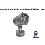
Performance floodlight with minimal diffuse light percentage

Instructions for use
Application
Performance floodlight with G½ mounting bush.
The floodlight can be bolted together with any female thread G½ according to ISO 228 supplied by others or to BEGA accessories. For a variety of interior and exterior lighting applications.
BEGA Ultra dark Optics® offer a maximum of illumination and eye comfort due to a minimised diffuse light percentage and highly efficient glare suppression.
Product description
Luminaire made of aluminium alloy, aluminium and stainless steel BEGA Uni dure ® coating technology Colour graphite or silver Matt safety glass Internal louvres and polymer lens BEGA Ultra dark Optics® Louvres and interior surface of anti-glare ring with maximum light-absorbing ultra-black nano-coating Rotation range of floodlight 350° Swivel range -30°/+100° Mounting bracket with G½ threaded connection.
Thread length: 14mm
Connecting cable X05BQ-F 5G1mm² Cable length 1m BEGA Ultimate Driver® Complies with flicker requirements in accordance with IEEE 1789, DIN IEC/TR 63158, DIN IEC/TR 61547-1 LED power supply unit 220-240 V ![]() 0/50-60 Hz DC 176-264 V DALI-controllable
0/50-60 Hz DC 176-264 V DALI-controllable
Number of DALI addresses: 1
Basic insulation is provided between the mains and control cables BEGA Thermal Control® Temporary thermal regulation to protect temperature-sensitive components without switching off the luminaire Safety class I Protection class IP 65 Dust-tight and protection against water jets.
![]() Conformity mark
Conformity mark
Wind catching area: 0.021 m² This product contains light sources of energy efficiency class(es) E, F
Lighting technology
Symmetrically focused broad spread light distribution with minimal diffuse light percentage.
Half beam angle 56°
Safety
The installation and operation of this luminaire are subject to national safety regulations. Installation and commissioning may only be carried out by a qualified electrician. The manufacturer accepts no liability for damage caused by improper use or installation. If subsequent modifications are made to the luminaire, the person responsible for these modifications shall be considered the manufacturer.
Overvoltage protection
The electronic components installed in the luminaire are protected against overvoltage in accordance with DIN EN 61547.
To achieve an additional protection against e.g. transients, etc. we recommend separate overvoltage protection components. You can find them on our website at www.bega.com.
The ideal protection of all electronic components installed in the luminaires is achieved by using bounce-free switching contacts such as an electronic relay (solid-state relay), e.g. BEGA 71320.
Please note:
Contact with the inner surface of the luminaire reflector should be avoided in order to permanently protect the special stray light minimizing properties of the nano-coating.
Installation
Screw the floodlight G½ threaded connection firmly into the on-site G½ female thread or BEGA accessory.
G½ threaded connection torque = 40Nm.
Secure the screw connection from loosening on site (if provided with locking screw S, see fig. A).

Check the earth conductor connection between the G½ threaded connection and the on-site G½ female thread.
Adjust floodlight:
Undo hexagon socket screw (wrench size 5 mm) and hexagon nut (wrench size 27 mm) and set the desired beam direction (see sketch B,C).


Torque:
Hexagon socket screw = 7 Nm
Hexagon nut = 35 Nm
Secure bolted connection G 1/2 against loosening by tightening the hexagon socket screws (wrench size 2 mm).
The electrical connection must be carried out with matching protection class and safety class, strain-relieved, with suitable connection terminals (not included in the scope of delivery) at the luminaire power supply cable.
Note correct configuration of the mains supply cable. The earth conductor is connected at the green-yellow (1), the phase to the brown (L), and the neutral conductor to the blue (N) marked wire.
The connection of the control cables is achieved by means of the both leads marked with DALI. In case these leads are not used the luminaire will be operated at full light output.
Lamp
| Module connected wattage | 18.3 W |
| Luminaire connected wattage | 20.5 W |
| Rated temperature | ta=25 °C |
| Service life criteria | 50000 h/L70 |
85 239K3
| Module designation | LED-1254/930 |
| Color temperature | 3000 K |
| Color rendering index | CRI >90 |
| Module luminous flux | 2190 lm |
| Luminaire luminous flux | 1098 lm |
| Luminaire luminous efficiency | 53,6 lm/W |
85 239K4
| Module designation | LED-1254/940 |
| Color temperature | 4000 K |
| Color rendering index | CRI >90 |
| Module luminous flux | 2375 lm |
| Luminaire luminous flux | 1190 lm |
| Luminaire luminous efficiency | 58 lm/W |
Cleaning · Maintenance
Clean luminaire regularly with solvent-free cleansers from dirt and deposits. Do not use high pressure cleaners.
Maintenance
The connecting cable must be checked for external damage and may only be replaced by a qualified electrician.
Please note:
Do not remove the desiccant bag from the luminaire housing.
It is needed to remove residual moisture.
Replacing the LED module
The designation of the LED module is noted on a separate label in the luminaire or on the underside of the specific LED module. The light colour and light output of BEGA replacement modules correspond to those of the modules originally fitted. The module can be replaced by a qualified person using commercially available tools.
Disconnect the system from the power supply. Open the floodlight:
Loosen the locking pin (hexagon socket wrench SW2.5) on the back of the floodlight housing. Remove the trim ring along with the safety glass and reflector by twisting it anti-clockwise.
Please note:
Contact with the inner surfaces of the louvres and luminaire reflector should be avoided in order to permanently protect the special stray light-minimizing properties of the nano-coating.
Grasp the louvres from the outside and lift them out. Loosen the three mounting screws (Torx drive T20) and lift the lens holder (with the loosely inserted lenses) upward horizontally out of the housing.
Replace LED module.
Please follow the installation instructions for the LED module.
Install in reverse order.
When installing the lens holder, make sure that the LED connecting cable is not pinched.
Inspect and, if necessary, replace the luminaire gaskets.
Defective glass must be replaced.
Place the trim ring with glass and reflector on the floodlight housing so that the notches in the trim ring and luminaire housing sit on top of each other.
Twist on the trim ring clockwise as far as the stop. Screw in the locking pin.
Accessories
| 71332 | Shield |
| 71 338 | Cylindrical shield |
| 70 214 | Pole cap for pole ø 48 mm |
| 70 248 | Pole cap for pole ø 60 mm |
| 70 245 | Mounting box |
| 70 252 | General fastener |
| 70 280 | Tube clamp G½ |
| 70 283 | Screw clamp |
| 70 379 | Cross beam G½ |
| 70 889 | Tension belt |
For the accessories a separate instructions for use can be provided upon request.
Spares
| Spare glass internal | 14 001 631 |
| Trim ring graphite with glass | 25 000 277 |
| Trim ring silver with glass | 25 000 278 |
| LED power supply unit | DEV-0485/900i |
| LED module 3000 K | LED-1254/930 |
| LED module 4000 K | LED-1254/940 |
| Gasket housing | 83 000 521 |
| Gasket trim ring | 83 001 952 |
Customer Support
BEGA Gantenbrink-Leuchten KG · Postfach 3160 · 58689 Menden
info@bega.com
www.bega.com

Documents / Resources
 |
BEGA 85 239 Performance Floodlight with Minimal Diffuse Light [pdf] Instruction Manual 85239K3, 85239K4, 85 239, 85 239 Performance Floodlight with Minimal Diffuse Light, Performance Floodlight with Minimal Diffuse Light, Floodlight with Minimal Diffuse Light, Minimal Diffuse Light, Diffuse Light, Light |