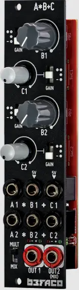
befaco C_V4 Two Module Channels
THANKS FOR PURCHASING A MODULE FROM BEFACO!
Instructions
BEFORE YOU PLUG THIS MODULE IN .
- Disconnect your cabinet from the mains.
- Triple-check the power cord polarity. The colored line on the cable (pin number one) is the -12V rail.
- If you plug the module backward you might burn it out and unfortunately, this is not covered by the warranty.
- If you have any questions about this product feel free to contact us support@befaco.org

WHAT IS A*B+C?
- A*B+C is the ultimate utility for audio and control voltage.
- It performs multiplication, addition, and attenuation, providing a simple way to create complex signal interactions and timbres.
- It is formed by two channels, each of which takes two input signals (A and B), multiplies them (Ax B), and then adds a third signal (C) to the result.
- The two channels can be MULTor MIX acting as a signal splitter or a two-channel mixer.
By combining different blocks, many functions can be achieved:
- Four-quadrant amplitude modulation (ring mod.)
- Linear VCA
- Signal mixer
- 2x gain amplifier
- Phase inverter
- Attenuator
- 2 channel Multi
- Voltage-controlled attenuator
- CV mixer
- Attenuator
- Inverter
- VCA
- DC generator
Core Function
The two module channels perform the same mathematical operation: (AX B) + C
Where
- A, B, and Care inputs that can accept signals (control voltages or audio).
- B and Care normally to 5V, automatically providing a default voltage if nothing is plugged in.
- Depending on the Gain switch, the level of B can be kept the same, inverted, or doubled
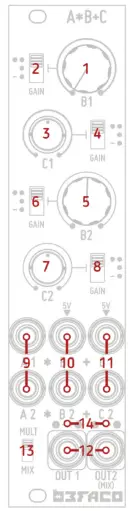
CONTROLS
- Manual Attenuator of 8 IN of channel 1
Adjusting this control changes the amplitude of the signal at IN B1. At the leftmost setting, the amplitude is zero. As you move to the right, the level increases based on the B1 Gain Switch (2) - 81 Gain Switch
This switch scales the signal at B 1 by either 1 (· ), 2( •• ), or -1 (-•) - Manual Attenuator of C IN of channel 1
Adjusting this control changes the amplitude of the signal at IN C2. At the leftmost setting, the amplitude is zero. As you move to the right, the level increases based on the C2 Gain Switch (8) - C1 Gain Switch
This switch scales the signal at C1 by either 1 (·), 2(··), or-1 (-·) - Manual Attenuator of 8 IN of channel 2
Adjusting this control changes the amplitude of the signal at IN B2. At the leftmost setting, the amplitude is zero. As you move to the right, the level increases based on the B2 Gain Switch (6). - 82 Gain Switch
This switch scales the signal at B2 by either 1 (· ), 2( •• ), or -1 (-·) - Manual Attenuator of C IN of channel 2
Adjusting this control changes the amplitude of the signal at IN C2. At the leftmost setting, the amplitude is zero. As you move to the right, the level increases based on the C2 Gain Switch (8). - C2 Gain Switch
This switch scales the signal at C2 by either 1 ( • ), 2(·· ), or -1 (-·) - A 1 and A2 Inputs
A Input jacks for channels 1 and 2 respectively - B1 and B2 Inputs
B Input jacks for channels 1 and 2 respectively - C1 and C2 Inputs
C Input jacks for channels 1 and 2 respectively - OUTs 1 and 2
Output jacks for channels 1 and 2, respectively. Out 2 functions as a mixed output of channels 1 and 2 if the MIX mode is selected via the Mode Switch (13). - Mode Switch
Selector for Splitter or Mixer modes or combining the two channels - Level LEDs
Level Indicator for the Outputs. Green indicates positive voltage and red indicates negative.
Internal structure
Multiplication (Ax B):
The signal A is multiplied by the signal at B. As a result, the level of B directly affects the A level by multiplying their voltages at any given moment
As it is a multiplication the general rules of multiplication apply
- If B=O Volt or A=O Volt, A*B will always be = 0 volt
- If A or Bare negative voltages A*B will always have negative sing
- If A and Bare negative voltages A*B will always have positive sing
- A*B=B*A The order of the factors doesn’t change the result.
Level adjustment
To ensure that voltage levels remain appropriate for modular synthesizers, the voltage resulting from multiplication (A * B) is always divided internally by a factor of 5. Without this adjustment, the output voltage could easily exceed acceptable limits due to the nature of the multiplication operation.
As a result, when 5 volts are applied to either input A or B, the output will produce a unity gain, meaning it will equal the other input This can be understood by applying the identity property of multiplication, which states that
If you multiply any number by 1, the result is the number itself: X * 1 = X.
On top of that, the gain switch, scales the B signal by either 1, 2, or -1:
- Setting 1 (•): gain ranges from Oto 1 (attenuator).
- Setting 2(••): gain ranges from Oto 2 (doubling amplifier)
- Setting -1 (-•): gain ranges from Oto -10 (inverting attenuator)
B is normalized to 5 volts and A is multiplied by B, so if a signal is plugged into A and the B jack remains unpatched, the B pot becomes a manual level control for A
Addition ( +C)
The result of Ax B is added to the signal at jack C.
Just like at point B, if nothing is connected to point C, the voltage defaults to 5 volts. This introduces an offset to the output The voltage of this output depends on the gain switch setting, which scales the signal at point C by factors of either 1, 2, or -1 .
- Setting 1 (•): gain ranges from Oto 1 (attenuator).
- Setting 2(••): gain ranges from Oto 2 (doubling amplifier)
- Setting -1 (-•): gain ranges from Oto -10 (inverting attenuator)
Channels Combination
- Each of the two channels can be combined in two ways, depending on the setting of the Mode switch:
- MULT: This mode sends the signal present at A on channel 1 to A on channel B, effectively splitting the same signal to both channels and functioning as a Mult. This is achieved by normalizing A 1 to A2; once a jack is connected to A2, the normalization is broken, and the channels become independent.
- MIX: In this mode, the outputs of the two channels are blended, functioning as a mixer. This is accomplished by normalizing OUTl to the mix bus; when a jack is connected to OUT2, the normalization is broken, and the channels become independent.
Operational Levels
- All inputs accept voltages in the range of+/- 10 volts.
- Any voltage exceeding 10 volts will be clipped internally, whether it originates from external signals or results from internal operations. This feature is useful for maintaining signal levels suitable for modular synthesizers or for adding distortion to audio signals.
- Each channel is equipped with two LEDs located above the outputs. These LEDs indicate the output levels for each channel: a green LED signifies positive voltage, while a red LED indicates negative voltage.
A*B+C Diagram

SPECS AND CREDITS
- Current needs: + 12V: 50mA, -12: 50mA, 5v:0
- Width: 6 HP
- Depth: Assembled version 25 mm
- Depth: 25 mm Assembled version – 35 mm DIV version
Designed with care and love by the Befaco Team in Barcelona – 2025
Documents / Resources
 |
befaco C_V4 Two Module Channels [pdf] User Manual C_V4 Two Module Channels, C_V4, Two Module Channels, Module Channels |


