Autonics ASS-HC16MP0-NN SSR Terminal Block

Important Information
For your safety, read and follow the considerations written in the instruction manual, other manuals and Autonics website.
The specifications, dimensions, etc. are subject to change without notice for product improvement. Some models may be discontinued without notice.
Features
- Screw type connection for stable and reliable connection
- Contactless relay ideal for systems requiring long life-cycle and high-speed response
- Compact, space-saving design
- Comprehensive connection type for use without jumper bar
- Operation status indicator (blue LED)
- DIN rail mount and screw mount installation
- Convenient SSR removal with ejector clip
- SSR protection cover
※ Autonics CH/CO series I/O terminal block cables are recommended for best performance.
Safety Considerations
- Observe all ‘Safety Considerations’ for safe and proper operation to avoid hazards.
 symbol indicates caution due to special circumstances in which hazards may occur.
![]() Warning Failure to follow instructions may result in serious injury or death.
Warning Failure to follow instructions may result in serious injury or death.
- Fail-safe device must be installed when using the unit with machinery that may cause serious injury or substantial economic loss.(e.g. nuclear power control, medical equipment, ships, vehicles, railways, aircraft, combustion apparatus, safety equipment, crime/disaster prevention devices, etc.)
Failure to follow this instruction may result in personal injury, economic loss or fire. - Do not use the unit in the place where flammable/explosive/corrosive gas, high humidity, direct sunlight, radiant heat, vibration, impact or salinity may be present.
Failure to follow this instruction may result in explosion or fire. - Do not connect, repair, or inspect the unit, remove connector, or change SSR while connected to a power source.
Failure to follow this instruction may result in fire or electric shock. - Do not disassemble or modify the unit.
Failure to follow this instruction may result in fire or electric shock.
![]() Caution Failure to follow instructions may result in injury or product damage.
Caution Failure to follow instructions may result in injury or product damage.
- Use the unit within the rated specifications.
Failure to follow this instruction may result in fire or product damage. - Use a dry cloth to clean the unit, and do not use water or organic solvent.
Failure to follow this instruction may result in fire or electric shock. - Keep the product away from metal chip, dust, and wire residue which flow into the unit.
Failure to follow this instruction may result in fire or product damage. - Do not use the product when a screw of terminal is loosened.
Failure to follow this instruction may result in fire or product damage.
Cautions during Use
- Follow instructions in ‘Cautions during Use’. Otherwise, it may cause unexpected accidents.
- Check the polarity of power or COMMON before connecting PLC or other controllers.
- Do not touch the unit immediately after the load power is supplied or cut.
It may cause burn by high temperature. - 24VDC
 power supply should be insulated and limited voltage/current or Class 2, SELV power supply device.
 - Wire as short as possible and keep away from high voltage lines or power lines, to prevent surge and inductive noise. Do not use near the equipment which generates strong magnetic force or high frequency noise (transceiver, etc.). In case installing the product near the equipment which generates strong surge (motor, welding machine, etc.), use diode or varistor to remove surge.
- This unit may be used in the following environments.
- Indoors (in the environment condition rated in ‘Specifications’)
- Altitude max. 2,000 m
- Pollution degree 2
- Installation category II
Product Components
- Product
- Instruction manual
- Ejector
Sold Separately
- I/O cable CH/CO Series
Ordering Information
This is only for reference, the actual product does not support all combinations.
For selecting the specified model, follow the Autonics website.
- Connector type
H: Hirose connector - Wire connection
C: Common - The number of SSR
16: 16-point
32: 32-point - SSR type
MP0: AQZ202D [Panasonic] - Input logic
N: NPN (+COM)
P: PNP (-COM) - Varistor
N: None

Specifications
| Model | ASS-HC16MP0-□N | ASS-HC32MP0-□N |
| Applied SSR 01) | AQZ202D [Panasonic] | |
| Output method | 1a | 1a |
| Power supply | ≤ 24 VDC |
≤ 24 VDC |
| Current consumption | ≤ 10.4 mA 02) or ≤ 13.1 mA 03) | ≤ 11.5 mA 02) or ≤ 15.3 mA 03) |
| SSR output rated spec. | 24 VAC∼50/60 Hz 1.6A, 24 VDC (1.6 A / 1-point, 8 A / 1COM) |
24 VAC∼50/60 Hz 1.6A, 24 VDC (1.6 A / 1-point, 8 A / 1COM) |
| No. of connector pins | 20 | 40 |
| Connector for controller side | 20-pin Omron (XG4A-2031) | 40-pin Hirose
(HIF3BA-40PA-2.54DSA) |
| No. of SSR points | 16 | 32 |
| Output connection | 8-point/1COM | 8-point/1COM |
| Terminal type | Screw | Screw |
| Terminal pitch | 7.62 mm | 7.62 mm |
| Indicator | Power indicator: red, operating indicator: blue | Power indicator: red, operating indicator: blue |
| Varistor | None | None |
| Input logic | NPN / PNP model | NPN / PNP model |
| Material | CASE, BASE, COVER: PC,
terminal pin: brass, Ni-plating |
CASE: MPPO, BASE: PA66 (G25%),
COVER: PC, terminal pin: brass, Ni-plating |
| Approval |  |
|
| Unit weight (packaged) | ≈ 185 g (≈ 232 g) | ≈ 370 g (≈ 463 g) |
- For the detailed information about the SSR, please refer to ‘SSR’ or data sheet from the manufacturer.
- It is current consumption per a SSR including LED current.
- It is current consumption including LED current for power part to 02).
| Insulation resistance | ≥ 1,000 MΩ (500 VDC |
| Dielectric strength (coil-contact) | 2,500 VAC∼50/60 Hz for 1 minute |
| Dielectric strength (same polarity contact) | 1,000 VAC∼ 50/60 Hz for 1 minute |
| Vibration | 0.75mm amplitude at frequency of 10 to 55Hz in each X, Y, Z direction for 2 hours |
| Vibration (malfunction) | 0.75mm amplitude at frequency of 10 to 55Hz in each X, Y, Z direction for 10 min |
| Shock | 300 m/s² (≈ 30 G) in each X, Y, Z direction for 3 times |
| Shock (malfunction) | 150 m/s² (≈ 15 G) in each X, Y, Z direction for 3 times |
| Ambient temperature | -15 to 55 ℃, storage: -25 to 65 ℃ (no freezing or condensation) |
| Ambient humidity | 35 to 85 %RH, storage: 35 to 85 %RH (no freezing or condensation) |
| Applicable wire – solid | Ø 0.3 to Ø 1.2 mm |
| Applicable wire – stranded | AWG 22-16 (0.30 to 1.25 mm²) |
| Tightening torque | 0.5 to 0.6 N·m |
Crimp Terminal Specifications
- Unit: mm, Use the UL approved crimp terminal.

Replacing SSR
- Disassemble a SSR by using Two Way Ejector for SSR replacement inside the product.

- After checking the location of the SSR socket, insert the SSR to be replaced.

Dimensions
- Unit: mm, For the detailed drawings, follow the Autonics website.

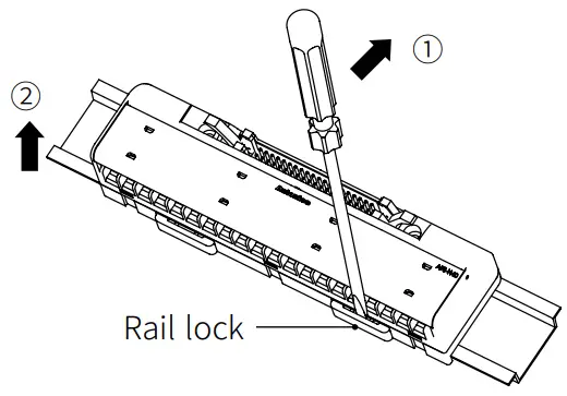
Installation
DIN Rail
- Mounting
- Pull the Rail lock on the rear of the product to the direction ①.
- Hang DIN rail hook on the rear of the product onto DIN rail.
- Push the product to the direction ②, and push the Rail lock to the direction ③ to fix onto the DIN rail.

- Removing
- Insert a tool such as screwdriver into the hole of Rail lock.
- Push the tool to the direction ① and pull the Rail lock.
- Lift bottom of the product to the direction ② and remove the product from DIN rail.
Panel
Product with the mounting hole can be installed on panel with screw.
It is recommended to use M4×15 mm of spring washer screws.
If you use flat washer, its diameter should be Ø 6 mm.
Tighten the screw with the tightening torque of 0.7 to 1.0 N·m.
Example
- When two or more terminal blocks are installed
: Use a stopper (sold separately) to make space between devices.

Temperature Characteristic Graph
- Load current by ambient temperature for each rated current

VIN: 24 VDC - VIN is input voltage
Wire Connection
Wire connection
- 16-point NPN

- 16-point PNP

A Pin 20 18 16 14 12 10 8 6 19 17 15 13 11 9 7 5 COM COM COM1 COM2 B Upper terminal – 01 – 03 – 05 – 07 08 – 0A – 0C – 0E – – R2 – R4 – R6 – R8 R9 – R11 – R13 – R15 – C Low terminal 00 – 02 – 04 – 06 – – 09 – 0B – 0D – 0F R1 – R3 – R5 – R7 – – R10 – R12 – R14 – R16 - 32-point NPN

- 32-point PNP

A Pin 40 38 36 34 32 30 28 26 24 22 20 18 16 14 12 10 COM COM COM1 COM2 B Upper terminal – 01 – 03 – 05 – 07 08 – 0A – 0C – 0E – – R2 – R4 – R6 – R8 R9 – R11 – R13 – R15 – C Low terminal 00 – 02 – 04 – 06 – – 09 – 0B – 0D – 0F R1 – R3 – R5 – R7 – – R10 – R12 – R14 – R16 A Pin 39 37 35 33 31 29 27 25 23 21 19 17 15 13 11 9 COM COM COM3 COM4 B Upper terminal – 11 – 13 – 15 – 17 18 – 1A – 1C – 1E – – R18 – R20 – R22 – R24 R25 – R27 – R29 – R31 – C Low terminal 10 – 12 – 14 – 16 – – 19 – 1B – 1D – 1F R17 – R19 – R21 – R23 – – R26 – R28 – R30 – R32
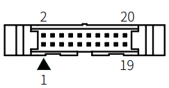
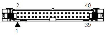
Hirose connector pin arrangement
- 20-pin connector
Omron (XG4A-2031)
- 40-pin connector
Hirose (HIF3BA-40PA-2.54DSA)
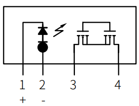
SSR AQZ202D [Panasonic]
Input
| Rated voltage | Operate voltage | Release voltage | Input impedance |
| 30 VDC |
≥ 4 V | ≤ 1.3 V | – |
Output
| Manufacture | Panasonic |
| Contact
arrangement |
SPST-1a (N.O) |
| Load voltage range | 60 VAC∼ / DC |
| Max. load current | ≤ 2.7 A |
| Min. load current | – |
| Non-repetitive surge
current |
9 A (Peak) |
| Output OFF leakage
current |
10 μA |
| Output ON on voltage | – |
| Insulation resistance | ≥ 1,000 MΩ (500 VDC |
| Dielectric strength (contact-coil) | 2,500 VAC∼ 50/60 Hz for 1 minute |
| Operate time | ≤ 10 ms |
| Release time | ≤ 3 ms |
| Ambient temperature | -40 to 60 ℃, storage: -40 to 100 ℃ (a non freezing or condensation environment) |
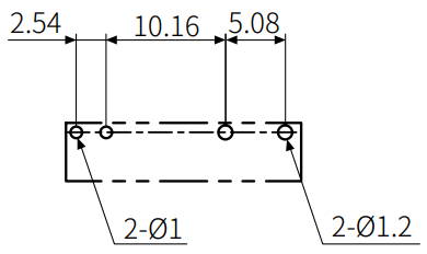
Dimensions
- unit: mm

- Circuit diagram (bottom view)
- PCB pattern
It was written based on the data provided by each manufacturer, but there is room for change, so be sure to check the manufacturer’s data.
CUSTOMER SUPPORT
18, Bansong-ro 513Beon-gil, Haeundae-gu, Busan, Republic of Korea, 48002
www.autonics.com | +82-2-2048-1577 | sales@autonics.com
Documents / Resources
 |
Autonics ASS-HC16MP0-NN SSR Terminal Block [pdf] User Manual ASS-HC16MP0-NN SSR Terminal Block, ASS-HC16MP0-NN, SSR Terminal Block, Terminal Block, Block |


