AMP SECURE AFL-4037 120V Twin Wall Flood Light Installation Guide
![]()

AMP® SECURE Twin Wall Flood Light, 120V
ITEM: AFL-4037-30S-LI-S & AFL-4038-30S-MS-LI-S
INSTALLATION & MAINTENANCE GUIDE
AMP® SECURE Twin Wall Flood Light
AFL-4037-30S-LI-S & AFL-4038-30S-MS-LI-S
![]() IMPORTANT: PLEASE READ BEFORE INSTALLATION
IMPORTANT: PLEASE READ BEFORE INSTALLATION
READ CAREFULLY BEFORE INSTALLING FIXTURE. RETAIN THESE INSTRUCTIONS FOR FUTURE REFERENCE.
Fixtures must be wired in accordance with all local codes and the National Electrical Code.
Proper grounding is required for safety.
THIS PRODUCT MUST BE INSTALLED IN ACCORDANCE WITH THE APPLICABLE INSTALLATION CODE BY A PERSON FAMILIAR WITH THE CONSTRUCTION AND OPERATION OF THE PRODUCT AND THE HAZARDS INVOLVED.
WARNING: Make certain power is OFF before installing or maintaining fixture. No user-serviceable parts inside.
Suitable for Wet locations.
Installation or Assembly Instructions.
![]() IMPORTANT SAFETY INSTRUCTIONS
IMPORTANT SAFETY INSTRUCTIONS
- This LED area light uses the latest in solid state lighting technology for long life, low maintenance, and high efficiency.
- An internal power-factor-corrected switch-mode supply allows it to be used from any nominal 120VAC driver without any variation in light output.
- Suitable for use in the following locations:
- Ambient Temp: -40~+40°C (-40~+104°F)
- Wet Locations
- Be sure the supply voltage is suitable for the Luminaire voltage.
PACKAGE CONTENTS
A. (1) Luminaire
B. (2) Outlet Box Screws
C. (3) P4 Connectors
D. (2) P2 Connectors
E. (1) Clear Cap
PRODUCT DIMENSIONS

1 REMOVE MOUNTING PLATE

Loosen the mounting screws until the mounting plate disengages.
2 MOUNTING PLATE INSTALLATION

Secure the mounting plate to the junction box using the screws supplied or the screws that come with the junction box. Use the bubble level to level the mounting plate.
3 TETHER
Secure the Tether Ball into the Mounting Plate Notch to help with hands-free wiring.
4 CONNECT THE LUMINAIRE WIRES TO THE SUPPLY WIRES

Feed the Supply Wires through the Mounting Plate.
Make the connections as follows:
Connect the Green Ground wire to the Green luminaire wire;
Connect the White wire to the White luminaire wire;
Connect the Black wire to the Black luminaire wire;
Connect the dimming wires if present – Purple wire to Purple wire and Pink Wire to Pink wire. Compatible with 0-10V dimmers.
If dimming wires are not present, cap them with the smaller P2 wire connectors.
5 INSTALL LUMINAIRE

- Carefully insert all the wires and connections into the Junction Box.
- Place the fixture Coverplate over the Mounting Plate.
- Secure with (2) Mounting Screws.
- Tighten.
6 APPLY WEATHERPROOF SILICONE SEALANT

IMPORTANT NOTE:
Apply Weatherproof Silicone Sealant around the edge of the Coverplate. Do NOT apply the sealant to the bottom of the wallplate. Leave a space at the bottom of the wallplate for potential drainage.
7 ACCESS TO SELECTION SWITCHES

Remove threaded plug from the left and right sides of the coverplate to access the selection switches.
8 COLOR TEMPERATURE (CCT) & POWER SELECT SWITCHES

9 COVER TO SELECTION SWITCHES

Reinstall the threaded plugs with o-ring on the left and right sides of the coverplate.
10 PHOTOCELL FUNCTION

To use the built-in Photocell function: Remove the Black Cap and replace it with the Clear Cap.
11 ADJUST MOTION SENSOR

The detection angle of the Motion Sensor is 120°.
To adjust, loosen the Thumb Screw and aim.
Tighten the Thumb Screw.
12 LIGHT CONTROL SWITCH AND TIME SETTING SWITCH
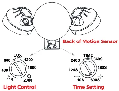
There are two rotary switches on the back of the Sensor.
Adjust the light control switch to adjust at which light level the sensor will begin to operate. Estimated lux level at sunset is 400 lux for light control rotary switch.
Adjust the time setting switch to set the time the lights will stay on after motion ceases.
13 ADJUST LUMINAIRE DIRECTIONS

Loosen the Thumb Screw and adjust the angle of the Luminaire. Tighten the Thumb Screw.

![]()
1-813-978-3700 • Mon-Fri 9am-6pm (ET)
Specifications and product details subject to change without notice.
© Copyright 2024, AMP® Lighting, Lutz FL USA 33549 • All rights reserved.
customersupport@amplighting.com • amplighting.com
Documents / Resources
 |
AMP AFL-4037 SECURE Twin Wall Flood Light [pdf] Installation Guide AFL-4037 SECURE Twin Wall Flood Light, AFL-4037, SECURE Twin Wall Flood Light, Twin Wall Flood Light, Flood Light, Light |