LAUNCHKEY MK4 MIDI Keyboard Controllers

Specifications:
- Product: Launchkey MK4
- Version: 1.0
- MIDI Interfaces: USB and MIDI DIN output port
Product Information
The Launchkey MK4 is a MIDI controller that communicates using MIDI over USB and DIN. It features two MIDI interfaces, providing two pairs of MIDI inputs and outputs over USB. Additionally, it has a MIDI DIN output port that transmits the same data as received on the host port MIDI In (USB).
Bootloader:
The device has a bootloader for initializing the system.
MIDI on Launchkey MK4:
If you wish to use the Launchkey as a control surface for a DAW (Digital Audio Workstation), you can switch to DAW mode. Otherwise, you can interact with the device using the MIDI interface.
SysEx Message Format:
The SysEx messages used by the device have specific header formats based on the SKU type, followed by command bytes for selecting functions and data required for those functions.
Standalone (MIDI) Mode:
The Launchkey powers up into Standalone mode, which does not provide specific functionality for DAW interaction. However, it sends MIDI Control Change events on Channel 16 for capturing events on the DAW control buttons.
Product Usage Instructions
- Power Up: The Launchkey MK4 powers up into Standalone mode.
- Switching Modes: To use DAW mode, refer to the DAW interface. Otherwise, interact with the device using the MIDI interface.
- SysEx Messages: Understand the SysEx message format used by the device to communicate effectively.
- MIDI Control: Utilize MIDI Control Change events on Channel 16 for capturing events on the DAW control buttons.
FAQ:
Q: How do I switch between Standalone mode and DAW mode on Launchkey MK4?
A: To switch to DAW mode, refer to the DAW interface. Otherwise, the device powers up into Standalone mode by default.
PROGRAMMER’S
Reference GUIDE
Version 1.0
Launchkey MK4 Programmer’s Reference Guide
About this Guide
This document provides all the information you need to be able to control the Launchkey MK4. The Launchkey communicates using MIDI over USB and DIN. This document describes the MIDI implementation for the device, the MIDI events coming from it, and how the Launchkey’s various features can be accessed through MIDI messages.
MIDI data is expressed in this manual in several ways:
- A plain English description of the message.
- When we describe a musical note, middle C is deemed to be ‘C3’ or note 60. MIDI channel 1 is the lowest-numbered MIDI channel: channels range from 1 to 16.
- MIDI messages are also expressed in plain data, with decimal and hexadecimal equivalents. The hexadecimal number will always be followed by an ‘h’ and the decimal equivalent given in brackets. For example, a note on message on channel 1 is signified by the status byte 90h (144).
Bootloader
The Launchkey has a bootloader mode that allows the user to view the current FW versions, and enable/disable Easy Start. The bootloader is accessed by holding the Octave Up and Octave Down buttons together whilst powering up the device. The screen will display the current Application and Bootloader version numbers.
The Record button can be used to toggle Easy Start. When Easy Start is ON, the Launchkey shows up as a Mass Storage Device to provide a more convenient first-time experience. You can turn this off once you are familiar with the device to disable this Mass Storage Device.
The Play button can be used to start the Application.
MIDI on Launchkey MK4
The Launchkey has two MIDI interfaces, providing two pairs of MIDI inputs and outputs over USB. They are as follows:
- MIDI In / Out (or first interface on Windows): This interface is used to receive MIDI from performing (keys, wheels, pad, pot, and fader Custom Modes); and is used to provide external MIDI input.
• DAW In / Out (or second interface on Windows): This interface is used by DAWs and similar software to interact with the Launchkey.
The Launchkey also has a MIDI DIN output port, which transmits the same data a as is received on host port MIDI In (USB). Note that this excludes responses to requests issued by the host to the Launchkey on MIDI Out (USB).
If you wish to use Launchkey as a control surface for a DAW (Digital Audio Workstation), you will likely want to use the DAW interface (See DAW Mode [11]).
Otherwise, you may interact with the device using the MIDI interface. The Launchkey sends Note On (90h – 9Fh) with velocity zero for Note Offs. It accepts either Note Offs (80h – 8Fh) or Note Ons (90h – 9Fh) with velocity zero for Note Off.
SysEx message format used by the device
All SysEx messages begin with the following header, regardless of direction (Host → Launchkey or Launchkey → Host):
Regular SKUs:
- Hex: F0h 00h 20h 29h 02h 14h
- Dec: 240 0 32 41 2 20
Mini SKUs:
- Hex: F0h 00h 20h 29h 02h 13h
- Dec: 240 0 32 41 2 19
After the header is a command byte, selecting the function to use, and then whatever data is required for that function.
Standalone (MIDI) mode
The Launchkey powers up into Standalone mode. This mode does not provide specific functionality for interaction with DAWs, the DAW in/out (USB) interface remains unused for this purpose. However, to provide means for capturing events on the Launchkey’s DAW control buttons, they do send MIDI Control Change events on Channel 16 (MIDI status: BFh, 191) on the MIDI in / out (USB) interface and the MIDI DIN port:

Figure 2. Hexadecimal:
The Start and Stop buttons (Start and Shift + Start on Launchkey Mini SKUs) output the MIDI Real Time Start and Stop messages respectively
When creating Custom Modes for the Launchkey, keep these in mind if you are setting up controls to operate on MIDI Channel 16.
DAW mode
DAW mode provides DAWs and DAW-like software functionality to realise intuitive user interfaces on the Launchkey’s surface. The capabilities described in this chapter are only available once DAW mode is enabled.
All functionality described in this chapter is accessible through the DAW In/Out (USB) interface.
DAW mode control
Enable DAW Mode:
- Hex: 9fh 0Ch 7Fh
- Dec: 159 12 127
Disable DAW Mode:
- Hex: 9Fh 0Ch 00h
- Dec: 159 12 0
When the DAW or DAW-like software recognises the Launchkey and connects to it, it should first enter DAW mode (send 9Fh 0Ch 7Fh), and then, if necessary, enable the feature controls (see the “Launchkey MK4 feature controls” section of this document) When the DAW or DAW-like software exits, it should exit from DAW mode on the Launchkey (send 9Fh 0Ch 00h) to return it to Standalone (MIDI) mode.
The surface in DAW mode
In DAW mode, contrary to standalone (MIDI) mode, all buttons, and surface elements not belonging to performance features (such as the Custom Modes) can be accessed and will report on the DAW In/Out (USB) interface only. The buttons except for those belonging to the Faders are mapped to Control Change events as follows:
Figure 3. Decimal: Figure 4. Hexadecimal:
 The Control Change indices listed are also used for sending colour to the corresponding LEDs (if the button has any), see Colouring the surface [14].
Additional modes available in DAW mode
Once in DAW mode, the following additional modes become available:
- DAW mode on the pads.
- Plugin, Mixers, Sends & Transport on the encoders.
- Volume on the faders (Launchkey 49/61 only).
When entering DAW mode, the surface is set up in the following manner:
- Pads: DAW.
- Encoders: Plugin.
- Faders: Volume (Launchkey 49/61 only).
The DAW should initialise each of these areas accordingly.
Mode report and select
The modes of the pads, encoders, and faders can be controlled by MIDI events and are reported back by the Launchkey whenever it changes mode due to user activity. These messages are important to capture, as the DAW should follow them when setting up and using the surfaces as intended based on the selected mode.
Pad modes
Pad mode changes are reported or can be changed by the following MIDI event:
- Channel 7 (MIDI status: B6h, 182), Control Change 1Dh (29)
The Pad modes are mapped to the following values:
- 01h (1): Drum layout
- 02h (2): DAW layout
- 04h (4): User Chords
- 05h (5): Custom Mode 1
- 06h (6): Custom Mode 2
- 07h (7): Custom Mode 3
- 08h (8): Custom Mode 4
- 0Dh (13): Arp Pattern
- 0Eh (14): Chord Map
Encoder modes
Encoder mode changes are reported or can be changed by the following MIDI event:
- Channel 7 (MIDI status: B6h, 182), Control Change 1Eh (30)
The encoder modes are mapped to the following values:
- 01h (1): Mixer
- 02h (2): Plugin
- 04h (4): Sends
- 05h (5): Transport
- 06h (6): Custom Mode 1
- 07h (7): Custom Mode 2
- 08h (8): Custom Mode 3
- 09h (9): Custom Mode 4
Fader modes (Launchkey 49/61 only)
Fader mode changes are reported or can be changed by the following MIDI event:
- Channel 7 (MIDI status: B6h, 182), Control Change 1Fh (31)
The fader modes are mapped to the following values:
- 01h (1): Volume
- 06h (6): Custom Mode 1
- 07h (7): Custom Mode 2
- 08h (8): Custom Mode 3
- 09h (9): Custom Mode 4
DAW mode
The DAW mode on pads is selected on entering DAW mode, and when the user selects it by the Shift menu. The pads report back as note (MIDI status: 90h, 144) and aftertouch (MIDI status: A0h, 160) events (the latter only if Polyphonic Aftertouch is selected) on Channel 1, and can be accessed for colouring their LEDs by the following indices:

Drum mode
The Drum mode on pads can replace the Drum mode of standalone (MIDI) mode, providing a capability to the DAW to control its colours and receive the messages on the DAW MIDI port. This is done by sending the below message:
- Hex : B6h 54h Olh
- Dec :182 84 1
Drum mode can be returned to standalone operation with the below message:
- Hex : B6h 54h
- Dec : 182 84
The pads report back as note (MIDI status: 9Ah, 154) and Aftertouch (MIDI status: AAh, 170) events (the latter only if Polyphonic Aftertouch is selected) on Channel 10, and can be accessed for colouring their LEDs (see “Colouring the Surface [14]”) by the following indices:
 Encoder modes
Absolute Mode
The Encoders in the following modes provide the same set of Control Changes on Channel 16 (MIDI status: BFh, 191):
- Plugin
- Mixer
- Sends
The Control Change indices provided are as follows:
If the DAW sends them position information, they automatically pick that up.
Relative Mode
The Transport Mode uses the relative output mode with the following Control Changes on Channel 16 (MIDI status: BFh, 191):

In Relative mode, the pivot value is 40h(64) (no movement). Values above the pivot point encode clockwise movements. Values below the pivot point encode anticlockwise movements. For example, 41h(65) corresponds to 1 step clockwise and 3Fh(63) corresponds to 1 step anticlockwise.
If Continuous Control Touch events are enabled, the Touch On is sent as a Control Change event with Value 127 on Channel 15, while the Touch Off is sent as a Control Change event with Value 0 on Channel 15. For example, the leftmost Pot would send BEh 55h 7Fh for Touch On, and BEh 55h 00h for Touch Off.
Fader mode (Launchkey 49/61 only)
The Faders, in Volume mode, provide the following set of Control Changes on Channel 16 (MIDI status: BFh, 191):

If Continuous Control Touch events are enabled, the Touch On is sent as a Control Change event with Value 127 on Channel 15, while the Touch Off is sent as a Control Change event with Value 0 on Channel 15. For example, the leftmost Fader would send BEh 05h 7Fh for Touch On, and BEh 05h 00h for Touch Off.
Colouring the surface
For all controls except the Drum mode, a note, or a control change matching those described in the reports can be sent to colour the corresponding LED (if the control has any) on the following channels:
- Channel 1: Set stationary colour.
- Channel 2: Set flashing colour.
- Channel 3: Set pulsing colour.
For the Drum mode on Pads, Once the DAW has taken control of the mode [12], the following channels apply:
- Channel 10: Set stationary colour.
- Channel 11: Set flashing colour.
- Channel 12: Set pulsing colour.
The colour is selected from the colour palette by the note event’s Velocity or the control change’s value. Monochrome LEDs can have their brightness set using a CC on channel 4, the CC number is the LED index, the value is the brightness. e.g.
- Hex: 93h 73h 7Fh
- Dec:147 115 127
Colour palette
When providing colours by MIDI notes or control changes, the colours are chosen according to the following table, decimal:
 The same table with hexadecimal indexing:
 Flashing colour
When sending flashing colour, the colour flashes between that set as static or pulsing colour (A), and that contained in the MIDI event setting flashing (B), at 50% duty cycle, synchronized to the MIDI beat clock (or 120bpm or the last clock if no clock is provided). One period is one beat long.
Pulsing colour
The colour pulses between dark and full intensity, synchronised to the MIDI beat clock (or 120bpm or the last clock if no clock is provided). One period is two beats long, using the following waveform: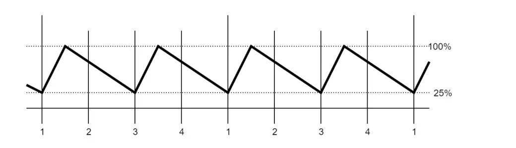
RGB colour
Pads and fader buttons can also be set to a custom colour using the following SysEx Regular SKUs:
- Hex: F0h 00h 20h 29h 02h 13h 01h 43h <padID> <R> <G> <B> F7h
- Dec: 240 0 32 41 2 19 1 67 <padID> <R> <G> <B> 247
Mini SKUs:
- Hex: F0h 00h 20h 29h 02h 13h 01h 43h <padID> <R> <G> <B> F7h
- Dec: 240 0 32 41 2 19 1 67 <padID> <R> <G> <B> 247
Controlling the screen
Concepts
- Stationary display: A default display which is shown unless any event requires a different display to be temporarily shown above it.
- Temporary display: A display triggered by an event, persisting for the length of the display timeout user setting.
- Parameter name: Used in association with a control, showing what it is controlling. Unless provided by messages (SysEx), typically this is the MIDI entity (such as note or CC).
- Parameter value: Used in association with a control, showing the current value of it. Unless provided by messages (SysEx), this is the raw value of the MIDI entity controlled (such as a number in range 0 – 127 in case of a 7 bits CC).
Configure displays
Regular SKUs:
- Hex: F0h 00h 20h 29h 02h 14h 04h <target> <config> F7h
- Dec: 240 0 32 41 2 20 4 <target> <config> 247
Mini SKUs:
- Hex: F0h 00h 20h 29h 02h 13h 04h <target> <config> F7h
- Dec: 240 0 32 41 2 19 4 <target> <config> 247
Once a display is configured for a given target, it can be triggered.
Targets
- 00h – 1Fh: Temp. display for Analogue controls (same as CC indices, 05h-0Dh: Faders, 15h-1Ch: encoders)
- 20h: Stationary display
- 21h: Global temporary display (can be used for anything unrelated to the Analogue controls)
- 22h: DAW pad mode’s displayed name (Field 0, empty: default)
- 23h: DAW Drum pad mode’s displayed name (Field 0, empty: default)
- 24h: Mixer encoder mode’s displayed name (Field 0, empty: default)
- 25h: Plugin encoder mode’s displayed name (Field 0, empty: default)
- 26h: Sends encoder mode’s displayed name (Field 0, empty: default)
- 27h: Transport encoder mode’s displayed name (Field 0, empty: default)
- 28h: Volume fader mode’s displayed name (Field 0, empty: default)
Config
The <config> byte sets up the arrangement and operation of the display. 00h and 7Fh are special values: It cancels (00h) or brings up (7Fh) the display with its current contents (as MIDI Event, it is a compact way to trigger display).
- Bit 6: Allow Launchkey to generate Temp. Display automatically on Change (default: Set).
- Bit 5: Allow Launchkey to generate Temp. Display automatically on Touch (default: Set; this is the Shift + rotate).
- Bit 0-4: Display arrangement
Display arrangements:
- 0: Special value for cancelling display.
- 1-30: Arrangement IDs, see table below.
- 31: Special value for triggering display.
| ID | Description | Num | Fields | F0 | F1 | F2 |
| 1 | 2 lines: Parameter Name and Text Parameter Value | No | 2 | Name | Value | – |
| 2 | 3 lines: Title, Parameter Name and Text Parameter Value | No | 3 | Title | Name | Value |
| 3 | 1 line + 2×4: Title and 8 names (for encoder designations) | No | 9 | Title | Name1 | … |
| 4 | 2 lines: Parameter Name and Numeric Parameter Value (default) | Yes | 1 | Name | – | – |
![]() NOTE
NOTE
The arrangement is ignored for targets only setting names (22h(34) – 28h(40)), however, for changing trigger ability, it needs to be set non-zero (since the value 0 for these still acts for cancelling the display).
Setting text
Once a display is configured, the following message can be used to fill in the text fields.
Regular SKUs:
- Hex: F0h 00h 20h 29h 02h 14h 06h <target> <field> <text…> F7h
- Dec: 240 0 32 41 2 20 6 <target> <field> <text…> 247
Mini SKUs:
- Hex: F0h 00h 20h 29h 02h 13h 06h <target> <field> <text…> F7h
- Dec: 240 0 32 41 2 19 6 <target> <field> <text…> 247
The text uses the standard ASCII character mapping in the range 20h (32) – 7Eh (126) with the addition of the below control codes, which have been reassigned to provide additional non-ASCII characters.
- Empty Box – 1Bh (27)
- Filled Box – 1Ch (28)
- Flat Symbol – 1Dh (29)
- Heart – 1Eh (30)
Other control characters should not be used as their behaviour may change in the future.
Bitmap
The screen can also display custom graphics by sending a bitmap to the device.
Regular SKUs:
- Hex: F0h 00h 20h 29h 02h 14h 09h <target> <bitmap_data> 7Fh
- Dec: 240 0 32 41 2 20 9 <target> <bitmap_data> 127
Mini SKUs:
- Hex: F0h 00h 20h 29h 02h 13h 09h <target> <bitmap_data> 7Fh
- Dec: 240 0 32 41 2 19 9 <target> <bitmap_data> 127
The <target> can be either the Stationary display (20h(32)) or the Global temporary display (21h(33)). There is no effect on other targets.
The <bitmap_data> is of fixed 1216 bytes, 19 bytes for each pixel row, for a total of 64 rows (19 × 64 = 1216). The 7 bits of the SysEx byte encode pixels from left to right (highest bit corresponding to the leftmost pixel), the 19 bytes covering the 128 pixels width of the display (with five unused bits in the last byte).
Upon success, there is a response to this message, which is suitable for timing fluid animations (once receiving it, the Launchkey is ready to accept a next Bitmap message):
Regular SKUs:
- Hex: F0h 00h 20h 29h 02h 14h 09h 7Fh
- Dec: 240 0 32 41 2 20 9 127
Mini SKUs:
- Hex: F0h 00h 20h 29h 02h 13h 09h 7Fh
- Dec: 240 0 32 41 2 19 9 127
The display can be cancelled by either cancelling it explicitly (using the Configure Display SysEx or MIDI Event), or triggering the normal display (whose parameters are preserved while the bitmap is displaying).
NOTE
The firmware can only hold one bitmap in its memory at once.
Launchkey MK4 feature controls
Many of the Launchkey’s features can be controlled by MIDI CC messages sent on channel 7 and queried by sending the same message to channel 8. Reply messages confirming changes or answering queries will always be sent on channel 7
To enable or disable these controls in standalone mode, use the below messages.
Enable feature controls:
- Hex: 9Fh 0Bh 7Fh
- Dec: 159 11 127
Disable feature controls:
- Hex: 9Fh 0Bh 00h
- Dec: 159 11 0
In DAW mode, all feature controls are listening, but will not send the confirmation reply except for a few essential ones. In DAW mode, the above messages can be used to turn fully on all of them or revert to the DAW set.
| CC Number | Feature | Control Type |
| 02h: 22h | Arp Swing | 2’s complement signed 14 bits
percentage |
| 03h:23h | Tempo control | |
| 04h: 24h | Arp Deviate rhythm pattern | nibble-split bitmask |
| 05h: 25h | Arp Ties | nibble-split bitmask |
| 06h: 26h | Arp Accents | nibble-split bitmask |
| 07h: 27h | Arp Ratchets | nibble-split bitmask |
| 1Dh (#) | Pads layout select | |
| 1Eh (#) | Encoders layout select | |
| 1Fh (#) | Faders layout select | |
| 3Ch | Scale behaviour select | |
| 3Dh (#) | Scale tonic (root note) select | |
| 3Eh (#) | Scale mode (type) select | |
| 3Fh (#) | Shift | |
| 44h | DAW 14-bits Analogue output | On/Off |
| 45h | DAW Encoder Relative output | On/Off |
| 46h | DAW Fader Pickup | On/Off |
| 47h | DAW Touch events | On/Off |
| 49h | Arp | On/Off |
| 4Ah | Scale mode | On/Off |
| 4Ch | DAW Performance note redirect (When On, Keybed notes go to DAW) | On/Off |
| 4Dh | Keyboard Zones, mode | 0: Part A, 1: Part B, 2 : Split, 3: Layer |
| 4Eh | Keyboard Zones, split key | MIDI note on default octave keybed |
| 4Fh (*) | Keyboard Zones, Arp connection select | 0: Part A, 1: Part B |
| 53h | DAW Drumrack active colour | |
| 54h | DAW Drumrack On / Off (When Off, Drumrack remains in MIDI mode
while in DAW mode) |
|
| 55h | Arp Type (Up / Down etc.) | |
| 56h | Arp Rate (including Triplets) | |
| 57h | Arp Octave | |
| 58h | Arp Latch | On/Off |
| 59h | Arp Gate length | percentage |
| 5Ah | Arp Gate minimum | milliseconds |
| 5Ch | Arp Mutate | |
| 64h (*) | MIDI Channel, Part A (or Keybed MIDI Channel for SKUs not having
keyboard split) |
0-15 |
| 65h (*) | MIDI Channel, Part B (only used on SKUs having keyboard split) | 0-15 |
| 66h (*) | MIDI Channel, Chords | 0-15 |
| 67h (*) | MIDI Channel, Drums | 0-15 |
| 68h (*) | Keys velocity curve / Fixed velocity select | |
| 69h (*) | Pads velocity curve / Fixed velocity select |
CC Number Feature Control Type
| 6Ah (*) | Fixed velocity value | |
| 6Bh (*) | Arp velocity (whether Arp should take velocity from its note input or use
fixed velocity) |
|
| 6Ch (*) | Pad aftertouch type | |
| 6Dh (*) | Pad aftertouch threshold | |
| 6Eh (*) | MIDI Clock output | On/Off |
| 6Fh (*) | LED brightness level | (0 – 127 where 0 is min, 127 is max) |
| 70h (*) | Screen brightness level | (0 – 127 where 0 is min, 127 is max) |
| 71h (*) | Temporary display timeout | 1/10 sec units, minimum of 1 sec at 0. |
| 72h (*) | Vegas mode | On/Off |
| 73h (*) | External Feedback | On/Off |
| 74h (*) | Pads power-on default mode select | |
| 75h (*) | Pots power-on default mode select | |
| 76h (*) | Faders power-on default mode select | |
| 77h (*) | Custom Mode Fader pick-up | 0: Jump, 1: Pickup |
| 7Ah | Chord Map Adventure setting | 1-5 |
| 7Bh | Chord Map Explore setting | 1-8 |
| 7Ch | Chord Map Spread setting | 0-2 |
| 7Dh | Chord Map Roll setting | 0-100 milliseconds |
Nibble-split controls use the least significant nibble of two CC values to create an 8-bit value. The first CCs value becomes the most significant nibble.
- Features marked with (*) are non-volatile, persisting across power cycles.
- Features marked with (#) are always fully enabled in DAW mode.
Documents / Resources
 |
LAUNCHKEY MK4 MIDI Keyboard Controllers [pdf] Instruction Manual MK4 MIDI Keyboard Controllers, MK4, MIDI Keyboard Controllers, Keyboard Controllers, Controllers |


