Labkotec D04222BE-5 Communication Unit Instruction Manual
OVERVIEW
The Labcom 220 communication unit is designed for the monitoring of industrial, domestic, and environmental engineering measurements remotely. Typical applications include oil separator alarms, tank sur- face level measurements, as well as pumping station and property monitoring

Labcom 220 sends alarm and measurement data in text messages ei- ther directly to the users’ mobile phones or to the LabkoNet® server via GPRS connection to be stored and shared with other parties
You can modify the unit settings with your mobile phone whenever necessary.
You can also specify when measurement results are to be sent and to which mobile numbers. You can also query the results using a text message.
Alarms are triggered if the specified alarm thresholds (upper or lower) are reached, or if the state of a digital input changes.
This installation and user guide contains instructions for the installa- tion, commissioning, and use of the communication unit.
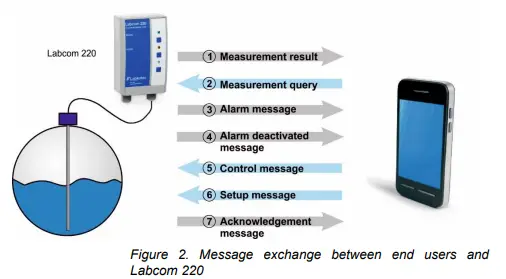
Labcom 220 and mobile phones
The figure below illustrates the message exchange between users and the Labcom 220 communication unit. All messages are sent as text messages. These are detailed later on in this document.
You can store two types of mobile numbers in the unit:
- End user numbers to which measurement and alarm messages are sent. These mobile numbers can also be used to query meas- urement
- Administrator numbers can be used to change the unit No measurement or alarm messages are sent to these mobile numbers, but they can be used for sending measurement queries.
NOTE! If you want to use the same mobile phone for receiving meas- urement and alarm messages and for specifying unit settings, you must specify the applicable mobile number both as an end user and an administrator number.
Labcom 220 and LabkoNet®
Labcom 220 can be connected to an online LabkoNet® monitoring system. Using the LabkoNet® system alongside mobile phones brings various advantages, including constant connection monitoring as well as measurement and alarm data storing and visual presentation.
Alarm and measurement data from measurement points is transferred to the LabkoNet® server through the communication unit over the GSM network. The server stores the data into a database from which it can later be accessed for reporting purposes, for example.
The server also checks the data of each measurement channel that is sent by the unit, converts it into the applicable format, and checks for possible alarm threshold violations. If it detects any violations, it sends the alarm data to the predefined email addresses as email messages and mobile numbers as text messages.
End users can also view measurement data in numerical or graphical format on a standard Internet browser online at www.labkonet.com with their user credentials.\
INSTALLATION AND COMMISSIONING
Installing the enclosure
The Labcom 220 unit enclosure is wall-mounted.
Open the cover of the enclosure
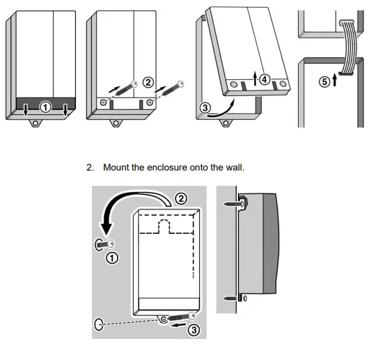
Drive the upper screw into the wall, hang the enclosure on it, and then drive the lower screw into the wall.
- Make the required connections according to the instructions in Chapter 2.2.
- Install the SIM card into the unit according to the instructions in Chapter 2.2.
- Close the cover of the enclosure.
Installation and Operating Instructions

Electrical connections
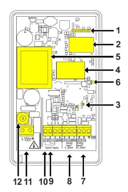
The figure below shows the electrical connections and other key com- ponents of the Labcom 220 unit.
Legend:
- Cable connection for the user interface
- 2G/3G modem
- 2G/3G modem signal light
- SIM card holder
- Transformer
- Reset button
- Analogue input 2, 4…20 mA
- Analogue input 1, 4…20 mA
- Digital input 2
- Digital input 1
- Mains input, 230 VAC
- Fuse 125 mAT
Connecting the unit to the mains supply
The operating voltage of the unit is 230 V, 50/60 Hz. The maximum connected load is 4 VA.
Connect the voltage to the terminals marked L and N (see the figure above). Use a dedicated feed from the distribution board, if possible. The unit is equipped with a 125 mAT distribution fuse (5×20 mm, glass tube).
NOTE! An isolating switch (250 VAC/1 A), which isolates both termi- nals (L1, N), must be installed to the supply voltage line near the unit to make use and maintenance easier. The switch must be labelled as the unit’s isolating switch. A standard plug can be used as the isola- tion switch.
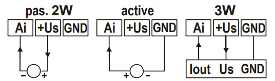
Connecting the sensors
The Labcom 220 unit is equipped with two 4…20 mA analogue inputs.
The unit provides a supply voltage of about 24 VDC (+Us) for a pas- sive 2-wire transmitter (pass. 2W) or 3-wire transmitter (3W). Alternatively, you can connect an active 2-wire transmitter that obtains its power supply from some other system to the analogue input.
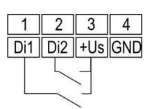
Connecting the digital inputs
The Labcom 220 unit has two digital current sinking inputs (switch in- puts). These are powered by a 20…28 VDC supply voltage, provided by the unit. The current is limited to about 200 mA. All digital and ana- logue inputs share the same voltage source and current limit
Cabling
To ensure sufficient protection against interference, you should use screened instrumentation cables and, for analogue inputs, double- sheathed cables.
Install the unit as far as possible from units with relay controls and other cabling. Input cables should not be routed closer than 20 cm to other cabling. Keep the input and relay cabling separate from the measurement and communications cabling.
Use single point earthing, if possible.
Installing the SIM card
Labcom 220 can be used with a SIM card of all the common 2G/3G operators.
- Install the SIM card acquired for the Labcom 220 communication unit to your own mobile phone and check that you can use it to send and receive text messages.
- Disable the PIN code query from the SIM card using your mobile
- Open the Labcom 220 SIM card holder by sliding the cover of the holder to right and then lifting the cover up. Install the SIM card with its metal contacts facing down and lock the card in place by sliding the cover of the holder to
Commissioning
All Labcom 220 commissioning procedures are carried out using text messages. You can use the following order, for example:
- Specify the end user mobile numbers (TEL).
Alarms and scheduled measurement messages are sent to these numbers. They can also be used to query the unit status (‘M’ que- ry). - Specify the administrator mobile numbers (OPTEL).
Once you have specified the administrator mobile numbers, you can only modify unit settings from one of these numbers. If no administrator mobile numbers have been specified, you can modi- fy the unit settings from any number. - Specify a name for the unit (NAME).
The name is displayed at the start of every message sent by the unit. - Specify the parameters for the measurements and digital inputs (AI and DI messages).
- Specify common (ALTXT) and measurement-specific alarm mes- sages (AIALTXT).
You may also find the following settings useful: - Specify the transmission time for scheduled measurement mes- sages (TXD).
- Specify the time (CLOCK).
The following chapter contains more details on the above-mentioned settings. It also covers all other unit settings.
Labkotec is taking care GPRS communication settings when Labcom 220 is connecting to Labkonet system.
OPERATION
Labcom 220 sends alarm and measurement data in text messages ei- ther directly to the users’ mobile phones or to the LabkoNet® server via GPRS connection to be stored and shared with other parties
You can modify the unit settings with your mobile phone whenever necessary.
You can also specify when measurement results are to be sent and to which mobile numbers. You can also query the results using a text message.
Alarms are triggered if the specified alarm thresholds (upper or lower) are reached, or if the state of a digital input changes.
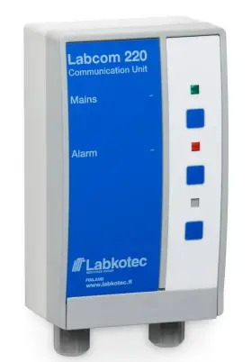
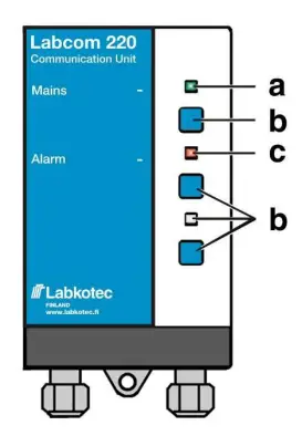
Control panel
| Signal light/button | State | Description |
| Green (a) | On | The unit is fully operational. |
| Red (c) | On | Measurement out-of-range alarm or digital input alarm |
| Blinks | Sensor connection fault or meas- urement value out of normal meas- urement range | |
| LED or button (b) | – | Not in use. |
MESSAGES AND REPLIES
- Mobile numbers
Adding mobile numbers for end users and administrators
The ‘End user and administrator mobile numbers’ setup message con- tains the following fields, separated by a white space:
| Field | Description |
| TEL or OPTEL | TEL = ‘End user mobile numbers’ message identifier
OPTEL = ‘Administrator mobile numbers’ message identifier |
| <No.> | The mobile number in international format
You can send all numbers accepted by the unit in one message (provid- ed that the standard message length of 160 characters is not exceeded). You can specify up to ten (10) end user mobile numbers. You can specify up to five (5) administrator mobile numbers. The unit saves the numbers in the first available memory slots in the order it receives them. If the message contains more than ten numbers or if no memory slots are free, the unit does not save the excess phone numbers. |
The following sample message
TEL. +35840111111 +35840222222 +35840333333
adds three end user mobile numbers to the unit. The unit sends the following reply (with one previously saved end user mobile number in the memory):
<UnitName> TEL. 1:+3584099999 2:+35840111111
3:+35840222222 4:+35840333333
The unit’s reply message format is as follows:
<UnitName> TEL <memory_slot>:<No.>
The message lists memory slot/number pairs for all end user mobile numbers stored in the memory.
To query the end user mobile numbers stored in the unit, send the fol- lowing message:
TEL.
To query the administrator mobile numbers stored in the unit, send the following message:
OPTEL
Deleting end user and administrator mobile numbers
Use the ‘Delete end user and administrator mobile numbers’ message to remove mobile numbers from the unit. The message contains the following fields, separated by a white space.
| Field | Description |
| DELTEL or DELOPTEL | DELTEL = ‘End user mobile numbers’ message identifier
DELOPTEL = ‘Administrator mobile numbers’ message identifier |
| <Memo- rySlotNum- ber> | The memory slot of the stored mobile number. You can use the TEL and OPTEL queries to find out the memory slot numbers. If you want to enter more than one memory slot number, separate the numbers with a white space. |
The following sample message
DELTEL 1 2
deletes the end user mobile numbers from memory slots 1 and 2. The third end user mobile number in the memory remains in its current slot.
The unit replies with a message listing the remaining numbers.
<UnitName> TEL. 3:+3584099999
Basic settings during commissioning
Specifying the unit/target name
Use the ‘Unit name’ message to specify a name for the unit. Once set, all messages that the unit sends start with the specified name. The message contains the following fields, separated by a white space.
| Field | Description |
| NAME | ‘Unit name’ message identifier |
| <UnitName> | The name of the unit or target. Maximum length: 20 characters. |
The following sample message
NAME AlarmUnitis acknowledged by the unit with the following message:
AlarmUnit NAME AlarmUnit
The unit’s reply message format is as follows:
<UnitName> NAME <UnitName>
Note! The ‘Unit name’ message can also contain white spaces. For example:Labcom 220
To find out the name of the unit, send the following message:NAME
Specifying the measurement message schedule
Use the ‘Measurement message schedule’ message to specify the transmission interval and time for the measurement messages sent by the unit. The message contains the following fields, separated by a white space.
| Field | Description |
| TXD | ‘Measurement message schedule’ message identifier |
| <Interval> | Measurement message transmission interval in days |
| <Time> | Measurement message transmission time format (hh:mm), where hh = hours
mm = minutes You can specify a maximum of six (6) daily transmission times. These must be separated with a white space in the ‘Measurement message schedule’ message. |
4.2.3 Setting the time
The following sample message
TXD 1 8:15 16:15
sets the unit to send measurement messages daily at 8:15 am and 4:15 pm.
The unit sends the following reply:
AlarmUnit TXD 1 8:15 16:15
The unit’s reply message format is as follows:
<UnitName> TXD <Interval> <Time>
To find out the transmission interval, send the following message:
TXD
To remove transmission times, specify the time as 25:00.
Use the ‘Set time’ message to modify the unit’s time setting. The mes- sage contains the following fields, separated by a white space.
| Field | Description |
| CLOCK | ‘Set time’ message identifier |
| <Date> | Enter the date in the following format: dd.mm.yyyy, where dd = date
mm = month yyyy = year |
| <Time> | Enter the time in the following format: hh:mm, where hh = hours
mm = minutes |
The following sample message
CLOCK 16.11.2009 8:00
sets the date on the unit clock as 16 November 2009 and the time as 8 am.
The unit sends the following reply:
<UnitName> 16.11.2009 8:00
To find out the time, send the following message:
CLOCK
NOTE! If the unit has been disconnected from the mains supply for an extended period of time, you must reset the time.
Querying the signal strength
To find out the signal strength of the 2G/3G modem, send the follow- ing message:
CSQ
The unit’s reply message format is as follows:<UnitName> CSQ 25.4
The signal strength range is from 0 to 31. If the value is below 11, the connection may be insufficient for sending messages. If the signal strength is 99, there is no connection to the base station.
Measurement settings
Specifying measurements
Use the ‘Set measurement’ message to specify the name, scaling, units, alarm thresholds, and alarm delays for measurements connect- ed to the unit’s analogue inputs. The message contains the following fields, separated by a white space.
| Field | Description |
| AI<n> | ‘Set measurement’ message identifier The identifier describes the unit’s physical measurement input.
Accepted values: AI1 and AI2. |
| <AInName> | Free-form text for the measurement. The name of the measurement is used as the measurement identifier in measurement and alarm mes- sages. See Chapter Measurement messages, for example. |
| <4mA> | The measurement value provided by the unit when the sensor current is 4 mA. (scaling) |
| <20mA> | The measurement value provided by the unit when the sensor current is 20 mA. (scaling) |
| <Unit> | The unit of the measurement (after scaling). |
| <Lo-
werThreshol d> |
The value of the lower alarm threshold (according to the scaling per- formed above). For details on how to specify the lower alarm threshold texts, see Chapter 4.5.2. |
| <Up-
perThreshol d> |
The value of the upper alarm threshold (according to the scaling per- formed above). For details on how to specify the upper alarm thresh- old texts, see Chapter 4.5.2. |
| <Delay> | The measurement’s alarm delay in seconds. The alarm is triggered if the measurement remains outside the range throughout the specified delay. The maximum delay is 34,464 seconds (~ 9 h 30 min). |
The following sample message
AI1 WellLevel 20 100 cm 30 80 60
sets up the measurement connected to analogue input 1 as follows:
- The name of the measurement is ‘WellLevel’.
- The value 20 (cm) corresponds to the sensor value of 4 mA.
- The value 100 (cm) corresponds to the sensor value of 20
- The unit of the measurement is cm.
- A lower threshold alarm message is sent when the level of the well drops below 30 (cm).
- An upper threshold alarm message is sent when the level of the well rises above 80 (cm).
- The alarm delay is 60
Specifying the measurement zero
To specify the measurement zero send the following message:
AI<n>ZEROSET
where <n> is the number of the applicable measurement channel.
You should specify the zero reference manually if the sensor fails to point to exactly zero when it should, for example. The message sets the surface level to 0 for the presently measured current message.
The unit replies with a message containing the difference (off-set) be- tween the set zero and the minimum value of the measurement set with the AI<n> message in the applicable unit of measurement.
AI<n>ZEROSET OK. OFFSET <OffSet> <UnitOfMeas-urement>
Specifying the surface level
Use the LEVELSET message to specify the desired value for the Lab- com 220 surface level measurement. This setting scales the surface level measurement linearly across the entire measurement range in relation with the set zero and the surface level set with the LEVELSET message.
Place the sensor to a desired depth in the liquid you want to measure, for example, before sending the following message:
AI<n>LEVELSET <SurfaceLevel>
where <n> is the number of the applicable measurement channel.
The unit of measurement you use for the surface level must be the same as in the AI<n> message sent earlier.
Specifying tank details (level/volume conversion)
Use the LEVEL message to convert the tank’s surface level meas- urement into volume data.
Once you have set the tank details, the measurement data is sent to users in the specified unit of volume. To see the surface level in the original format, specified with the ‘AI<n>’ message, use the LEVEL message.
The message contains the following fields, separated by a white space.
| Field | Description |
| AI1CONV or AI2CONV | AI1CONV = Tank details for measurement 1.
AI2CONV = Tank details for measurement 2. |
| <Type> | The type of the tank (range: 0–3).
0 = The level/volume conversion is disabled. 1 = Horizontal cylinder tank. 2 = Horizontal cylinder tank with rounded ends. |
| <Height> | The height of the tank is the same unit of measurement as in the AI<n> message. |
| <Volume> | The total volume of the tank corresponding to the height of the tank. |
| <Unit> | The unit of the volume. |
| <Lo-
werAlarmTh reshold> |
The volume for the lower alarm threshold. |
| <UpperA- larmThresh old> | The volume for the upper alarm threshold. |
| <Delay> | The alarm delay in seconds. |
The following sample message
AI1CONV 2 1700 10000 litres 500 9000 60
specifies the conversion parameters for the analogue measurements of a type 2 tank. The parameters are as follows:
Tank height: 1700 (mm)
Tank volume: 10000
Unit of the volume: litres
Lower alarm threshold: 500 (litres)
Upper alarm threshold: 9000 (litres)
Delay: 60 (seconds)
The unit’s reply message format is as follows:<UnitName> AI1CONV 2 1700 10000 litres 500 900060
To find out stored tank details, send the following message:
AI1CONV
To disable volume conversion, send the following message:
AI1CONV 0
The message above does not delete previously saved tank details. Send the
AI1CONV 1
message to enable a previously used conversion for a horizontal cyl- inder tank.
Activating filling detection
Labcom 220 includes automatic filling detection. Using this feature, however, requires specific measurement actions.
The unit considers a situation where the volume of the substance in the tank increases at least 2.5% of the tank volume in 5 minutes or less as filling.
The unit sends a message containing filling data 15 minutes after the filling has stopped. If the filling is suspended but then continues within 15 minutes, the entire event is reported in one message.
The activation message is described below. You must specify the tank details (see above) before using this feature.
| Field | Description |
| USEFILL | Message identifier |
| <Input 1> | Filling detection state for measurement 1: 0= disabled, 1 = enabled. |
| <Input 2> | Filling detection state for measurement 2: 0= disabled, 1 = enabled. |
The message
USEFILL 0 1
disables filling detection for measurement 1 and enables it for meas- urement 2.
When the unit detects that filling has started, it sends the following message:
<UnitName> <MeasurementName> FILLING START <In- itialVolume> <UnitOfMeasurement>
Once the filling has stopped, the unit sends the following report:
<UnitName> <MeasurementName> FILLING <FilledAmount>
<UnitOfMeasurement>, VOLUME AFTER FILLING <Final- Volume> <UnitOfMeasurement>
Querying the surface level
If you have activated the level/volume conversion in Labcom 220, the unit uses the specified unit of volume in all messages. You can still find out the surface level by sending the following message:
LEVEL
The unit’s reply message format is as follows:
<UnitName> <Measurement1Name> <SurfaceLevel>
<UnitOfMeasurement>, <Measurement2Name> <Surface- Level> <UnitOfMeasurement>
Filtering measurement values
A single measurement value does not provide an accurate picture in situations where the surface level keeps changing suddenly, so you may want to filter the analogue measurements in order to obtain more precise data. Situations with sudden fluctuations include lake surface level measurements where waves cause the measurement result to vary significantly within just a few seconds.
| Field | Description |
| AI<n>MODE | ‘Measurement value filtering’ message identifier, where <n> = 1 or 2. The identifier describes the unit’s physical measurement input.
Accepted values: AI1MODE and AI2MODE. |
| <Mode> | Filtering mode.
0 = The so-called digital RC filtering is enabled on the analogue chan- nel, that is, the filtering factor <Par> is used to influence the measure- ment result to even out the difference between consequent results. |
| <Par> | Filtering factor. See below.
If the mode is 0, the <Par> is a filtering factor between 0.01 and 1.0. The maximum filtering value is 0.01. No filtering is performed when <Par> is 1.0. |
You need to enable filtering separately for each analogue input.
To enable filtering/averaging for an analogue input, send the following message:
AI<n>MODE <Mode> <Par>
The following sample message
AI1MODE 0 0.8
the filtering factor 0.8 is used to influence the measurement result to even out the difference between consequent results.
To find out the filtering mode and value of an analogue input, send the following message:
AI<n>MODE
where <n> is the number of the applicable input. The unit’s reply message format is as follows:
<UnitName> TXD AI<n>MODE <Mode> <Par>
Note! If you have not specified an AI<n>MODE setting for the chan- nel, the default setting is mode 0 (digital RC filter) with a factor of 0.8.
Specifying hysteresis thresholds for analogue inputs
If necessary, you can specify a hysteresis threshold for an analogue input. The threshold is the same for the lower and upper alarm thresholds. The upper threshold alarm is cancelled when the input value drops by at least the hysteresis value below the set alarm threshold, and vice versa for the lower threshold. To specify the hyste- resis threshold, send the following message:
AI<n>HYST <HysteresisThreshold> where <n> is the number of the analogue input. Sample message:
AI1HYST 0.1
The unit of measurement used for the hysteresis threshold is the unit set for the threshold in question.
Specifying the number of used decimals
To change the number of used decimals in measurement and alarm messages, send the following message:
AI<n>DEC <NumberOfDecimalsFrom0To9>
The following sample message changes the number of decimals to three:
AI1DEC 3
The unit acknowledges the setting with the following reply:
<UnitName> AI1DEC 3
Digital inputs
Specifying digital inputs
Use the ‘Set digital input’ message to send digital input details to the unit. The message contains the following fields, separated by a white space.
| Field | Description |
| DI<n> | ‘Set digital input’ message identifier The identifier describes the unit’s physical digital input.
Accepted values: DI1 and DI2. |
| <DInName> | Free-form text for the digital input. The name of the digital input is used as the digital input identifier in measurement and alarm mes- sages. See Chapter Measurement messages, for example. |
| <On> | Text describing the active state of the digital input. |
| <Off> | Text describing the inactive state of the digital input. |
| <Mode> | The operating mode of the digital input. 0 = active state triggers alarm
1 = inactive state triggers alarm |
| <Delay> | The alarm delay in seconds. The maximum delay is 34 464 seconds (~ 9 h 30 min).
NOTE! When the delay of digital input is set to 600 seconds or more and the alarm is activated, delay for alarm de-activation is not the same as for activation. In this case, alarm is de-activated in 2 sec- onds after the input has returned to the inactive state. This makes e.g. supervision of maximum running time of pumps possible. |
The following sample message
DI1 DoorSwitch on off 0 20sets up the unit’s digital input as follows:
- The unit sends an alarm message 20 seconds after the door switch in digital input 1 is activated. The alarm message for- mat is as follows:<UnitName> <AlarmText> DoorSwitch on
- When the alarm is cancelled, the message format is as fol- lows:<UnitName> <AlarmCancelledText> DoorSwitch off
Enabling pulse counting
You can enable pulse counting for the unit’s digital inputs by setting the following parameters:
| Field | Description |
| PC<n> | ‘Pulse counting’ message identifier (PC1 or PC2). |
| <PulseCounter- Text> | The name of the pulse counter in the unit’s reply message. |
| <Unit> | The unit of measurement, for example pcs. |
| <Divisor> | You can specify that the counter is incremented only with every 5th or 7th pulse, for example. The divisor can be any integer between 1 and 65534. |
| <FilteringDe- lay> | The time the digital input must be active before the counter registers the pulse. The used unit of measurement is ms. You can specify any value between 1 and 254 ms. |
Sample message for enabling pulse counting:PC2 Pump2On times 1 100
The unit replies to this message as follows:<UnitName> PC2 Pump2On times 1 100Sample pulse counting measurement message:
<UnitName> Pump2On 4005 times
To clear the pulse counter, send the following message to the unit:
PC<n>CLEAR
For example:
PC2CLEAR
To clear all pulse counters simultaneously, send the following mes- sage:
PCALLCLEAR
Enabling active state counters
You can enable counters that monitor how long digital inputs are ac- tive. The counter is incremented every second that the digital input is in the ‘inactive’ state. The message format is as follows:
| Field | Description |
| OT<n> | Active state counter identifier, where <n> is the number of the digi- tal input. |
| <OTName> | The name of the counter in the measurement message. |
| <Unit> | The measurement unit in the reply message. |
| <Divisor> | The number used to divide the figure in the reply message. |
The sample message below sets the divisor for digital input 2 as one and the unit as seconds. The counter is labelled ‘Pump2’.
OT2 Pump2 seconds 1
Please note that the unit is just a text field, and cannot be used for unit conversion. The divisor is provided for that purpose.
To disable a counter, send the following message:
OT<n>CLEAR
Alarms
To disable all counters, send the following message:
OTALLCLEAR
Use the ‘Alarm text’ message to specify the text that the unit uses at the beginning of alarm messages when alarms are triggered and can- celled. You can use a different text for both. The message contains the following fields, separated by a white space.
| Field | Description |
| ALTXT | ‘Alarm text’ message identifier |
| <AlarmOn>. | Alarm message text when an alarm is triggered. The text must end in a period. |
| <AlarmOff> | Alarm message text when an alarm is cancelled. |
The specified alarm text (either <AlarmOn> or <AlarmOff>) is added to the alarm message between the unit name and alarm cause. For more details, see Chapter Alarm messages.
Sample message:
ALTXT ALARM. ALARM CANCELLED
The unit’s reply message format is as follows:
<UnitName> ALTXT ALARM. ALARM CANCELLED
The corresponding alarm message would then be as follows:
AlarmUnit ALARM <MeasurementName> …
Specifying alarm threshold texts
Use the ‘Alarm threshold texts’ message to specify the text that indi- cates the cause of the alarm. The text is used in alarm triggered and alarm cancelled messages. When the measurement drops below the lower threshold, the unit includes the applicable text in the alarm mes- sage. The message contains the following fields, separated by a white space.
| Field | Description |
| AI<n>ALTXT | ‘Alarm threshold texts’ message identifier. The message for meas- urement 1 starts with ‘AI1ALTXT’, while ‘AI2ALTXT’ is used for measurement 2. |
| <Lo-
werThreshol dText>. |
The text included in the message sent when a lower threshold alarm is triggered or cancelled. The text must end in a period. By default, the value of this field is ‘Low Limit’. |
| <Up-
perThreshol dText> |
The text included in the message sent when an upper threshold alarm is triggered or cancelled. By default, the value of this field is ‘High Limit’. |
The measurement alarm threshold texts are included in the alarm message after the name of the measurement input that caused the alarm. For more details, see Chapter Alarm messages.
Sample setup message:
AI1ALTXT LowerThreshold. UpperThreshold
The unit’s reply message format is as follows:
<UnitName> AI1ALTXT LowerThreshold. Upper- Threshold
The corresponding alarm message would then be as follows:
AlarmUnit ALARM Measurement1 UpperThreshold 80 cm
Specifying alarm recipients
Use the ‘Alarm recipients’ message to specify recipients for the mes- sages. By default, all messages are sent to all users. The message contains the following fields, separated by a white space.
| Field | Description |
| ALMSG | ‘Alarm recipients’ message identifier |
| <MemorySlot> | The memory slot of the mobile number stored in the unit. (Use the TEL message to find out the slot numbers.) |
| <Messages> | The sent messages. The following values are available: 1 = only alarms and measurements
2 = only cancelled alarms and measurements 3 = alarms, cancelled alarms, and measurements 4 = only measurements, no alarms or cancelled alarms 8 = no alarms or measurements |
The following sample message
ALMSG 2 1
specifies the end user in memory slot 2 as the recipient of alarms and measurements.
The unit’s reply to the sample message (the reply includes the mobile phone number stored in memory slot 2):
AlarmUnit ALMSG +3584099999 1
The unit’s reply message format is as follows:
<UnitName> ALMSG <MobileNumberInMemorySlot>
<Messages>
To find out alarm message recipient information on all end users, send the following message:ALMSG
Other settings
Enabling channels
Use the ‘Enable channel’ message to enable measurement channels. Please note that channels specified with the ‘Set measurement’ or ‘Set digital input’ messages are automatically enabled.
The message contains the following fields, separated by a white space.
| Field | Description |
| USE | ‘Enable channel’ message identifier. |
| AI<n> | The number of the analogue channel you want to enable. You can ena- ble all analogue channels in one message.
Accepted values: AI1 and AI2. |
| DI<n> | The number of the digital channel you want to enable. You can enable all digital channels in one message.
Accepted values: DI1 and DI2. |
Disabling channels
The unit replies to the setup message and query (USE message with- out any parameters) by sending the new settings as defined in the setup message and by adding the unit name to the beginning of the message.
The sample message below enables measuring channels 1 and 2 and digital inputs 1 and 2 on the unit.
USE AI1 AI2 DI1 DI2
Use the ‘Disable channels’ message to delete existing measurement channels. The message contains the following fields, separated by a white space.
| Field | Description |
| DEL | ‘Disable channel’ message identifier. |
| AI<n> | The number of the analogue channel that you want to disable. You can disable all analogue channels with one message.
Accepted values: AI1 and AI2. |
| DI<n> | The number of the digital channel you want to disable. You can disable all digital channels with one message.
Accepted values: DI1 and DI2. |
The unit replies to the setup message by sending the identifiers of the remaining channels and adding the unit name to the beginning of the message.
The sample message below disables measuring channel 2 and digital input 1 on the unit.
DEL AI2 DI1
The unit replies with a message containing the remaining channels. For example:<UnitName> USE AI1 DI2
The unit replies to a DEL message without parameters by listing the channels currently in use.
Querying the software version
To find out the software version of the unit, send the following mes- sage:
Clearing text fields
VER The unit’s reply message format is as follows:<UnitName> LC220 v<Version> <Date> <Time> IAR AVR V<Version>For example:
LC220 v4.00 Jun 13 2018 11:59:51 IAR AVR V7.10
To clear a text field, replace the applicable value with a question (?) mark. You can clear values you have specified using text messages. To clear the unit name, for example, send the following message:NAME ?
MESSAGES TO END USERS SENT BY THE UNIT
Measurement queries
This chapter describes the messages sent by the Standard edition of the Labcom 220 communication unit. Customer-specific messages, if applicable, are detailed in a separate document.
To query measurement values and digital input states, send the fol- lowing message:
MThe unit replies with a message listing the values of all enabled chan- nels.
Measurement messages
The unit sends measurement messages to end user mobile numbers either as specified with the Measurement message schedule message or as a reply to a Measurement query message.
The measurement message contains the following fields, separated by a white space. Only data of enabled channels is included. The data of each measurement and digital input data is separated with a com- ma (excluding the last one).
| Field | Description | |
| <UnitName> | If you have specified a name for the unit, it is included at the begin- ning of the message. | |
| <AInName>
<Value> <UnitOfMea- surement>, |
The name of the measurement channel, measurement result, and unit of each measurement. A comma is used to separate the data of different measurement channels. | |
| <AInName> | The name/text specified for measurement ‘n’. | |
| <Value> | The measurement result for measurement ‘n’. | |
| <UnitOfMea- surement> | The unit for measurement ‘n’. | |
| <DInName>
<State>, |
The name and state of each digital input. A comma is used to sepa- rate the data of different digital inputs. | |
| <DInName> | The name/text specified for the digital input. | |
| <State> | The state of the digital input. | |
| <PulseCoun- terName>
<Numbe- rOfPulses> <UnitOfMea- surement> |
If pulse counting has been enabled for any of the digital inputs, the value is shown in this field. The data of different counters is sepa- rated with a comma. | |
| <PulseCoun- terName> | The name of the counter. | |
| <Numbe- rOfPulses> | The number of pulses divided by the divisor. | |
| <UnitOfMea- surement> | The used unit of measurement. | |
| <ActiveSta- teCounter- Name> <Num- berOfPul- ses>
<UnitOfMea- surement> |
If active state counting has been enabled for any of the digital in- puts, the value is shown in this field. The data of different counters is separated with a comma. | |
| <Counter- Name> | The name of the counter. | |
| <Time> | The active state period of the digital input. | |
| <UnitOfMea- surement> | The used unit of measurement. | |
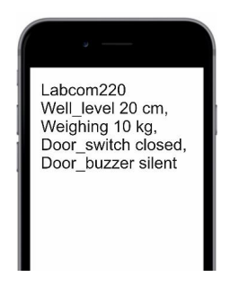
With the following sample message
Labcom220 Well_level 20 cm, Weighing 10 kg,
Door_switch closed, Door_buzzer silent
the unit reports that unit called Labcom220 has carried out the follow- ing measurements:
- The Well_level (for example Ai1) reading is 20 cm
- The Weighing (for example Ai2) reading is 10 kg
- The Door_switch (for example Di1) state is closed
- The Door_buzzer (for example Di2) state is silent
Note! If no unit name, the measurement name and/or unit have been specified, the measurement message leaves their placeholders emp- ty.
Specifying comma use in measurement messages
You can remove commas from messages sent to end users (namely measurement messages), if necessary. Use the following messages to modify the settings.
No commas
USECOMMA 0
Use commas (default setting)
USECOMMA 1
Alarm messages
Alarm messages are sent to end user mobile numbers only.
Alarm messages contain the following fields, separated by a white space
| Field | Description |
| <UnitName> | If you have specified a name for the unit with the NAME message, it is included at the beginning of the message. |
| <AlarmOn>. | The alarm text specified with the ALTXT message. For example, ALARM. |
| <AInName> or
<DInName> |
The name of the measurement or digital input that triggered the alarm. |
| <Cause> | The reason for the alarm (lower or upper threshold alarm) or the state text of the applicable digital input. |
| <Measure- mentValue> and <UnitOf- Measurement> | If the alarm was triggered by a measurement, the alarm message in- cludes the value and unit of the measurement. This field is not includ- ed in alarm messages triggered by digital inputs. |
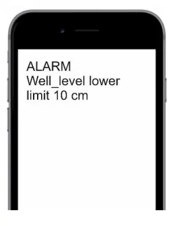
With sample message 1
ALARM Well_level lower limit 10 cmthe unit reports that:
- The well level measurement has dropped below the lower
- The measurement result is 10
With sample message 2 (with Labcom220 as the unit name)
Labcom220 ALARM Door_switch on
the unit reports that the alarm was triggered by an active door switch.
Note! If no unit name, alarm text, alarm or digital input name and/or unit have been specified, their placeholders are left empty in the alarm message. It is, therefore, entirely possible that the unit sends meas- urement alarm messages with just a measurement value or that digital inputs trigger alarm messages with no content.
Alarm cancelled messages
‘Alarm cancelled’ messages are only sent to end user mobile num- bers.
‘Alarm cancelled’ messages contain the following fields, separated by a white space.
| Field | Description |
| <UnitName> | If you have specified a name for the unit with the NAME message, it is included at the beginning of the message. |
| <AlarmOff> | The ‘Alarm cancelled’ text is specified with the ALTXT message. For example, ALARM CANCELLED. |
| <AInName> or
<DInName> |
The name of the measurement or digital input that triggered the alarm. |
| <Cause> | The reason for the alarm (lower or upper threshold alarm) or the state text of the applicable digital input. |
| <Measure- mentValue> | If the alarm was triggered by a measurement, the ‘Alarm can- celled’ message includes the value and unit of the measurement. This field is not included in the alarm messages triggered by digital inputs. |
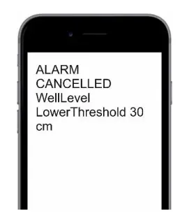
With the following sample message
ALARM CANCELLED WellLevel LowerThreshold 30 cmthe unit reports that:
- The lower threshold alarm for the well level measurement has been
- The measurement result is currently 30
With sample message 2 (with AlarmUnit as the unit name)
AlarmUnit ALARM CANCELLED DoorSwitch off the unit reports that the door switch is now inactive, and the alarm that was triggered when the switch was activated, has been cancelled.
SERVICE AND MAINTENANCE
PIN code
Provided that proper care is taken and the unit disconnected from the mains supply, the distribution fuse (marked 125mAT) may be replaced with an IEC 127 compliant, 5×20 mm/125 mAT glass tube fuse.
If you have forgotten the administrator mobile number or specified an incorrect one, you can change it using the unit’s 4-digit PIN code.
The factory setting for the PIN code is 1234.
Changing the PIN code
PIN <OldPIN> <NewPIN>
The following sample message
PIN 1234 1111
changes the PIN code from the factory setting of 1234 to 1111.
Resetting the administrator mobile number
To change the administrator mobile number, first send the following message:
SOPTEL <PIN> <YourMobileNumber>
This authorises your mobile number to modify the unit data. For example, the message
SOPTEL 1234 +358401234567
grants write rights to mobile number +358401234567.
After this step, you can register your mobile number as an administra- tor mobile number using the OPTEL message. For details, see Chap- ter 4.
Other problem situations
Other service and maintenance tasks must be carried out only by a qualified electrician who is authorised by Labkotec Oy.
In any problem situations, please contact Labkotec Oy’s service department.
APPENDIXES
Appendix 1 Technical specifications
| Labcom 220 | |
| Dimensions | 100 x 188 x 65 mm (W x H x D) |
| Enclosure | IP 30, material: ABS plastic |
| Cable bushings | 2 pcs M12 for cable diameter 3-6,5 mm |
| Operating environment | Temperature: -20ºC…+50ºC
Max. elevation above sea level 2,000 m Relative humidity RH 100% Suitable for indoor and outdoor use (protected from direct rain) |
| Supply voltage | 230 VAC, 50/60 Hz |
| Fuse | 125 mAT, IEC 127 5×20 mm |
| Power consumption | Max. 4 VA |
| Analogue inputs | 2 pcs, 10-bit. 4–20 mA active or passive, 24 VDC, max. 25 mA per input |
| Digital inputs | 2 pcs, 24 VDC |
| Relay outputs | – |
| Data communications | GSM text messages (SMS) and GPRS
Built-in 2G/3G modem 850/900/1800/1900/2100 MHz |
| Measurement and data transfer intervals | User defined |
| Electrical safety | EN 61010-1, Class II, CAT II/III, POLLUTION DEGREE 2 |
| EMC | EN IEC 61000-6-3 (emissions) EN IEC 61000-6-2 (immunity) |
| RED | EN 301 511
EN 301 908-1 EN 301 908-2 |

Read More About This Manual & Download PDF:
Documents / Resources
 |
Labkotec D04222BE-5 Communication Unit [pdf] Instruction Manual D04222BE-5 Communication Unit, D04222BE-5, Communication Unit, Unit |