TERACOM TSM400-4-TH Modbus Humidity and Temperature Sensor
Short description
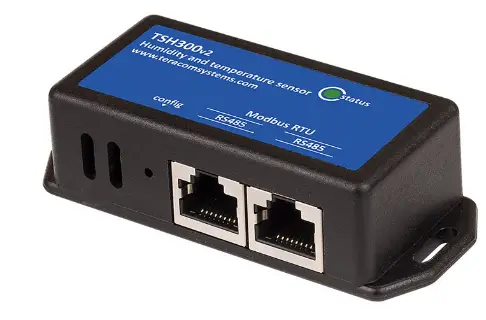
TSM400-4-TH is a humidity and temperature sensor that supports MODBUS RTU protocol over the RS-485 interface. A unique capacitive element is used for measuring relative humidity while the temperature is measured by a band gap sensor. Both sensors are seamlessly coupled to a 12-bit analog to digital converter. This results in superior signal quality. The TSM400-4-TH multi-sensor is housed in a slim plastic enclosure. The bottom part of the enclosure is suitable for installation on standard flush-mounted/cavity wall boxes ø68mm, with installation openings on 61 mm.
Features
- LED indicator for status of communication;
- Long-term stability based on digital signal processing;
- RS-485 interface carrying up to 32 nodes;
- Changeable bitrate and other communication parameters;
- Firmware update via the interface.
Applications
- Environmental quality monitoring and assessment for offices
- Server room and data centers humidity and temperature monitoring
- Smart ventilation systems
Specifications
- Physical characteristics
- Dimensions: 81 x 81 x 30 mm
Weight: 66 g
- Dimensions: 81 x 81 x 30 mm
- Environmental limits
- Operating temperature range: -20 to 60°C
- Operating relative humidity range: 5 to 95% (non-condensing)
- Storage temperature range: -20 to 60°C
- Storage relative humidity range: 5 to 95% (non-condensing)
- Ingress protection: IP20
- Power requirements
Operating voltage range (including -15/+20% according to IEC 62368-1): 4.5 to 26 VDC Current consumption: 25 mA@5VDC (Peak: 150 mA@5VDC) - Humidity measurements
- Accuracy (min): ±3.0 %RH (in 20 to 80 %RH range)
- Accuracy (max): ±5.0 %RH (in 5 to 95 %RH range)
- Resolution: 0.1 %RH
Recommended operating range is 20% to 80% RH (non-condensing) over –10 °C to 60 °C Prolonged operation beyond these ranges may result in a shift of sensor reading, with slow recovery time.
- Temperature measurements
- Accuracy (min): ±0.4 °C (in -10 to +60°C range)
- Accuracy (max): ±0.6 °C (in -20 to +60°C range)
- Resolution: 0.1 °C
- Warranty
Warranty period: 3 years
Pinout
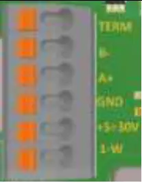 |
Pin | Description | UTP wires color |
| 1-W | Not used | ||
| +5÷30V | Positive power supply | Brown/White Tracer | |
| GND | Ground (negative) supply | Brown | |
| A+ | Line A+ of RS-485 | Blue/White Tracer | |
| B- | Line B- of RS-485 | Blue | |
| TERM | For termination, connect to B- |
Installation
Two-Wire MODBUS definition according to modbus.org: A MODBUS solution over a serial line should implement a Two-Wire electrical interface in accordance with EIA/TIA-485 standard. On such a Two-Wire topology, at any time one driver only has the right for transmitting. In fact, a third conductor must also interconnect all the devices of the bus – the common.
Attention
For proper operation of the interface, terminators (120 ohms resistors) must be installed at both ends of the bus. The device has a built-in 120-ohm resistor and to terminate the line, B and TERM must be shortened. A daisy-chained (linear) topology for multiple sensors should be used. UTP/FTP cables are mandatory for interconnection.
Installation tips
The location and the mounting position of the sensor have a direct effect on the accuracy of the measurement. The tips below will ensure good measuring results:
- Sensor shall be installed about 1.2-1.4 m above the floor;
- To avoid solar radiation, the sensor should not be installed next to windows or directly in the sunlight;
- Sensors shall be installed in a place with sufficient air circulation.
TSM400-4-TH sensor is intended for installation on a cavity wall box with 68mm diameter and 61 mm screw spacing. 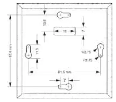
Status indicator
The status of the device is shown by a single LED, located inside the box:
- If the LED blinks for a period of 1 second, the sensor works properly;
- If the LED blinks for a period of 3 seconds, there isn‘t communication with the controller;
- If LED doesn‘t blink, there isn‘t a power supply.
Factory default settings
Disconnect the sensor from the bus (switch off the power supply). Press and hold the “config” button. Don’t release the button, connecting the sensor to the bus (switch on the power supply). The “status” LED will be ON for 3 seconds and after this will flash for 7 seconds. After the 10th second the LED will be ON. Release the button. The sensor will restart with factory default settings.
Firmware update
The firmware of the sensor can be updated with a Teracom controller which supports MODBUS RTU or MBRTU-Config software. For more details ask your dealer.
Modbus address table
|
Register name |
R/W |
FC |
PDU
Address (Decimal) |
Logical Address
(Decimal) |
Offset (Decimal) |
Data size |
Default |
Valid values |
| RS-485 address | R/W | 03/06 | 10 | 40011 | 40001 | 16-bit uns. integer | 1 | 1-247 |
| Baud rate* | R/W | 03/06 | 11 | 40012 | 40001 | 16-bit uns. integer | 19200 | 2400, 4800, 9600,
19200, 38400, 57600 |
| Parity, data, stop bits * | R/W | 03/06 | 12 | 40013 | 40001 | 16-bit uns. integer | 1 | 1=E81, 2=O81, 3=N81 |
| Data order | R/W | 03/06 | 13 | 40014 | 40001 | 16-bit uns. integer | 1 | 1=MSWF (MSW, LSW)
2=LSWF (LSW, MSW) |
| Sub-family number | R | 3 | 14 | 40015 | 40001 | 16-bit uns. integer | 1 | 0xC9 |
| FW version | R | 3 | 15 | 40016 | 40001 | 16-bit uns. integer | ||
| Vendor URL | R | 3 | 16 | 40017 | 40001 | 64 bytes UTF-8 | teracomsystems.com | |
| Float test value (MSWF) | R | 3 | 82 | 40083 | 40001 | 32-bit float | -9.9(0xC11E6666) | |
| Float test value (LSWF) | R | 3 | 84 | 40085 | 40001 | 32-bit float | -9.9(0xC11E6666) | |
| Signed integer test value | R | 3 | 86 | 40087 | 40001 | 16-bit sig. integer | -999(0xFC19) | |
| Signed integer test value
(MSWF) |
R | 3 | 87 | 40088 | 40001 | 32-bit sig. integer | -99999(0xFFFE7961) | |
| Signed integer test value
(LSWF) |
R | 3 | 89 | 40090 | 40001 | 32-bit sig. integer | -99999(0xFFFE7961) | |
| Unsigned integer test value | R | 3 | 91 | 40092 | 40001 | 16-bit uns. integer | 999(0x03E7) | |
| Unsigned integer test value
(MSWF) |
R | 3 | 92 | 40093 | 40001 | 32-bit uns. integer | 99999(0x0001869F) | |
| Unsigned integer test value
(LSWF) |
R | 3 | 94 | 40095 | 40001 | 32-bit uns. integer | 99999(0x0001869F) | |
| Temperature °C | R | 3 | 100 | 40101 | 40001 | 32-bit float | ||
| Humidity %RH | R | 3 | 102 | 40103 | 40001 | 32-bit float | ||
| Dew point °C | R | 3 | 104 | 40105 | 40001 | 32-bit float | ||
| Temperature °F | R | 3 | 400 | 40401 | 40001 | 32-bit float | ||
| Humidity %RH | R | 3 | 402 | 40403 | 40001 | 32-bit float | ||
| Dew point °F | R | 3 | 404 | 40405 | 40001 | 32-bit float | ||
| Temperature °C x 100 | R | 3 | 600 | 40601 | 40001 | 16-bit sig. integer | ||
| Humidity %RH x 100 | R | 3 | 601 | 40602 | 40001 | 16-bit uns. integer | ||
| Dew point °C x 100 | R | 3 | 602 | 40603 | 40001 | 16-bit sig. integer | ||
| Temperature °F x 100 | R | 3 | 1000 | 41001 | 40001 | 16-bit sig. integer | ||
| Humidity %RH x 100 | R | 3 | 1001 | 41002 | 40001 | 16-bit uns. integer | ||
| Dew point °C x 100 | R | 3 | 1002 | 41003 | 40001 | 16-bit sig. integer |
MSWF – Most significant word first – (bits 31 … 16), (bits 15 … 0); LSWF – Least significant word first – (bits 15 … 0), (bits 31 … 16); PDU address – Actual address bytes used in a Modbus Protocol Data unit
A value is returned for unavailable floating-point values (e.g. in case of measurement error)
- The settings will take effect after restarting the device by powering off, and power it on.
Recycling
Recycle all applicable materials. Do not dispose of regular household refuse. TSM400-4-TH_R1.0 – September 2022
Documents / Resources
 |
TERACOM TSM400-4-TH Modbus Humidity and Temperature Sensor [pdf] User Manual TSM400-4-TH Modbus Humidity and Temperature Sensor, TSM400-4-TH, Modbus Humidity and Temperature Sensor, Temperature Sensor, Sensor, Modbus Humidity, Humidity |
 |
TERACOM TSM400-4-TH Modbus Humidity and Temperature Sensor [pdf] User Manual TSM400-4-TH Modbus Humidity and Temperature Sensor, TSM400-4-TH, Modbus Humidity and Temperature Sensor, Modbus Humidity Sensor, Temperature Sensor, Humidity Sensor, Sensor |


