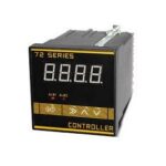
SON BEST SC7261B RS485 Interface Led Display Voltage C ontroller Video

SC7261B uses the standard RS485 bus MODBUS RTU protocol, easy access to PLC DCS, and other instruments or systems for monitoring DC5Vvoltage state quantities. The internal use of high precision sensing core and related devices to ensure high reliability and excellent long-term stability can be customized RS232, RS485, CAN,4 20mA, DC0~5V 10V, ZIG BEE, Lora, WIFI, GPRS, and other output methods.
Technical Parameters
| Technical parameter | Parameter value |
| Brand | SONBEST |
| Input Signal | DC0~5V voltage |
| Communication Interface | RS485 |
| Default baud rate | 9600 8 n 1 |
| Power | AC185~265V 1A |
| Running temperature | -40~80°C |
| Working humidity | 5%RH~90%RH |
WIRING METHOD IS bSIMPLE AND CLEAR
The wiring is simple and easy to understand, no complicated operation is required

HIGH SENSITIVITY INDUSTRIAL DESIGN
Every detail has undergone many manual tests and repeated revisions, just to bring you a better experience, and carefully create high-quality products

In Standard MODBUS-RTU protocol, the default baud rate is 9600, parity bit, 8 data bits, the software can change parameters such as threshold, and real-time query of illuminance data through RS485

- Click “Set” once to enter the upper threshold setting Press “) ” to select the position and press “A” and “V” to adjust the value. In modes 1 and 3, when the value is greater
than the upper threshold, relay 1 will act. Upper threshold: default 50000, maximum 100000 - Click “Set” twice to enter the lower limit Threshold setting Press “) ” to select the position and press “A” and “V” to adjust the value. In modes 2 and 3, when the value is lower than the lower limit threshold, relay 2 will act. Lower limit threshold: default 0, maximum 100000
- Click “SET” three times to enter the control hysteresis setting Press “) ” to select the position and press “A” and “V” to adjust the value. The default value is 1000 and the maximum is 100000.
- Click “SET” four times to enter the control mode setting Press “)” to select the position and press “A” and “V” to adjust the value.
Mode 1: Action above the upper threshold
Mode 2: Action following the lower threshold
Mode 3: Action above the upper limit / Action below the lower limit.
Mode 1: Action above the upper threshold Only relay 1 is in use
 Turning on and off the light control device
Relay 1 pull-in operating conditions:
measured value> upper limit threshold+ return difference Relay 1 release operating conditions: measured value <upper limit threshold-return difference XAs shown in the figure above when the measured value is higher than the upper threshold plus the difference, the controller’s internal relay Device 1 pulls in and opens the awning device; when the light level drops to the upper threshold
minus the difference, Relay 1 then opens and closes the awning.
Mode 2: Action below the lower limit threshold
Only relay 2 is in use
Turning on and off the light control device
Relay 2 pull-in operating conditions: measured value <lower limit threshold return difference
Relay 2 release operating conditions: measured value> lower limit threshold+ return difference XAs showed above, when the measured value is lower than the lower threshold minus the difference, the controller’s internal relay Device 2 pulls in and closes the awning device; when the light level rises to the lower threshold plus the difference, Then relay 2 opens and the awning opens.
Mode 3: Over-under threshold action
Above the upper threshold, relay 1 operates, and below the lower threshold, relay 2 operates. The motor that is usually used to control the shading device is positive and negative.
Turning on and off the light control device
- Relay 1 pull-in conditions:
measured value> upper limit threshold+ return difference - Relay 2 pull-in conditions:
measured value <lower limit threshold-return difference XAs the picture shows, When the measured value is above the upper threshold + return difference, Controller internal relay 1 pull-in, Control the awning motor forward to activate the awning; After the start, When the value is less than the lower threshold-return difference, Relay 2 pul-in, Control the awning motor to reverse to close the awning.
How to use it?

Communication Protocol
The product uses RS485 MODBUS-RTU standard protocol format, all operation or reply commands are hexadecimal data. The default device address is 1 when the device is shipped, the default baud rate is 9600, 8, n, 1
- Read Data (Function id 0x03)
Inquiry frame (hexadecimal), sending example: Query 1# device 1 data, the host computer sends the command:01 03 00 00 00 01 84 0A.Device ID Function id Start Address Data Length CRC16 01 03 00 00 00 01 84 0A Device ID Function id Data Length Data 1 Check Code 01 03 02 00 79 79 A6 Data Description: The data in the command is hexadecimal. Take data 1 as an example. 00 79 is converted to a decimal value of 121. If the data magnification is 100, the actual value is 121/100=1.21. Others and so on.
- Data Address Table
Address Start Address Description Data type Value range 40001 00 00 DC5Vvoltage Read Only 0~65535 40101 00 64 model code read/write 0~65535 40102 00 65 total points read/write 1~20 40103 00 66 Device ID read/write 1~249 40104 00 67 baud rate read/write 0~6 40105 00 68 mode read/write 1~4 40106 00 69 protocol read/write 1~10 - read and modify device address
- Read or query device address
If you don’t know the current device address and there is only one device on the bus, you can use the command FA 03 00 64 00 02 90 5F Query device address.Device ID Function id Start Address Data Length CRC16 FA 03 00 64 00 02 90 5F FA is 250 for the general address. When you don’t know the address, you can use 250 to get the real device address, 00 64 is the device model register.
For the correct query command, the device will respond, for example, the response data is: 01 03 02 07 12 3A 79, the format of which is as shown in the following table:Device ID Function id Start Address Model Code CRC16 01 03 02 55 3C 00 01 3A 79 The response should be in the data, the first byte 01 indicates that the real address of the current device is, 55 3C converted to decimal 20182 indicates that the current device’s main model is 21820, and the last two bytes 00 01 Indicates that the device has a status quantity.
- Change devise address
For example, if the current device address is 1, we want to change to 02, the command is:01 06 00 66 00 02 E8 14
- Read or query device address
After the operation is successful, the device will return information: 01 06 00 6B 00 64 F9 FD, the parameters take effect immediately after successful change.
Disclaimer
This document provides all information about the product, does not grant any license to intellectual property, does not express or imply, and prohibits any other means of granting any intellectual property rights, such as the statement of sales terms and conditions of this product, other issues. No liability is assumed. Furthermore, our company makes no warranties, express or implied, regarding the sale and use of this product, including the suitability for the specific use of the product, the marketability or the infringement liability for any patent, copyright or other intellectual property rights, etc. Product specifications and product descriptions may be modified at any time without notice.
Contact Us
Company: Shanghai Sonbest Industrial Co., Ltd
Address: Building 8, No.215 Northeast road, Baoshan District, Shanghai, China
- Web: http://www.sonbest.com
- Web: http://www.sonbus.com SKYPE: soobuu
- Email: sale@sonbest.com
- Tel: 86-021-51083595 / 66862055 / 66862075 / 66861077
Documents / Resources
 |
SONBEST SC7261B RS485 Interface Led Display Voltage Controller Video [pdf] User Manual SC7261B, RS485 Interface Led Display Voltage Controller Video |