![]() T15 PC™
T15 PC™
T15 Fresnal™
 USER MANUAL
QR code for user manual https://www.qrfy.com/74sRRDk0_0
ROBE?’ lighting s.r.o.
Czech Republic
www.robe.cz
Version 1.1
CAUTION!
Keep this device away from rain and moisture!
Unplug mains lead before opening the housing!
FOR YOUR OWN SAFETY, PLEASE READ THIS USER MANUAL CAREFULLY BEFORE YOU INITIAL START – UP!
Safety instructions
Please use only an original ROBE packaging (paper box, loader case or foam shell) for transporting the device, otherwise potential damage of the device during its transport will not subject to warranty.
CAUTION!
Be careful with your operations.
With a high voltage you can suffer a dangerous electric shock when touching the wires!
This device has left our premises in absolutely perfect condition. In order to maintain this condition and to ensure a safe operation, it is absolutely necessary for the user to follow the safety instructions and warning notes written in this manual.
The manufacturer will not accept liability for any resulting damages caused by the non-observance of this manual or any unauthorized modification to the device.
Please consider that damages caused by manual modifications to the device are not subject to warranty.
Make sure that the available voltage is not higher than stated on the rear panel.
WARNING! This unit does not contain an ON/OFF switch. Always disconnect power input cable to completely remove power from unit when not in use or before cleaning or servicing the unit.
Make sure that the power cord is never crimped or damaged by sharp edges. Check the device and the power-cord from time to time.
Always disconnect from the mains, when the device is not in use or before cleaning it. Only handle the power-cord by the plug. Never pull out the plug by tugging the power cord.
This device falls under protection class I. Therefore it is essential to connect the yellow/green conductor to earth.
The electric connection, repairs and servicing must be carried out by a qualified employee.
Do not connect this device to a dimmer pack.
Do not touch the device’s housing bare hands during its operation (housing becomes hot)!
For replacement use fuses of same type and rating only.
LED light emission. Risk of eye injury.
Do not look straight at the fixture´s LED source during operation. The intense light beam may damage your eyes.
Do not view the light output with optical instruments or any device that may concentrate the beam.
The light source contains blue LEDs.
![]() CAUTION! Risk group 2, RG-2
CAUTION! Risk group 2, RG-2
Operating determination
This device is a moving head for creating decorative effects and was designed for indoor use only.
This device is for professional use only. It is not for household use.
If the device has been exposed to drastic temperature fluctuation (e.g. after transportation), do not switch it on immediately. The arising condensation water might damage your device. Leave the device switched off until it has reached room temperature.
When choosing the installation spot, please make sure that the device is not exposed to extreme heat, moisture or dust. There should not be any cables lying around. You endanger your own and the safety of others!
Make sure that the area below the installation place is blocked when rigging, derigging or servicing the fixture.
Always fix the fixture with an appropriate safety wire. Fix the safety wire at the correct hole only.
Only operate the fixture after having checked that the housing is firmly closed and all screws are tightly fastened.
The maximum ambient temperature 45°C must never be exceeded.
CAUTION!
The front lens has to be replaced when it is obviously damaged, so that its function is impaired, e. g. due to cracks or deep scratches!
Operate the device only after having familiarized with its functions. Do not permit operation by persons not qualified for operating the device. Most damages are the result of unprofessional operation!
Do not block the front objective lens with any object when the fixture is under operation.
The fixture housing never must be covered with cloth or other materials.
Please use the original packaging if the device is to be transported.
Please consider that unauthorized modifications on the device are forbidden due to safety reasons!
If this device will be operated in any way different to the one described in this manual, the product may suffer damages and the guarantee becomes void. Furthermore, any other operation may lead to dangers like short-circuit, burns, electric shock, burns etc.
CAUTION!
To avoid damage of the internal parts of the fixture head, never let the sunlight lights directly to the front lens , even when the fixture is not working !
The product (covers and cables) must not be exposed to a high frequency electromagnetic field higher than 3V/m.
Immunity of the equipment is designed according to the standard EN 55035 Electromagnetic compatibility of multimedia equipment – Immunity requirements
Emission of the equipment complies with the standard EN55032 Electromagnetic compatibility of multimedia equipment – Emission Requirements according to class B.
This device complies with part 15 of the FCC Rules. Operation is subject to the following two conditions: (1)
This device may not cause harmful interference, and (2) this device must accept any interference received, including interference that may cause undesired operation.
Changes or modifications not expressly approved by the party responsible for compliance could void the user’s authority to operate the equipment.
The [Device] wireless operation is safe and complies to RF Exposure requirements
This equipment has been tested and found to comply with the limits for a Class B digital device, pursuant to part 15 of the FCC Rules. These limits are designed to provide reasonable protection against harmful interference in a residential installation. This equipment generates, uses and can radiate radio frequency energy and, if not installed and used in accordance with the instructions, may cause harmful interference to radio communications. However, there is no guarantee that interference will not occur in a particular installation. If this equipment does cause harmful interference to radio or television reception, which can be determined by turning the equipment off and on, the user is encouraged to try to correct the interference by one or more of the following measures:
- Reorient or relocate the receiving antenna.
- Increase the separation between the equipment and receiver.
- Connect the equipment into an outlet on a circuit different from that to which the receiver is connected.
- Consult the dealer or an experienced radio/TV technician for help.
Fixture exterior view and control elements

- Mounting yoke
- Tilt locks
- Top cover
- Gel frame adaptor
- Front lens (Fresnel or PC)
- Fader Intensity
- Fader Zoom

Rear side of the fixture
- Display
- control knobs
- Ethernet Out (EP version only)
- 5-pin DMX Out
- 5-pin DMX In
- Ethernet In
- Fuse holder
- Power In (PowerCon True 1)
- Power Out (PowerCon True 1)
- Power Out (PowerCon True 1)
- Attachment point for safety wire
- Yoke
- Framing shutters lock
Installation
![]() Fixtures must be installed by a qualified electrician in accordance with all national and local electrical and construction codes and regulations.
Fixtures must be installed by a qualified electrician in accordance with all national and local electrical and construction codes and regulations.
4.1 Connection to the mains
For protection from electric shock, the fixture must be earthed!
The fixture is equipped with auto-switching power supply that automatically adjusts to any 50-60Hz AC power source from 100-240 Volts.
Power cable is enclosed to the fixture. If you need to install a power plug on the power cable to allow connection to power outlets, install a grounding-type (earthed) plug, following the plug manufacturer’s instructions. If you have any doubts about proper installation, consult a qualified electrician.
| Core (EU) | Core (US) | Connection | Plug Terminal Marking |
| Brown | Black | Live | L |
| Light blue | White | Neutral | N |
| Yellow/Green | Green | Earth | PE/GND |
This device falls under class one and must be earthed (grounded).
Design of the ROBIN T15 allows you to connect several fixtures to AC mains power in one interconnected daisy chain using power input and throughput connectors. Needed daisy chain cords are stated in the chapter “Technical specifications “
Maximum number of linked fixtures depends on input voltage:
| CE: | US: |
| 7 fixtures at power supply= 230V | 5 fixtures at power supply= 230V |
| 6 fixtures at power supply= 208V | 5 fixtures at power supply= 208V |
| 4 fixtures at power supply= 120V | 3 fixtures at power supply= 120V |
Real numbers of fixtures may differ from values stated above as you have to take into account the length of supply cables, circuit breaker etc. at projecting of the fixtures installation Do not overload the supply line and connecting leads.
4.2 Changing the front lens
Install the front lens with the device unplug from mains.
The front lens is heavy!
- Disconnect the fixture from mains and allow it to cool.
- Loosen four screws (2) on the lens module (1), loosen the securing wire (3) and remove the lens module (1), e.g. PC lens module from the fixture. Be careful, the lens module is heavy!
- Place the new lens module e.g. Fresnel lens module on the fixture, screw the securing wire (3) and fasten the lens module by means of the four screws (2). Check that all screws are fully tightened.

4.3 Rigging the fixture
A structure intended for installation of the fixture(s) must safely hold weight of the fixture(s) placed on it. The structure has to be certificated to the purpose.
The fixture (fixtures) must be installed in accordance with national and local electrical and construction codes and regulations.
For overhead installation, the fixture must be always secured with a safety wire that can bear at least 10 times the weight of the fixture.
When rigging, derigging or servicing the fixture staying in the area below the installation place, on bridges, under high working places and other endangered areas is forbidden.
The operator has to make sure that safety relating and machine technical installations are approved by an expert before taking into operation for the first time and after changes before taking into operation another time.
The operator has to make sure that safety relating and machine technical installations are approved by a skilled person once a year.
Allow the fixture to cool for ten minutes before handling.
The projector should be installed outside areas where persons may walk by or be seated.
IMPORTANT! OVERHEAD RIGGING REQUIRES EXTENSIVE EXPERIENCE, including calculating working load limits, installation material being used, and periodic safety inspection of all installation material and the projector. If you lack these qualifications, do not attempt the installation yourself, but use a help of professional companies.
CAUTION: Fixtures may cause severe injuries when crashing down! If you have doubts concerning the safety of a possible installation, do not install the fixture!
The fixture has to be installed out of the reach of public.
The fixture must never be fixed swinging freely in the room.
Danger of fire !
When installing the device, make sure there is no highly inflammable material (decoration articles, etc.) in a distance of min. 0.5 m.
CAUTION!
Use an appropriate clamp to rig the fixture on the truss.
Make sure that the device is fixed properly!
Ensure the structure (truss) to which you are attaching the fixtures is secure.
The fixture can be placed directly on the stage floor or rigged in any orientation on a truss without altering its operation characte ristics .
For securing the fixture to the truss, install a safety wire which can hold at least 10 times the weight of the fixture.
Truss installation
- Bolt clamp (1) to the yoke (2) with M12 bolt and lock nut through the hole in the yoke.
- Clamp the fixture on a truss (3) and tighten the rigging clamp (1).
- Pull one safety wire (4) around the truss (2) and lock it. Lock the second end of the safety wire in the attachment point (5) as shown on the picture below. Use only the safety wire with a snap hooks with screw lock gates.

When installing fixtures side-by-side, avoid illuminating one fixture with another!
DANGER TO LIFE!
Before taking into operation for the first time,the installation has to be approved by an expert!
4.4 DMX-512 connection
The fixture is equipped with 5-pin XLR sockets for DMX input and output.The sockets are wired in parallel.
Only use a shielded twisted-pair cable designed for RS-485 and 5-pin XLR-plugs and connectors in order to connect the controller with the fixture or one fixture with another.
| DMX output XLR socket (female) |
DMX input XLR socket (male) |
||
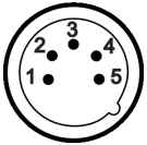 |
1 – Shield 2 – Signal (-) 3 – Signal (+) 4 – Not connected 5 – Not connected |
 |
1 – Shield 2 – Signal (-) 3 – Signal (+) 4 – Not connected 5 – Not connected |
If you are using the standard DMX controllers, you can connect the DMX output of the controller directly with the DMX input of the first fixture in the DMX chain. If you wish to connect DMX controllers with other XLR outputs, you need to use adaptor cables.
Building a serial DMX chain
Connect the DMX output of the first fixture in the DMX chain with the DMX input of the next fixture. Always connect one output with the input of the next fixture until all fixtures are connected. Up to 32 fixtures can be conected.
Caution: At the last fixture, the DMX cable has to be terminated with a terminator. Solder a 120 Ω resistor between Signal (–) and Signal (+) into a 3-pin XLR-plug and plug it in the DMX output of the last fixture.

4.5 Ethernet connection
The fixtures on a data link are connected to the Ethernet with ArtNet communication protocol.The control software running on your PC (or light console) has to support Art-Net protocol.
Art-Net communication protocol is a 10 Base T Ethernet protocol based on the TCP/IP.Its purpose is to allow transfer of large amounts of DMX 512 data over a wide area using standard network technology.
IP address is the Internet protocol address.The IP uniquely identifies any node (fixture) on a network.
The Universe is a single DMX 512 frame of 512 channels.
The Robin T15 is equipped with 8-pin RJ- 45 sockets for Ethernet connection.Use a network cable category 5 (with four “twisted” wire pairs) and standard RJ-45 plugs in order to connect the fixture to the network.
RJ-45 socket (front view): 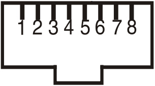 |
1- TD+ 2- TD- 3- RX+ 4- Not connected |
5- Not connected 6- RX 7- Not connected 8- Not connected |
RJ-45 plug (front view):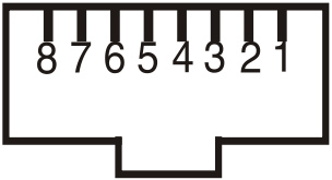 |
Patch cables that connect fixtures to the hubs or LAN sockets are wired 1:1,that is,pins with the same numbers are connected together:
| 1-1 | 2-2 | 3-3 | 4-4 | 5-5 | 6-6 | 7-7 | 8-8 |
If only the fixture and the computer are to be interconnected,no hubs or other active components are needed.A cross-cable has to be used:
| 1-3 | 2-6 | 3-1 | 4-8 | 5-7 | 6-2 | 7-5 | 8-4 |
Connect the Ethernet inputs of all fixtures with the Ethernet network.
Option “ Artnet” (gMaI or gMA2 or sACN) has to be selected from “Ethernet Mode” menu at each fixture.
Set IP address (002.xxx.xxx.xxx / 010.xxx.xxx.xxx) and the Universe at each fixture.
Example:

An advised PC setting: IP address: 002.xxx.xxx.xxx (Different from fixture IP addresses)
NET mask: 255.0.0.0
The EP version of the fixture is equipped with two RJ 45 sockets and Ethernet Pass Through Switch which sustains Ethernet integrity, when the fixture has no power, it automatically maintains network connectivity. If you use the Ethernet IN-OUT way for the Ethernet connection, max. 8 fixtures can be connected in the IN-OUT line.
4.6 Wireless DMX operation
The external ROBE Wireless DMX/RDM module allows receiving wireless DMX. The ROBE wireless DMX/RDM module has full support for wireless communication protocols at entertainment market. Modul is based on well known LumenRadio RF technology, with implemented wire interface for connection with Robe products. RF output for MCX interface antenna as standard output.

Push in the 5-pin XLR plug (1) into 5-pin XLR sockit (4) and simultaneously locating pin (2) into hole (5) in the fixture. In this way the wireless DMX module is connected with the fixture.
NOTE: when you disconnect the DMX wireless module from fixture, press and hold lock (5) during getting the wireless module out.
To link the fixture with DMX transmitter.
The fixture can be only linked with the transmitter by running the link procedure at DMX transmitter .
After linking , the level of DMX signal ( 0-100 %) is displayed in the menu item “Stat“ (Special –>Vireless –>Stat).
To unlink the fixture from DMX transmitter.
The fixture can be unlinked from transmitter via the menu item “ Unlink“ (Special–>Vireless –>Unlink.).
Remotely controllable functions
5.1 Colour influencing functions
Factory setting of menu functions (channels) which influence behaviour of colour channels is the following:
| Function | Factory setting | Function | Factory setting |
| DMX mode | 1 | Uniformity | Off |
| White Point | On | Colour mix control | 0 DMX |
| Colour mixing mode | CMY | CCT | 110 DMX (5600K) |
| Dimmer curve | Square law | CRI Selection | Low (0 DMX) |
| Tungsten effect simulation | Off | Green correction | Uncorrected (128 DMX) |
| Chromatic white | Off | Shutter/Strobe | Open (32 DMX) |
| Light output stability | Off | Dimmer | Closed (0 DMX) |
White Point (menu “Pers–>White P.”)
The function switches on/off an internal control of colours. For a standard operation of the fixture the option should be switched to ON. Option OFF has to be set during colour calibration of the fixture (in this mode some functions e.g. Tungsten effect, Virtual colour wheel are disabled).
Colour mixing system (menu “Pers–>Col. Mix”, DMX channel “Colour functions”)
This item allows selection between RGB and CMY mode. In 3-colour controlling modes (Mode 1,Mode 2, Mode 6, Mode 7) all internal 5 colours are always utilized where possible.
Dimmer curve (menu “Pers–>Dimmer C”. DMX channel “Colour functions”)
The fixture allows you to select a linear dimmer curve or a square law curve.
Tungsten effect simulation (menu “Pers–>Tungsten”, DMX channel “Colour functions”)
The function simulates behaviour of a halogen lamp during dimming at calibrated white colours 2700K – 4200K.
You can select from various lamp wattage simulation: 750W, 1000W, 1200W, 2000W, 2500W.
If the function Chromatic white is on, the Tungsten effect will influence also mixed colours.
Saving user colours (DMX channel “Colour functions”)
To save user colours:
- Set the function White Point to off (Channel Colour Mix Control, range 70-79 DMX).
1.Mix desired colour on colour channels. - Stay in desired position of user colours (216-235 DMX) on the Virtual colour wheel for 1 sec.
- Leave the range of user colours (216-235 DMX) on the Virtual colour wheel.
- Repeat steps 2-4 for next user colour.
- To permanently save user colours, stay for 3 sec. at DMX range of 110-114 on the channel Colour functions.
After that the colour system will be reset (this action can last about 2 minutes). Previous user colours will be overwritten.
Chromatic white (menu “Pers–>Chro. W.”, DMX channel “Colour functions”)
If the function is on, the CCT channel influences calibrated white colours and mixed colours (also colours on Virtual colour wheel).
If the function is off, the CCT channel influences calibrated whites only.
Light output stability (menu “Pers–>Li O.S.”, DMX channel “Colour functions”)
If the function is on, the light output from the fixture is immediately reduced to a value corresponding to a thermal drop of the light intensity from the LED engine (the thermal drop of light intensity – decreasing of the light intensity on circa 90 % of starting level after first 5 minutes, then is the thermal drop of light intensity inconsiderable).
Output Uniformity (menu “Pers–>O. Uni.”, DMX channel “Colour functions”)
If the function is on, the light intensity from the fixture is corrected in order to get approximately the same light intensity as from another fixture which has also the function on. Thanks to the function, light outputs from more fixtures will have approximately the same light intensity.
Colour Mix control (DMX channel “Colour Mix control”)
The Colour Mix control channel defines relation between colour channels (Cyan, Magenta, Yellow, Red, Green, Blue, Amber, Lime and CCT ) and the colours on the virtual colour wheel:
| DMX value | Function |
| 0 – 9 | Virtual colour wheel has priority over colour channels (default setting) |
| 10-19 | Maximum mode (highest values have priority) |
| 20-29 | Minimum mode (lowest values have priority) |
| 30-39 | Multiply mode (multiply virtual colour wheel and colour channels) |
| 40-49 | Addition mode (virtual colour wheel + colour channels) |
| 50-59 | Subtraction mode (virtual colour wheel – colour channels) |
| 60-69 | Inverted Subtraction mode (virtual colour wheel – colour channels) |
| 70-79 | White Point Off (CCT+green correction+virtual col. wheel deactivated) |
| 80-128 | Reserved |
| 129 | Crossfade Virtual colour wheel only |
| 130-254 | Crossfade between virtual colour wheel and colour channels |
| 255 | Crossfade colour channels only |
CTO (DMX channel ” CTO “)
The CTO channel allows you to change a colour temperature of calibrated white colours in range of 8000K-2700K and also can influence mixed colours including colours on the Virtual colour wheel.
For correct function of the CCT channel on calibrated white colours, the following conditions have to be kept:
- The Colour calibration mode has to be set on (menu “Pers–>White P. –>On”).
If the Chromatic white is set off, the CTO channel influences white colours only.
If the Chromatic white is set on, the CTO channel influences white colours and mixed colours including colours on the Virtual colour wheel. - The following channels have to be set at:
Virtual colour wheel at 0 DMX
Green correction at 128 DMX
Colour mix control channel at 0 DMX - Colour channels have to be set depending on the colour mixing mode and the DMX mode.
CMY colour mixing mode.
DMX mode 1:
Channels Cyan/Red, Magenta/Green and Yellow/Blue (both 8-bit and 16-bit channels for each colour) have to be set at 0 DMX or at the same DMX value (except 255 DMX).
DMX mode 2
Channels Cyan/Red, Magenta/Green and Yellow/Blue have to be set at 0 DMX or at the same DMX value (except 255 DMX) .
DMX mode 3:
The mode is not intended for CMY colour mixing mode.
RGB(A,L) colour mixing mode
DMX mode 1:
Channels Cyan/Red, Magenta/Green and Yellow/Blue (both 8-bit and 16-bit channels for each colour) have to be set at 255 DMX or at the same DMX value (except 0 DMX).
DMX mode 2:
Channels Cyan/Red, Magenta/Green and Yellow/Blue have to be set at 255 DMX or at the same DMX value (except 0 DMX).
DMX mode 3:
Channels Red, Green, Blue, Amber and Lime (both 8-bit and 16-bit channels for each colour) have to be set at 255 DMX or at the same DMX value (except 0 DMX). - Shutter and dimmer have to be open.
CRI correction (DMX channel ” CRI Selection”)
The channel allows you to set CRI from Low (80) to High (90+). Default setting is 0 DMX (Low CRI).
Green correction (DMX channel “Green correction “)
The channel allows you a fine correction of colours (whites, mixed colours, colours on the Virtual colour wheel).
E.g. white colour from red to green tint.
Virtual colour wheel (DMX channel ” Virtual colour wheel”)
The virtual colour contains 67 preset colours and 10 user colours.
Dimmer/Shutter (DMX channels ” Shutter/Strobe” and “Dimmer Intensity”)
Smooth 0 – 100 % dimming is provided by the electronic control unit of the light source. The control of the light source also allows strobe effects with variable speed.
5.2 Motorized effect functions
Zoom
Motorized zoom in range of 10° – 72° for both (Fresnel and PC) lenses.
| Level 1 | Level 2 | Level 3 | Level 4 | Level 5 | Level 6 | Level 7 |
| DMXA | Set DMXA | 001-512 | ||||
| DMX Pres. | Mode 1 | |||||
| : | ||||||
| Mode 6 | ||||||
| IP Addr | Def addr | |||||
| Cus addr | IP 1 | 0-255 | ||||
| IP 2 | 0-255 | |||||
| IP 3 | 0-255 | |||||
| IP 4 | 0-255 | |||||
| Set Address | ||||||
| NEt Mask | N.M. 1 | 0-255 | ||||
| N.M. 2 | 0-255 | |||||
| N.M. 3 | 0-255 | |||||
| N.M. 4 | 0-255 | |||||
| Set Net M. | ||||||
| Gateway | Gw.1 | 0-255 | ||||
| Gw.2 | 0-255 | |||||
| Gw.3 | 0-255 | |||||
| Gw.4 | 0-255 | |||||
| Set GateW. | ||||||
| Info | PO Time | Total | ||||
| Reset | ||||||
| L OTi | R LOT | |||||
| G LOT | ||||||
| B LOT | ||||||
| A LOT | ||||||
| L LOT | ||||||
| DMX Val | Powr | |||||
| : | ||||||
| Dimm F | ||||||
| Temps | Base Tmp | Current | ||||
| Highest | ||||||
| High Res | ||||||
| LB1 Tmp | Current | |||||
| Highest | ||||||
| High Res | ||||||
| LB2 Tmp | Current | |||||
| Highest | ||||||
| High Res | ||||||
| LEDs Tmp | Current | |||||
| Highest | ||||||
| High Res | ||||||
| IP Addr | IP A. 1 | |||||
| IP A. 2 | ||||||
| IP A. 3 | ||||||
| IP A. 4 | ||||||
| MAC Addr | MAC A. 1 | |||||
| : | ||||||
| MAC A. 6 | ||||||
| RDM UID | RDM U. 1 | |||||
| : | ||||||
| RDM U. 6 |
| Level 1 | Level 2 | Level 3 | Level 4 | Level 5 | Level 6 | Level 7 |
| Sw Ver | IC-DE | |||||
| IC-L1 | ||||||
| IC-L2 | ||||||
| IC-L3 | ||||||
| IC-O | ||||||
| IC- DL | ||||||
| IC-POT | ||||||
| IC-6 | ||||||
| Pers | DMX Pres | Mode 3 | ||||
| : | ||||||
| Mode 8 | ||||||
| DMX In | Wired | |||||
| Ethernet | ||||||
| Ethernet | Eth Mode | ArtNet | ||||
| sACN | ||||||
| gMA I | ||||||
| gMA II | ||||||
| ArtNet | Uni | 0-255 | ||||
| sACN | Uni | 1-63999 | ||||
| MANet | Uni | 1-256 | ||||
| sID | 1-32 | |||||
| IGMP r | Off | |||||
| 1-10s | ||||||
| Eth Back | Off, On | |||||
| Display | Turn | |||||
| On/Off T | On, Off | |||||
| Contrast | 0-100% | |||||
| Backlight | 0-100% | |||||
| Mic Sens. | 1-11-20 | |||||
| Fans | Fans Mode | Auto | ||||
| Quiet | ||||||
| BLC Fans | On, Off | |||||
| Noise L. | 0%-100% | |||||
| Tungsten | Off | |||||
| 750W | ||||||
| 1000W | ||||||
| 1200W | ||||||
| 2000W | ||||||
| 2500W | ||||||
| Col Mix | RGB | |||||
| CMY | ||||||
| White P. | On. Off | |||||
| Dimmer C | Sqrl | |||||
| SuSql | ||||||
| Line | ||||||
| Opt Br | On, Off | |||||
| Li. O.s.. | Off, On | |||||
| Chro. W. | On, Off | |||||
| O. Uni | On, Off | |||||
| LED Freq. | 300 | |||||
| 600 | ||||||
| 1200 | ||||||
| 2400 | ||||||
| High | ||||||
| LED F.adj | ….-126-1, 0, 1…126 |
| Level 1 | Level 2 | Level 3 | Level 4 | Level 5 | Level 6 | Level 7 |
| Temp Uni | °C, °F | |||||
| I Ef Pos | Powr | |||||
| : | ||||||
| Dimm F | ||||||
| Store | ||||||
| User Col | View Col. | U col 1 | ||||
| : | ||||||
| U col 10 | ||||||
| Dist. Col | ||||||
| Res Wpas | ||||||
| Defaults | ||||||
| Manual | Powr | 0-255 | ||||
| : | ||||||
| Dimm F | 0-255 | |||||
| Test Prg | ||||||
| St Alone | Music T | On, Off | ||||
| Auto Run | Off | |||||
| Test | ||||||
| Prog 1 | ||||||
| Prog 2 | ||||||
| Prog 3 | ||||||
| Pr Play | Test Prg | |||||
| Prog 1 | ||||||
| Prog 2 | ||||||
| Prog 3 | ||||||
| Pr Edit | Prog 1 | Step 1 | Powr | |||
| Prog 2 | : | : | ||||
| Prog 3 | Step 40 | F.Tim | 0-25.5 | |||
| S.Tim | 0-25.5 | |||||
| COPY | ||||||
| Prg En | 1-40 | |||||
| Reset | ||||||
| Special | RDM Low | |||||
| RDM Hight | ||||||
| Adjust | DMX Val | Powr | 0-255 | |||
| : | ||||||
| Dimm F | 0-255 | |||||
| Calib | Cal Mech | Zoom C | 0-255 | |||
| Store | ||||||
| Cal. Col. | Red C. | R X,R Y, R I,R T | ||||
| Gre C. | G X,G Y, G I,G T | |||||
| Blu C. | B X,B Y, B I,B T | |||||
| Amb C. | A X,A Y, A I,A T | |||||
| LiG C. | L X,L Y, L I,L T | |||||
| Green Corr | 2700K I-8000K I | 100-155 | ||||
| 2700K C-8000K C | 100-155 | |||||
| Store | ||||||
| LEDs Cur | ||||||
| Cal Load | No, Yes | |||||
| Sw Upd | No, Yes |
The Robin T15 is equipped with the two-row LCD display & 4 control buttons which allow you to set fixture´s behaviour according to your needs, obtain information on its operation, control all range of effects and program it in the stand-alone mode. The four control knobs have functions according function modes.
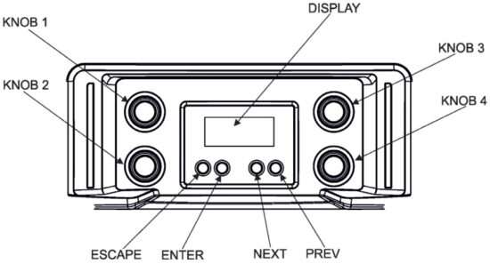
Control buttons on the front panel:
ESCAPE button used to leave the menu without saving changes.
NEXT and PREV buttons for moving between menu items and symbols, adjusting values.
ENTER button used to enter the selected menu item and to confirm adjusted value.
Sliders
Two sliders on the side of the fixture alows you precise control of functions mapped on them.
Default mapping is the following:
Slider 1-Zoom
Slider 2-Intensity
Sliders can be used in the Simple mode only.

7.1 Simple mode
In the Simple mode, the fixture is controlled by means of four control knobs and the fixture´s effects cannot be controlled by DMX.
To enter the Simple mode, press any control knob for two seconds and the first page of the Simple mode will be displayed on the screen with controllable items next to corresponding knobs. After pressing desired knob, its current blinking value will be displayed and can be changed by the knob. Adjusted value can be saved by pressing the knob.
To switch to the second page, press the NEXT button. To return back, press the PREV button.
Control pages overview:

INT (Light Intensity), values: 0%-99%, MAX
Default = MAX
+- G (Green correction), values: -99 – +99 Default=0
CCT (Correlated Color Temperature), values: 2700-8000 K
Default=2700
ZOM (Zoom), values: MAX, 99%,98%..00%
Default=MAX

CYA (Cyan), values: 00%-99%, MAX
Default=00%
YEL (Yellow), values:00%-99%, MAX
Default =0%
MAG (Magenta), values: 00%-99%, MAX
Default =0%
VCW (Virtual Colour Wheel), values: NOF, 4, 10, 19…793
Default=NOF (no function). VCW takes priority over CMY colours

CRI (Colour Rendering Index),
values: MIN, OPT, MAX
Default=MIN
BCL (Button backlight),
values: OFF, ON
Default=OFF
FAN (Fans Operating Mode), values: AUTO,1%-99%, MAX
Default=AUTO
To set values on pages stated above to the default (factory) values, press and hold any two knobs simultaneously for two seconds. During the action you have to be in the Simple mode.
To leave the Simple mode, press any control knob for two seconds or press the ESCAPE button or send DMX command (130-134 DMX) on the channel Power/Special functions.
After leaving the Simple mode, the fixture´s effects can be controlled by DMX. If you enter the Simple mode again, values saved in last Simple mode will be recalled.
If the fixture in the Simple mode is switched off and on again, it will remain in the Simple mode.
By pressing any two knobs for two seconds at the same time (T15 has to be in the standard display menu, not in the Simple mode) you will open a light output and the sign “Fast On” will be displayed. To close the light output, press any two knobs at the same time for two seconds. This function is useful for fast switching the light output on during adjusting the fixture on a truss.
7.3 Standard mode
The following menu items are accessible in the standard mode only.
7.3.1 DMXA (DMX and Ethernet Address)
Set DMXA – Use this menu item to set the DMX start address of the fixture, which is defined as the first channel from which the ROBIN T15 will respond to the controller.
If you set, for example, the address 20, the ROBIN T15 will use channels 20 – 39 for control (if Mode 1 is selected).
Please, be sure that you do not have any overlapping channels in order to control each ROBIN T15 correctly and independently from any other fixture on the DMX data link.
Blinking DMX address means that the fixture is either not receiving DMX data or that the set DMX address is higher then allowed, exceeding the DMX footprint of the set DMX mode.
DMX Pres. – DMX preset. Use the menu to select desired channel mode.
Mode 1 – 20 control channels
Mode 2 – 10 control channels
Mode 3 – 24 control channels
Mode 4 – 7 control channels
Mode 5 – 2 control channels
Mode 6 – 1 control channel
IP Addr. – IP address. Select this menu to set IP address. IP address is the Internet protocol address.The IP address uniquely identifies any node (fixture) on a network.
There cannot be 2 fixtures with the same IP address on the network!
Def. addr. – Default IP address.
Cus. addr. – Custom IP address. You can set up IP address according your needs. The address you can set by each octet (IP1. IP2, IP3, IP4). Confirm by “Set Address”
Net Mask – Network Mask. The option enables to set up all bytes of Net Mask by each octet (N.M.1, N.M.2, N.M.3, N.M.4). Confirm by “Set Net M.”
Gateway – Gateway setting. The option enables to set up all bytes of Gateway by each octet (GW. 1, GW.2, GW.3, GW.4). Confirm by “Set GateW.”
7.3.2 Info (Fixture information)
PO Time – Power on time. Select the menu to read the number of fixture operation hours.
Total – The item shows the total number of the operation hours since the ROBIN T15 has been fabricated.
Reset – The item shows the number of the operation hours since the counter was last reset.
In order to reset this counter to 0, press and hold both [NEXT] and [PREV] buttons and the [Enter] button at the same time.
LOTi – LEDs on time. Select the menu item to read the number of operation hours of individual LEDs.
R LOT. – Red LEDs on time.
G LOT. – Green LEDs on time.
B LOT. – Blue LEDs on time.
A LOT. – Amber LEDs on time.
L LOT. – Lime LEDs on time.
DMX Val. – DMX values. The menu allows you to read DMX values of each channel received by the fixture.
Temps – Fixture temperatures. The menu shows temperatures in the fixture.
LEDsTmp. – The menu shows temperature on the LED PCB in the light source
Current – The current temperature of the LED PCB.
Highest – The highest temperature of the LED PCB since the fixture has been fabricated.
High Res. – The highest temperature of the LED PCB since the counter was last reset.
In order to reset this counter to 0, press and hold both [NEXT] and [PREV] buttons and the [Enter] button at the same time.
LB1 Tmp. – The menu shows temperature on the LEDs control PCB (RB 3406-top side) in the fixture.
Current – The current temperature on the LEDs control PCB.
Highest – The highest temperature on the LEDs control PCB since the fixture has been fabricated.
High Res. – The highest temperature on the LEDs control PCB since the counter was last reset.
In order to reset this counter to 0, press and hold both [NEXT] and [PREV] buttons and the [Enter] button at the same time.
LB2 Tmp. – The menu shows temperature on the LEDs control PCB (RB 3406-bottom side) in the fixture.
Current – The current temperature on the LEDs control PCB.
Highest – The highest temperature on the LEDs control PCB since the fixture has been fabricated.
High Res. – The highest temperature on the LEDs control PCB since the counter was last reset.
In order to reset this counter to 0, press and hold both [NEXT] and [PREV] buttons and the [Enter] button at the same time.
Base Tmp. – The menu shows temperature on the display PCB in the fixture.
Current – The current temperature on the display PCB.
Highest – The highest temperature on the display PCB since the fixture has been fabricated.
Highest Res. – The highest temperature on the display PCB since the counter was last reset.
In order to reset this counter to 0, press and hold both [NEXT] and [PREV] buttons and the [Enter] button at the same time.
IP Addr. – IP address.The menu allows you to read the IP address of the fixture.
MAC Addr. – MAC address.The menu allows you to read the MAC address of the fixture.
RDM UID. – RDM UID.The menu allows you to read RDM UID of the fixture.
Sw. Ver, – Software versions. Select this item to read the software version of fixture modules.
IC-D – A display processor.
IC-DE – An EEprom.
IC-L1 – LEDs control processor 1.
IC-L2 – LEDs control processor 2.
IC-L3 – LEDs control processor 3.
IC-O – Zoom control processor.
IC-POT – Faders control processor.
7.3.3 Pers(Personality)
DMX Pres – DMX preset. Use the menu to select desired channel mode.
Mode 1 – 20 control channels
Mode 2 – 10 control channels
Mode 3 – 24 control channels
Mode 4 – 7 control channels
Mode 5 – 2 control channels
Mode 6 – 1 control channel
DMX In- DMX input. Use the menu to select mode of DMX signal receiving.
Wired – DMX signal is received by means of the standard DMX cable.
Ethernet – DMX signal is received by means of ETHERNET cable.
Ethernet – Ethernet operation. The menu allows you to set fixture for Ethernet operation.
Eth Mode – The menu item allows you to select desired protocol:
ArtNet
sACN
gMA I
gMA II
ArtNet – Use the menu item to select desired universe for ArtNet (Uni), range 0-255
sACN – Use the menu item to select desired universe for sACN (Uni), range 1-63999
MANet – Use the menu item to select desired universe (Uni) for MANet, range 0-256 and ID session (sID), range 1-32.
IGMP – Use the menu item to set time for connecting to multitask address (1-10sec.) for IGMP protocol.
Eth Back – Ethernet Back-up. If the function is On, the fixture automatically switches to the Ethernet input for signal receiving in case of DMX signal loss. Correct protocol has to be set in the menu ” Eth Mode” and the option Wired or Wireless* has to be set in the menu “DMX In”.
* If Wireless DMX module is installed.
Display – Display adjusting. This menu allows you to adjust the display behaviour.
Turn – This function turns the display by 180°.
On/Off T – This function allows you to keep the display permanent on or turn it off two minutes after last pressing any button on the control panel.
Contrast- Use this function to adjust contrast of the display (0-100%).
Backlight- Use this function to adjust backlight of the display (0-100%).
Mic. Sens. – Microphone Sensitivity. Enter the menu if you want to adjust the microphone sensitivity from 1 (max.) to 20 (min.).
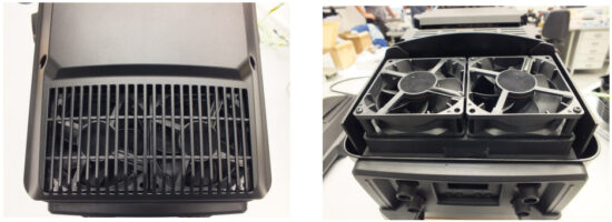
Fans – Fans setting. Use the menu to set behaviour of fixture fans.
FansMode – the menu allows you to select desired power of fans:
Auto – Auto-control mode
Quiet – If the options is selected, power of fans can be set in the menu “Noise L.”
BLC Fans – The menu item allows you to stop all fans in the fixture (option “On”) when its light output is closed (shutter in range of 0-31 DMX or dimmer in 0 DMX).
Noise L. – The menu item allows you to set speed of fans. At low speed of fans the light output may be reduced.
Tungsten – Tungsten effect. This function simulates behaviour of a halogen lamp during dimming at calibrated whites 2700K-4200K. You can select from various lamp wattage simulation:
750W
1000W
1200W
2000W
2500W
Col. Mix – Colour mixing mode. This menu item allows selection between RGB and CMY mode. In 3-colour controlling modes (Mode 1, Mode 2, ) all internal 5 colours are always utilized where possible.
White P. – White Point. The function switches on/off an internal control of colours. For a standard operation of the fixture the option should be switched on. Option off has to be set during colour calibration of the fixture.
Dimmer C – Dimmer curve. Use the menu to select desired dimmer curve.
Line – a linear curve.
Sqrl – a square law curve.
SuSql – a super square law curve.
Opt Br. – Optic Brake – If the function is switched to the option On, the zoom will be blocked and will not respond to DMX values. After switching the fixture off and on, the zoom will stay in the original positions (position at moment of activation the brake).
Li. O S – Light output stability. If the function is on, the light output from the fixture is immediately reduced to a value corresponding to a thermal drop of the light intensity from the LED engine (the thermal drop – decreasing of the light intensity on 90 % of a starting level after first 5 minutes, then is the thermal drop inconsiderable).
Chro. W. – Chromatic White. If this function is on, the CCT channel influences colours and calibrated white colours. If this function is off, the CTO channel influences calibrated whites only.
O. Uni. – Light output uniformity. If the function is on, the light intensity from the fixture is corrected in order to get approximately the same light intensity as from another fixture which has also the function on. Thanks to the function, light outputs from more fixtures will have approximately the same light intensity.
LED Freq – LEDs frequency setup. The function allows you to set the PWM (Pulse Width Modulation) output frequency of LEDs. You can select from the following values:
300 Hz
600 Hz
1200 Hz
2400 Hz
High
LED F.adj – LEDs frequency fine adjustment. The function allows you to change the selected PWM output frequency of LEDs in 1266 levels up and down around the selected frequency in the menu “LED Freq”.
-126…-001 – Frequence levels 1-126 under selected frequency.
000 – Selected frequency
001…126 – Frequence levels 1-126 above selected frequency.
Temp Uni – Temperature unit. Use the menu item to change temperature unit from °C to °F.
I Ef Pos – Init effect positions. Use the menu to set all effects to the desired positions at which they will stay after switching the fixture on without DMX signal. Confirm setting by the item “Store”.
Reset WPas. – Rest Web password. The menu item allows you to reset a password for access to the REAP (default password: 2479, user: robe).
Defaults – The menu item allows to set all fixture parameters to the default (factory) values.
7.3.4 Manual Control (Manual)
Use the menu to control all fixture channels by means of control buttons.
7.3.5 Test program (Test Prg)
Use this menu to to run a special demo-test sequences without an external controller, which will show you some possibilities of using ROBIN T15.
7.3.6 Stand-alone (St Alone)
Auto Run – Presetting playback. This function allows you to select the program which will be played in the stand-alone mode after switching the fixture on. Selected program will be played continuously in a loop.
Off – The option disables „Auto Run” function.
Test – The option will start built-in test program.
Prog 1 – The option will start user-created program 1
Prog 2 – The option will start user-created program 2
Prog 3 – The option will start user-created program 3
Pr Play – Playing program. Select this menu to run a user-created program in a loop.
Test Prg – The option runs built-in test program.
Prog 1 – The option runs user-created program 1
Prog 2 – The option runs user-created program 2
Prog 3 – The option runs user-created program 3
Select the program you wish and press [ENTER]. The selected program starts running. By Pressing [ENTER] again, program pauses its running.
Pr Edit – Editing program. Select this menu to edit or create the program. The ROBIN T15 has one built-in program and one user-editable program up to 40 steps. Each program step has a step time – during which effects last in the current step and a fade time- during which effects move to new positions.
To edit program:
Procedure:
- Press [NEXT] or [PREV] to select the menu “Edit” and press [ENTER].
- Press [NEXT] or [PREV] to select the desired program step and press [ENTER] button.
- Press [NEXT] or [PREV] to select the desired item and press [ENTER] button. Now you can edit by [NEXT] or [PREV] buttons the DMX value (0-255) for selected item:
Prg En. a total number of the program steps (value 1-40). This value you should be set before starting of programming (e.g. if you want to create program with the 10 steps, set Prg En=10). Powr power/special functions L Fre a LEd frequency selection L Fr S a LEd frequency fine adjusting Col F colour functions CRI S a CRI selection Virt C a virtual colour wheel Red a red colour coarse Red F a red colour fine Green a green colour coarse Green F a green colour fine Blue a blue colour coarse Blue F a blue colour fine Amb an amber colour Amb F an amber colour fine L Gre a lime green L Gre F a lime green fine CTC a colour temperature correction Gre C a green correction C Mix C a colour mix control Zoom a zoom coarse Zoom F a zoom fine Stro a strobe/shutter function Dimm a dimmer function coarse Dim F a dimmer function fine F.Tim a fade time (0-25.5 sec) S.Tim a step time (0-25.5 sec) COPY copy the current prog. step to the next prog. step - Press [ENTER] button to confirm adjusted value .
- Press [ESCAPE] button, select next prog. step, press [ENTER] button and repeat steps 3 – 5).
7.3.7 Reset
This option enables you to reset mechanical zoom of the fixture.
7.3.8 Special functions (Special)
RDM Low – This menu item shows the first part of the RDM identification code.
RDM High – This menu item shows the second part of the RDM identification code.
Wireless – Wireless DMX information. The menu allows you to read some information about Wireless DMX operation (if wireless DMX/RDM module is connected)
Stat – Wireless status. Use the menu to read wireless DMX status.
Unlink – use the item to unlink the fixture from wireless DMX transmitter .
Adjust – Adjustment. The menu allows the fine adjustment of effects.
DMX Val- DMX values. Use the menu to set DMX values of fixture´s channels.
Calib – calibration of the fixture.
Cal Mech – Use this menu to calibrate mechanical parts the fixture.
Zoom C. – Use the menu item for fine calibration of a zoom position.
Calibration of the zoom the control board
- Disconnect DMX controller from the fixture and enter the “Cal Mech” menu.
- Use the [PREV] and [NEXT] to find “Zoom C” and press [ENTER].
- Set desired value and save it by pressing [ENTER].
- After calibrating zooms, find item “Store” and press [ENTER]. to save adjusted value.
Calibration protocol:
| Effect | Mode 1 | Mode 2 | Mode 3 | Mode 4 | Mode 5 |
| Zoom | channel 21 | channel 11 | channel 25 | channel 8 | channel 3 |
Cal Col – The menu items “Red C”, “Gre C”, “Blu C”, “Amb C” and “LiG C” serve for calibration of colours in the factory. User should not change settings in this menu.
The menu “Green Corr” serves for calibration of whites at standard CRI (2700K I, 3200K I, 4200K I,5600K I, 8000K I) or high CRI (2700K C,3200K C,4200K C, 5600K C, 8000K C).
LEDs Cur – Calibration of LED currents. This process waits about 5 minutes and after its finishing the sign “CurC DONE” will apear on the display.
Cal Load – Loads default (factory) calibration.
Sw Upd – Software update. The menu item allows you to update software in the fixture via either serial or USB port of PC.
The following items are required in order to update software:
– PC running Windows or Linux or macOS
– DSU file
– Flash cable RS232/DMX, P/N13050624 (if you want to use a serial port of PC)
– Robe Universal Interface or Robe Universal interface WTX (if you want to use an USB port of PC)
After the software updating the fixture will be set to default values.
To update software in the fixture:
- DSU file is available from Robe web site at WWW.robe.cz.
File with extension zip is intended for Windows (used and tested from XP to W10 on 32/64bit systems).
File with extension tbz is intended for Linux (used and tested on Debian and Ubuntu 32/64bit).
File with extension dmg is intended for macOS (used and tested on OSX up to Sierra) XQuartz required, install it from https://www.xquartz.org/
Save the download file to a folder on your computer.
In case that you use windows, extract files in the zip file (e.g. DSU_RobinT15_18100828.zip) - Disconnect the fixture from DMX controller.
- If you use the flash cable RS232/DMX, connect a serial port of your computer with DMX input of the fixture by means of the cable.
If you use the Robe Universal Interface, connect a USB port of your computer with the Robe Universal Interface by means of the USB cable and DMX input of the fixture with the DMX output of the Robe Universal Interface via a DMX cable. - Switch the fixture to the update mode (tab “Service” –> Update Software).
Note: If you do not want to continue in the software update, you have to switch off and on the fixture to escape from the updating mode.
We recommend to cancel all running programs on your computer before starting the software update. - Double-click the software uploader file (e.g. DSU_RobinT15_18100828.exe) in
the extracted files. The Software Uploader program will start to run.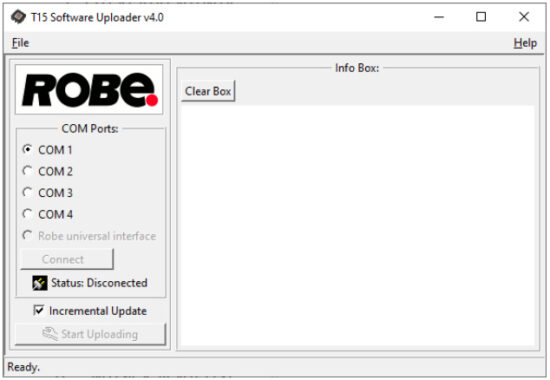
- Select correct “COM ” number if you use a Flash cable RS232/DMX or select “Robe Universal Interface ” if you use the Robe Universal Interface/Robe Universal Interface WTX and then click on the “Connect” button.
- If the connection is OK, click the “Start Uploading” button to start software uploading. It will take several minutes to perform software update.
If the option “Incremental Update” is not checked, all processors will be updated (including processors with the same software version).
If you wish to update only processors with new version of software, check the “Incremental Update box“.
Avoid interrupting the process. Update status is being displayed in the “Info Box” window.
When the update is finished, the line with the text “Fixture is successfully updated“ will appear in this window.
In case upload process is interrupted (e.g. power loss), the fixture stays in “Updating mode” and you will have to repeat the software update again.
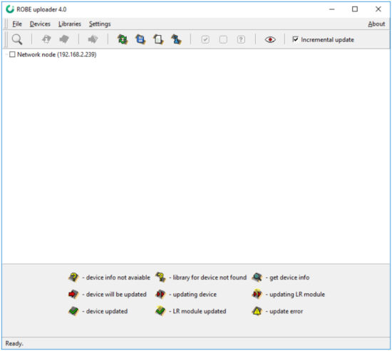
Another way, how to update software in the fixtures (especially large installation of fixtures) is to use the ROBE Uploader. It is a software for automatized software update of Robe fixtures. It takes advantage of RDM support).
For more information please see https://www.robe.cz/robe-uploader/.
RDM
This fixture supports RDM operation. RDM (Remote Device Management) is a bi-directional communications protocol for use in DMX512 control systems, it is the new open standard for DMX512 device configuration and status monitoring.
The RDM protocol allows data packets to be inserted into a DMX512 data stream without adversely affecting existing non-RDM equipment. By using a special „Start Code,“ and by complying with the timing specifications for DMX512, the RDM protocol allows a console or dedicated RDM controller to send commands to and receive messages from specific moving lights.
RDM allows explicit commands to be sent to a device and responses to be received from it.
The list of commands for Robin T15 is the following.
| Parameter ID | Discovery command | SET command | GET command |
| DISC_UNIQUE_BRANCH | * | ||
| DISC_MUTE | * | ||
| DISC_UN_MUTE | * | ||
| DEVICE_INFO | * | ||
| SUPPORTED_PARAMETERS | * | ||
| SOFTWARE_VERSION_LABEL | * | ||
| DMX_START_ADDRESS | * | * | |
| IDENTIFY_DEVICE | * | * | |
| DEVICE_MODEL_DESCRIPTION | * | ||
| MANUFACTURER_LABEL | * | ||
| DEVICE_LABEL | * | * | |
| SENSOR_DEFINITION | * | ||
| SENSOR_VALUE | * | ||
| DISPLAY_INVERT | * | * | |
| DISPLAY_LEVEL | * | * | |
| DEVICE_RESET | * | ||
| DMX_PERSONALITY | * | * | |
| DMX_PERSONALITY_DESCRIPTION | * | ||
| STATUS_MESSAGES | * | ||
| STATUS_ID_DESCRIPTION | * |
RDM model ID for the Robin T15 is 0x0141.
Robe Ethernet Access Portal (REAP)
The REAP allows you to display on your computer information about some fixture settings, operating conditions (e.g. temperature in the fixture) and error messages which were generated during fixture operation.
Your computer needs to be connected to the fixture(s) through the means of Ethernet wired network and a network switch.
The Ethernet network connection (Local LAN) typically needs to be set to 2.x.x.x address, assuming that no other computer on the network contains such an address while keeping all ROBE fixtures in default IP settings.
For more information about REAP options, computer and fixture settings please see the REAP user manual at https://www.robe.cz/res/downloads/user_manuals/User_manual_REAP.pdf.
Error and information messages
Zoom Err
This message will appear after reset of the fixture if the zoom module is not located in the default position.
Cause of the message can be some defective zoom stepping motor.
Red Shrt
The message informs you that short circuit has occurred in the red LEDs circuit on the LEDs PCB.
Green Shrt
The message informs you that short circuit has occurred in the green LEDs circuit on the LEDs PCB.
Blue Shrt
The message informs you that short circuit has occurred in the blue LEDs circuit on the LEDs PCB.
Amber Shrt
The message informs you that short circuit has occurred in the amber LEDs circuit on the LEDs PCB.
Lime Shrt
The message informs you that short circuit has occurred in the lime LEDs circuit on the LEDs PCB.
Red Unp
The message informs you that red LEDs circuit has been interrupted on the LEDs PCB.
Green Unp
The message informs you that green LEDs circuit has been interrupted on the LEDs PCB.
Blue Unp
The message informs you that blue LEDs circuit has been interrupted on the LEDs PCB.
Amber Unp
The message informs you that amber LEDs circuit has been interrupted on the LEDs PCB.
Lime Unp
The message informs you that lime LEDs circuit has been interrupted on the LEDs PCB.
Technical Specifications
| Electrical | Power supply: electronic auto-ranging Input voltage range: 100-240V, 50-60Hz Fuse: T 6.3 A, 250V Max. power consumption: 440W (power factor 0.98) Mains input: – max. 16A (US 13A) Mains output: – max. 12A (US 9A) |
| Optic | Light source: MSL-TE™ 350W LED engine CMY/RGB colour mixing CRI: Adjustable from 80 to 90+ Typical lumen maintenance: L70/B50 @ 40.000 hours |
| Virtual colour wheel | 67 preset colours 10 user colours Rainbow effect with variable speed |
| Colour temperature functions | White light: Variable CCT 2700K – 8000K Tungsten lamp effect at whites 2700K- 4200K |
| Zoom | Motorized zoom Beam angle: 10° – 72°(Fresnel lens) Beam angle: 10° – 72°(PC lens) |
| Strobe | Strobe effect with variable speed (0.3 – 20Hz) |
| Dimmer | Smooth dimmer from 0 – 100 % |
| Control | Setting & Addressing: two-row LCD display & 4 buttons, 4 control knobs Readout fixture and LEDs usage, receiving DMX values, temperatures, etc Built-in analyzer for easy fault finding, error messages BARS™ – Brake Attribute Retention System applied for Zoom stepper motor Silent fans cooling, Stand-alone operation 3 user editable programs, each up to 40 steps Supported protocols: USITT DMX 512, RDM, ArtNet, MANet, MANet2, sACN Support of RDM (Remote Device Management) 6 DMX modes (20, 10, 24, 7, 2, 1 control channels) |
| External wireless DMX/RDM module RW 001 (optional) | Supported protocols: full RDM support, CRMX , W-DMX G2, G3,G4 and G4S Operational frequency range: 2402-2480 MHz Output power: 100 mW Receiver sensitivity (0.1% BER): -93 dBm Crystal Clock Frequency : 16.0 MHz Contains FCC ID: 2A6PL-DMXRDMRW001 Contains IC: 29573-DMXRDMRW001 |
| Connection | DMX data IN/OUT: 2x Locking 5-pin XLR AC power IN/OUT:2x Neutrik PowerCon TRUE 1 Ethernet: 1x RJ45 Ethernet IN/OUT (EP version only): 2 x RJ 45 |
| Max. number of fixtures in Ethernet IN/Out line (EP version only) | 8 |
| Rigging | Via mounting bracket (97° tilt range) |
| Temperatures | Maximum/Minimum ambient operating temperature : +45°C/-5°C Maximum housing temperature : 70° C |
| Minimum distances | Min. distance from flammable surfaces: 0.5 m Min. distance to lighted object: 2 m |
| Total heat dissipation | 1125 BTU/hr (calculated) |
| Protection factor | IP20 (CE) Dry locations only (US) |
| Weight | T15 Fresnel: 12 kg (26.45 lbs) T15 PC: 1 14.5 kg (31.9 lbs) |
Dimensions (mm)

| Accessories | 1x user manual |
| Optional accessories | T11/T15 TE™ 350W Multi-Spectral LED Engine (P/N 14080070) T11/T15 TE™ 350W TGW White LED Engine (P/N 14080090) T11/T15 TE™ 350W DL White LED Engine (P/N 14080089) Doughty Trigger Clamp (P/N 17030386) Wireless DMX external module (P/N 10980127) Safety wire 36 kg (P/N 99011963) T15 PC lens module (P/N 10981023) T11/T15 Incline Adaptor (P/N 10980853) Gel Frame T15 (P/N 10981027) Pole operated yoke (P/N 10980667) 4-leaf Barndoor module (P/N 10981010) 8-leaf Barndoor module (P/N 10981011) Floor stand (P/N 10981014) Mains Cable powerCON TRUE1 In/Schuko, 2m, Indoor (P/N 13052405) Mains Cable powerCON TRUE1 In/US, 2m, Indoor (P/N 13052406) Daisy Chain powerCON TRUE1 In/Out, EU, 2m, Indoor (P/N 13052439) Mains Cable powerCON TRUE1 In/CEE 16A, 2m, Indoor (P/N 13052445) Mains Cable powerCON TRUE1 In/Open ended, 2m, Indoor (P/N 13052407) Daisy Chain powerCON TRUE1 In/Out, US, 2m, Indoor (P/N 13052440) Daisy Chain powerCON TRUE1 In/Out, EU, 5m, Indoor (P/N 13052444) |
Maintenance and cleaning
It is absolutely essential that the fixture is kept clean and that dust, dirt and smoke-fluid residues must not build up on or within the fixture. Otherwise, the fixture‘s light-output will be significantly reduced. Regular cleaning will not only ensure the maximum light-output, but will also allow the fixture to function reliably throughout its life. A soft lint-free cloth moistened with any good glass cleaning fluid is recommended, under no circumstances should alcohol or solvents be used!
DANGER !
Disconnect from the mains before starting any maintenance or cleaning work.
The front lens will require weekly cleaning as smoke-fluid tends to building up residues, reducing the light output very quickly. The cooling fans should be cleaned monthly.
The interior of the fixture should be cleaned at least annually using a vacuum-cleaner or an air-jet.
Internal lenses should be cleaned monthly.
Replacing the fuse.
Before replacing the fuse, unplug mains lead.
- Remove the fuse holder on the rear panel of the fixture with a fitting screwdriver from the housing (anti-clockwise).
- Remove the blown fuse from the fuse holder.
- Install the new fuse in the fuse holder (only the same type and rating).
- Replace the fuse holder in the housing and fix it.
Checking plastic parts of the fixture.
The plastic parts of the fixture should be checked for damages and beginning cracks at least every two months.
In addition, the plastic part of the front lens has to be checked mechanically (by means of movement by the plastic part) if it is firmly fastened to the fixture. If hint of a crack is found on some plastic part, do not use the fixture until the damaged part will be replaced.
Cracks or another damages of the plastic parts can be caused by the fixture transportation or manipulation and also ageing process may influence plastic materials.
This checking is necessary for both fixed installations and preparing fixtures for renting. Any free moving parts inside of the fixture head, cracked plastic or any plastic part of front lens not sitting properly in place need to be immediately replaced.
12.1 Disposing of the product
To preserve the environment please dispose or recycle this product at the end of its life according to the local regulations and codes.
ChangeLog
This section summarizes changes in the user manual.
| Version of the manual | Date of issue | Description of changes |
August 15, 2024
Copyright © 2021-2024 Robe Lighting – All rights reserved
All Specifications subject to change without notice
Made in CZECH REPUBLIC by ROBE LIGHTING s.r.o. Palackeho 416/20 CZ 75701 Valasske Mezirici
Appendix
14.1Changing the LED light source
The Robin T15 allows you to change the LED light source and this way keep a high performance of the fixture.
The LED light source replacement is done in the same way as at T11 fixture.
- Disconnect the fixture from mains and allow it to cool about 30 minutes.
- Remove top cover of the fixture and place the fixture a horizontal position in which you will have access to the rear panel with display.
- Unscrew two screws M4x12 with star washers (1) on both sides the fixture.

- Slide the rear cover (2) with display out of the fixture and put it next to the fixture on elevated place. You do not need to disconnect cables.

- Unscrew the four socket head screws M4x16 (3) with plain washers (use Allen key 3) and carefully slide the LED source module (4) out from the fixture. Be careful, do not to damage connectors on LEDs PCB!

- Disconnect the cable (5) from black connector on the left side of the fixture.
- Disconnect two cables (6) from black connector and from white connector on the right side of the fixture.

- Remove the LED light source (4) from the fixture.
The LED light source includes PCB with LEDs and the heat sink.
Handle with care. Do not touch LEDs with bare hands.
- Connect two cables (6) to the black and white connectors on the right side of the new LED module.
Connect one cable (5) to the black connector on the left side of the new LED module.
- Insert the new LED source module (4) to the fixture and screw it by means of four screws M4x16 (3) to the fixture.

- Insert the rear cover (2) with display to the fixture.

- Check the rear cover does not cut wires under the cover.

- Screw the rear cover (2) back to the fixture by means of the two screws M4x12 on each side of the fixture.
- Fasten the top cover on the fixture.
14.2 Obtaining information about the LED light source by mobile phone
You can read information about the LED light source by means of the mobile application ROBE COM. The LED light source has to be outside of the fixture.
Download and install the application ROBE COM from Google Play (for Android 5.0 and higher) or App Store (for iOS 12.0 and higher) to your mobile phone. Your mobile phone has to support NFC (Near-Field Communication).
After installing the ROBE COM, run the application by touching the icon ![]() .
.
The following screen will appear:

If NFC connection is OK, the following screens will appear.

When the following screen will appear, touch the button CANCEL.
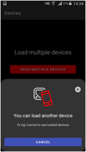
Touch the found LED module (“Robin T11 LED module”) and than touch “LED engine” to read information about found LED module.

DMX protocol
| Robin T15TM Fresnel/PC – DMX protocol | ||||||||
| Version: 1.0 | ||||||||
| Short desciption of modes | ||||||||
| Mode | Description | |||||||
| 1 | 16-bit CMY/RGB, 20 channels in total | |||||||
| 2 | 8-bit CMY/RGB, 10 channels in total | |||||||
| 3 | 16-bit RGBAL, 24 channels in total | |||||||
| 4 | White light+zoom & dimmer , 7 channels in total | |||||||
| 5 | Zoom & Dimmer , 2 channels in total | |||||||
| 6 | Only Dimmer, 1 channel in total | |||||||
| Quick overview of default DMX values for each channel | ||||||||
| Mode/channel | Default DMX Value | Function | ||||||
| 1 | 2 | 3 | 4 | 5 | 6 | |||
| 1 | 1 | 1 | * | * | * | 0 | Power/Special functions | |
| 2 | * | 2 | * | * | * | 10 | LED frequency selection | |
| 3 | * | 3 | * | * | * | 128 | LED frequency fine adjusting | |
| 4 | 2 | 4 | * | * | * | 0 | Colour functions | |
| 5 | 3 | 5 | 1 | * | * | 0 | CRI selection | |
| 6 | * | 6 | * | * | * | 0 | Virtual colour wheel | |
| 7 | 4 | * | * | * | * | 0/255 | Cyan/Red (8 bit) (0=default for CMY mode, 255=default for RGB mode) | |
| 8 | * | * | * | * | * | 0/255 | Cyan/Red (16 bit) (0=default for CMY mode, 255=default for RGB mode) | |
| 9 | 5 | * | * | * | * | 0/255 | Magenta/Green (8 bit) (0=default for CMY mode, 255=default for RGB mode) | |
| 10 | * | * | * | * | * | 0/255 | Magenta/Green (16 bit) (0=default for CMY mode, 255=default for RGB mode) | |
| 11 | 6 | * | * | * | * | 0/255 | Yellow/Blue (8 bit) (0=default for CMY mode, 255=default for RGB mode) | |
| 12 | * | * | * | * | * | 0/255 | Yellow/Blue (16 bit) (0=default for CMY mode, 255=default for RGB mode) | |
| * | * | 7 | * | * | * | 255 | Red (8 bit) | |
| * | * | 8 | * | * | * | 255 | Red (16bit) | |
| * | * | 9 | * | * | * | 255 | Green (8 bit) | |
| * | * | 10 | * | * | * | 255 | Green (16bit) | |
| * | * | 11 | * | * | * | 255 | Blue (8 bit) | |
| * | * | 12 | * | * | * | 255 | Blue (16bit) | |
| * | * | 13 | * | * | * | 255 | Amber (8 bit) | |
| * | * | 14 | * | * | * | 255 | Amber (16bit) | |
| * | * | 15 | * | * | * | 255 | Lime (8 bit) | |
| * | * | 16 | * | * | * | 255 | Lime (16bit) | |
| 13 | 7 | 17 | 2 | * | * | 110 | Colour temperature correction (CCT) | |
| 14 | * | 18 | 3 | * | * | 128 | Green correction | |
| 15 | * | 19 | * | * | * | 0 | Colour mix control | |
| 16 | 8 | 20 | 4 | 1 | * | 128 | Zoom (8-bit) | |
| 17 | * | 21 | 5 | * | * | 0 | Zoom (16-bit) | |
| 18 | 9 | 22 | * | * | * | 32 | Shutter/ strobe | |
| 19 | 10 | 23 | 6 | 2 | 1 | 0 | Dimmer intensity (8-bit) | |
| 20 | * | 24 | 7 | * | * | 0 | Dimmer intensity (16-bit) | |
| Mode/channel | DMX Value | Function | Type of control | |||||
| 1 | 2 | 3 | 4 | 5 | 6 | |||
| 1 | 1 | 1 | * | * | * | Power/Special functions | ||
| 0 -19 | Reserved (0=default) | |||||||
| To activate following functions, stop in DMX value for at least 3 s and shutter must be closed at least 3 sec. („Shutter,Strobe” channel 18/9/22 must be at range: 0-31 DMX). Corresponding menu items are temporarily overriden. | ||||||||
| 20-24 | Display: On | step | ||||||
| 25-29 | Display: Off | step | ||||||
| 30-69 | Reserved | |||||||
| 70-74 | Fans mode: Auto | step | ||||||
| 75-79 | Reserved | |||||||
| 80-84 | Quiet mode: Fans On at blackout | step | ||||||
| 85-89 | Quiet mode: Fans Off at blackout | step | ||||||
| 90-129 | Reserved | |||||||
| To activate following functions, stop in DMX value for at least 3 seconds. | ||||||||
| 130-134 | Simple mode off | step | ||||||
| 135-159 | Zoom reset | step | ||||||
| 160-235 | Reserved | |||||||
| 236-237 | Optics brake On | step | ||||||
| 238-239 | Optics brake Off | step | ||||||
| 240 | Disabled “Quiet mode” | step | ||||||
| 241-255 | Quiet mode – fan noise control from min. to max. | proportional | ||||||
| 2 | * | 2 | * | * | * | LED frequency selection | ||
| Factory display menu setting: 600Hz | ||||||||
| Select PWM output frequency of LEDs. Selected PWM frequency can be fine adjusted in 127 steps up/down around selected PWM frequency on the channel below. Corresponding menu item (Frequency Setup) is temporarily overriden. | ||||||||
| 0-4 | PWM frequency from Display menu (fixture utilizes PWM | step | ||||||
| frequency set in the display menu item Frequency Setup). | ||||||||
| 5-9 | 300 Hz | step | ||||||
| 10-14 | 600 Hz (10=default) | step | ||||||
| 15-19 | 1200 Hz | step | ||||||
| 20-24 | 2400 Hz | step | ||||||
| 25-29 | High | step | ||||||
| 30-255 | Reserved (fixture utilizes PWM frequency set in the display menu item | |||||||
| Frequency Setup). | ||||||||
| 3 | * | 3 | * | * | * | LED frequency fine adjusting | ||
| Factory display menu setting: 600Hz | ||||||||
| Select desired PWM output frequency of LEDs on the channel above. | ||||||||
| 0-1 | Selected LED Frequency | step | ||||||
| 2 | LED Frequency (step -126) | step | ||||||
| 3 | LED Frequency (step -125) | step | ||||||
| 4 | LED Frequency (step -124) | step | ||||||
| : | ||||||||
| 125 | LED Frequency (step -3) | step | ||||||
| 126 | LED Frequency (step -2) | step | ||||||
| Mode/channel | DMX Value | Function | Type of control | |||||
| 1 | 2 | 3 | 4 | 5 | 6 | |||
| 127 | LED Frequency (step -1) | step | ||||||
| 128 | Selected LED Frequency (128=default) | step | ||||||
| 129 | LED Frequency (step +1) | step | ||||||
| 130 | LED Frequency (step +2) | step | ||||||
| 131 | LED Frequency (step +3) | step | ||||||
| : | ||||||||
| 252 | LED Frequency (step +124) | step | ||||||
| 253 | LED Frequency (step +125) | step | ||||||
| 254 | LED Frequency (step +126) | step | ||||||
| 255 | Selected LED Frequency | step | ||||||
| 4 | 2 | 4 | * | * | * | Colour functions | ||
| Factory display menu setting: Colour mixing mode-CMY, Dimmer Curve-Square Law, Tungsten effect simulation-Off, Chromatic white- Off, Light output stability-Off, Uniformity-Off | ||||||||
| 0 | No function (0=default) | step | ||||||
| To activate following functions, stop in DMX value for at least 3 seconds. Corresponding menu items are temporarily overriden |
||||||||
| 1-39 | Reserved | |||||||
| 40-44 | Colour mixing mode: CMY (DMX Mode 1, 2 only) | step | ||||||
| 45-49 | Colour mixing mode: RGB (DMX mode 1, 2 only), RGBAL (DMX mode 3 only) | step | ||||||
| 50-54 | Dimmer curve: Square law | step | ||||||
| 55-59 | Dimmer curve: Linear | step | ||||||
| 60-64 | Dimmer curve: Super square law | step | ||||||
| 65-79 | Raw DMX | proportional | ||||||
| Tungsten effect simulation for whites 2700K-4200K only: | ||||||||
| 80-84 | Tungsten effect simulation (750W/80V): On | step | ||||||
| 85-89 | Tungsten effect simulation (1000W/240V): On | step | ||||||
| 90-94 | Tungsten effect simulation (1200W/240V): On | step | ||||||
| 95-99 | Tungsten effect simulation (2000W/230V): On | step | ||||||
| 100-104 | Tungsten effect simulation (2500W/230V): On | step | ||||||
| 105-109 | Tungsten effect simulation: Off | step | ||||||
| 110-114 | Save user colour (see user manual) | step | ||||||
| 115-119 | Chromatic white: On | step | ||||||
| 120-124 | Chromatic white: Off | step | ||||||
| 125-129 | Light output stability On | step | ||||||
| 130-134 | Light output stability Off | step | ||||||
| 135-139 | Uniformity On | step | ||||||
| 140-144 | Uniformity Off | step | ||||||
| 145-255 | Reserved | |||||||
| 5 | 3 | 5 | 1 | * | * | CRI selection | ||
| 0-255 | CRI selection from Standard (80) to High (90+) (0=default) | proportional | ||||||
| 6 | * | 6 | * | * | * | Virtual colour wheel | ||
| 0 | No function (0=default) | step | ||||||
| 1-2 | Filter 4 (Medium Bastard Amber) | step | ||||||
| 3-4 | Filter 10 (Medium Yellow) | step | ||||||
| 5-6 | Filter 19 (Fire) | step | ||||||
| 7-8 | Filter 26 (Bright Red) | step | ||||||
| 9-10 | Filter 58 (Lavender) | step | ||||||
| 11-12 | Filter 68 (Sky Blue) | step | ||||||
| Mode/channel | DMX Value | Function | Type of control | |||||
| 1 | 2 | 3 | 4 | 5 | 6 | |||
| 13-14 | Filter 71 (Tokyo Blue) | step | ||||||
| 15-16 | Filter 79 (Just Blue) | step | ||||||
| 17-18 | Filter 88 (Lime Green) | step | ||||||
| 19-20 | Filter 90 (Dark Yellow Green) | step | ||||||
| 21-22 | Filter 100 (Spring Yellow) | step | ||||||
| 23-24 | Filter 101 (Yellow) | step | ||||||
| 25-26 | Filter 102 (Light Amber) | step | ||||||
| 27-28 | Filter 103 (Straw) | step | ||||||
| 29-30 | Filter 104 (Deep Amber) | step | ||||||
| 31-32 | Filter 105 (Orange) | step | ||||||
| 33-34 | Filter 106 (Primary Red) | step | ||||||
| 35-36 | Filter 111 (Dark Pink) | step | ||||||
| 37-38 | Filter 115 (Peacock Blue) | step | ||||||
| 39-40 | Filter 116 (Medium Blue-Green) | step | ||||||
| 41-42 | Filter 117 (Steel Blue) | step | ||||||
| 43-44 | Filter 118 (Light Blue) | step | ||||||
| 45-46 | Filter 119 (Dark Blue) | step | ||||||
| 47-48 | Filter 120 (Deep Blue) | step | ||||||
| 49-50 | Filter 121 (Filter Green) | step | ||||||
| 51-52 | Filter 128 (Bright Pink) | step | ||||||
| 53-54 | Filter 131 (Marine Blue) | step | ||||||
| 55-56 | Filter 132 (Medium Blue) | step | ||||||
| 57-58 | Filter 134 (Golden Amber) | step | ||||||
| 59-60 | Filter 135 (Deep Golden Amber) | step | ||||||
| 61-62 | Filter 136 (Pale Lavender) | step | ||||||
| 63-64 | Filter 137 (Special Lavender) | step | ||||||
| 65-66 | Filter 138 (Pale Green) | step | ||||||
| 67-68 | Filter 139 (Primary Green) | step | ||||||
| 69-70 | Filter 141 (Bright Blue) | step | ||||||
| 71-72 | Filter 147 (Apricot) | step | ||||||
| 73-74 | Filter 148 (Bright Rose) | step | ||||||
| 75-76 | Filter 152 (Pale Gold) | step | ||||||
| 77-78 | Filter 154 (Pale Rose) | step | ||||||
| 79-80 | Filter 157 (Pink) | step | ||||||
| 81-82 | Filter 158 (Deep Orange) | step | ||||||
| 83-84 | Filter 162 (Bastard Amber) | step | ||||||
| 85-86 | Filter 164 (Flame Red) | step | ||||||
| 87-88 | Filter 165 (Daylight Blue) | step | ||||||
| 89-90 | Filter 169 (Lilac Tint) | step | ||||||
| 91-92 | Filter 170 (Deep Lavender) | step | ||||||
| 93-94 | Filter 172 (Lagoon Blue) | step | ||||||
| 95-96 | Filter 179 (Chrome Orange) | step | ||||||
| 97-98 | Filter 180 (Dark Lavender) | step | ||||||
| 99-100 | Filter 181 (Congo Blue) | step | ||||||
| 101-102 | Filter 197 (Alice Blue) | step | ||||||
| 103-104 | Filter 201 (Full C.T. Blue) | step | ||||||
| 105-106 | Filter 202 (Half C.T. Blue) | step | ||||||
| 107-108 | Filter 203 (Quarter C.T. Blue) | step | ||||||
| Mode/channel | DMX Value | Function | Type of control | |||||
| 1 | 2 | 3 | 4 | 5 | 6 | |||
| 109-110 | Filter 204 (Full C.T. Orange) | step | ||||||
| 111-112 | Filter 205 (Half C.T. Orange) | step | ||||||
| 113-114 | Filter 206 (Quarter C.T. Orange) | step | ||||||
| 115-116 | Filter 247 (Filter Minus Green) | step | ||||||
| 117-118 | Filter 248 (Half Minus Green) | step | ||||||
| 119-120 | Filter 281 (Three Quarter C.T. Blue) | step | ||||||
| 121-122 | Filter 285 (Three Quarter C.T. Orange) | step | ||||||
| 123-124 | Filter 352 (Glacier Blue) | step | ||||||
| 125-126 | Filter 353 (Lighter Blue) | step | ||||||
| 127-128 | Filter 715 (Cabana Blue) | step | ||||||
| 129-130 | Filter 778 (Millennium Gold) | step | ||||||
| 131-132 | Filter 793 (Vanity Fair) | step | ||||||
| 133-215 | Reserved | |||||||
| 216-217 | User colour 1 | step | ||||||
| 218-219 | User colour 2 | step | ||||||
| 220-221 | User colour 3 | step | ||||||
| 222-223 | User colour 4 | step | ||||||
| 224-225 | User colour 5 | step | ||||||
| 226-227 | User colour 6 | step | ||||||
| 228-229 | User colour 7 | step | ||||||
| 230-231 | User colour 8 | step | ||||||
| 232-233 | User colour 9 | step | ||||||
| 234-235 | User colour 10 | step | ||||||
| 236-245 | Rainbow effect (with fade time) from slow-> fast | proportional | ||||||
| 246-255 | Rainbow effect (without fade time) from slow-> fast | proportional | ||||||
| 7 | 4 | * | * | * | * | Cyan/Red (8 bit) | ||
| 0 – 255 | Colour saturation control – coarse 0-100% (0=default for CMY mode, 255=default for RGB mode) | proportional | ||||||
| 8 | * | * | * | * | * | Cyan/Red (16 bit) | ||
| 0 – 255 | Colour saturation control – fine (0=default for CMY mode, 255=default for RGB mode) | proportional | ||||||
| 9 | 5 | * | * | * | * | Magenta/Green (8 bit) | ||
| 0 – 255 | Colour saturation control – coarse 0-100% (0=default for CMY mode, 255=default for RGB mode) | proportional | ||||||
| 10 | * | * | * | * | * | Magenta/Green (16 bit) | ||
| 0 – 255 | Colour saturation control – fine (0=default for CMY mode, 255=default for RGB mode) | proportional | ||||||
| 11 | 6 | * | * | * | * | Yellow/Blue (8 bit) | ||
| 0 – 255 | Colour saturation control – coarse 0-100% (0=default for CMY mode, 255=default for RGB mode) | proportional | ||||||
| 12 | * | * | * | * | * | Yellow/Blue (16 bit) | ||
| 0 – 255 | Colour saturation control – fine (0=default for CMY mode, 255=default for RGB mode) | proportional | ||||||
| * | * | 7 | * | * | * | Red (8 bit) | ||
| 0 – 255 | Colour saturation control – coarse 0-100% (255=default) | proportional | ||||||
| * | * | 8 | * | * | * | Red (16bit) | ||
| 0 – 255 | Colour saturation control – fine (255=default) | proportional | ||||||
| * | 9 | * | * | * | Green (8 bit) | |||
| 0 – 255 | Colour saturation control – coarse 0-100% (255=default) | proportional | ||||||
| Mode/channel | DMX Value | Function | Type of control | |||||
| 1 | 2 | 3 | 4 | 5 | 6 | |||
| * | 10 | * | * | * | Green (16bit) | |||
| 0 – 255 | Colour saturation control – fine (255=default) | proportional | ||||||
| * | 11 | * | * | * | Blue (8 bit) | |||
| 0 – 255 | Colour saturation control – coarse 0-100% (255=default) | proportional | ||||||
| * | 12 | * | * | * | Blue (16bit) | |||
| 0 – 255 | Colour saturation control – fine (255=default) | proportional | ||||||
| * | 13 | * | * | * | Amber (8 bit) | |||
| 0 – 255 | Colour saturation control – coarse 0-100% (255=default) | proportional | ||||||
| * | 14 | * | * | * | Amber (16bit) | |||
| 0 – 255 | Colour saturation control – fine (255=default) | proportional | ||||||
| * | 15 | * | * | * | Lime (8 bit) | |||
| 0 – 255 | Colour saturation control – coarse 0-100% (255=default) | proportional | ||||||
| * | 16 | * | * | * | Lime (16bit) | |||
| 0 – 255 | colour saturation control – fine (255=default) | proportional | ||||||
| 13 | 7 | 17 | 2 | * | * | CTO | ||
| 0-1 | 8000 K | step | ||||||
| 2-64 | Colour temperature changing 7978 K ->6622 K (22 K /1 DMX) | proportional | ||||||
| 65 | 6600 K | step | ||||||
| 66-109 | Colour temperature changing 657 8K ->5622 K (22 K/1 DMX) | proportional | ||||||
| 110 | 5600 K (110=default) | step | ||||||
| 111-179 | Colour temperature changing 5580 K ->4220 K (20 K/1 DMX) | proportional | ||||||
| 180 | 4200 K | step | ||||||
| 181-229 | Colour temperature changing 4180 K ->3220 K (20 K/1 DMX) | proportional | ||||||
| 230 | 3200 K | step | ||||||
| 231-254 | Colour temperature changing 3180 K ->2720 K (20K /1 DMX) | proportional | ||||||
| 255 | 2700K | step | ||||||
| 14 | * | 18 | 3 | * | * | Green correction | ||
| 0 | Uncorrected white | step | ||||||
| 1-127 | Minus green –> uncorrected white | proportional | ||||||
| 128 | Uncorrected white (128=default) | step | ||||||
| 129-255 | Uncorrected white –> Plus green | proportional | ||||||
| 15 | * | 19 | * | * | * | Colour mix control | ||
| Defines relation between Virtual Colour wheel and colour channels | ||||||||
| “Virtual” = Virtual Colour Wheel | ||||||||
| “Colour mix” = Colour channels (CMY/RGBAL/CCT) | ||||||||
| 0-9 | “Virtual ” has priority over “Colour mix” (0=default) | |||||||
| 10-19 | Maximum mode (highest values have priority) | step | ||||||
| 20-29 | Minimum mode (lowest values have priority) | step | ||||||
| 30-39 | Multiply mode (multiply “Virtual” and “Colour mix”) | step | ||||||
| 40-49 | Addition mode (“Virtual” + “Colour mix”) | step | ||||||
| 50-59 | Subtraction mode (“Virtual” – “Colour mix”) | step | ||||||
| 60-69 | Inverted Subtraction mode (“Colour mix”-“Virtual”) | step | ||||||
| 70-79 | White Point Off (CCT+Green Cor.+Virtual Colour Wheel deactivated) | step | ||||||
| 80-128 | Reserved | |||||||
| 129 | Crossfade “Virtual” only | step | ||||||
| 130-254 | Crossfade between “Virtual” and “Colour mix” | proportional | ||||||
| 255 | Crossfade “Colour mix” only | step | ||||||
| Mode/channel | DMX Value | Function | Type of control | |||||
| 1 | 2 | 3 | 4 | 5 | 6 | |||
| 16 | 8 | 20 | 4 | 1 | * | Zoom (8-bit) | ||
| 0 – 255 | Zoom from max. to min.beam angle (128=default) | proportional | ||||||
| 17 | * | 21 | 5 | * | * | Zoom (16-bit) | ||
| 0-255 | Fine zooming (0=default) | proportional | ||||||
| 18 | 9 | 22 | * | * | * | Shutter/ strobe | ||
| 0 – 31 | Shutter closed | step | ||||||
| 32 – 63 | Shutter open (32=default) | step | ||||||
| 64 – 95 | Strobe-effect from slow to fast | proportional | ||||||
| 96 – 127 | Shutter open | step | ||||||
| 128 – 143 | Opening pulse in sequences from slow to fast | proportional | ||||||
| 144 – 159 | Closing pulse in sequences from fast to slow | proportional | ||||||
| 160 – 191 | Shutter open | step | ||||||
| 192 – 223 | Random strobe-effect from slow to fast | proportional | ||||||
| 224 – 255 | Shutter open | step | ||||||
| 19 | 10 | 23 | 6 | 2 | 1 | Dimmer intensity (8-bit | ||
| 0 – 255 | Dimmer intensity from 0% to 100% (0=default) | proportional | ||||||
| 20 | * | 24 | 7 | * | * | Dimmer intensity (16-bit) | ||
| 0 – 255 | Fine dimming (0=default) | proportional | ||||||
| Copyright © 2023 Robe Lighting s.r.o. – All rights reserved | ||||||||
| All Specifications subject to change without notice | ||||||||
| T15 – Colours on Virtual Colour Wheel | |||||
| Colour name | Red DMX | Green DMX | Blue DMX | Amber DMX | Lime DMX |
| Filter 4 (Medium Bastard Amber) | 255 | 47 | 7 | 255 | 80 |
| Filter 10 (Medium Yellow) | 255 | 65 | 0 | 255 | 132 |
| Filter 19 (Fire) | 255 | 0 | 0 | 186 | 1 |
| Filter 26 (Bright Red) | 255 | 0 | 0 | 25 | 0 |
| Filter 58 (Lavender) | 255 | 0 | 68 | 255 | 44 |
| Filter 68 (Sky Blue) | 132 | 190 | 159 | 0 | 36 |
| Filter 71 (Tokyo Blue) | 0 | 0 | 255 | 0 | 0 |
| Filter 79 (Just Blue) | 123 | 147 | 171 | 0 | 56 |
| Filter 88 (Lime Green) | 255 | 237 | 2 | 198 | 185 |
| Filter 90 (Dark Yellow Green) | 0 | 255 | 2 | 0 | 169 |
| Filter 100 (Spring Yellow) | 255 | 0 | 0 | 255 | 223 |
| Filter 101 (Yellow) | 255 | 0 | 0 | 255 | 157 |
| Filter 102 (Light Amber) | 255 | 142 | 4 | 255 | 73 |
| Filter 103 (Straw) | 255 | 138 | 4 | 255 | 97 |
| Filter 104 (Deep Amber) | 255 | 0 | 0 | 255 | 124 |
| Filter 105 (Orange) | 255 | 0 | 0 | 255 | 60 |
| Filter 106 (Primary Red) | 255 | 0 | 0 | 104 | 0 |
| Filter 111 (Dark Pink) | 255 | 0 | 11 | 255 | 59 |
| Filter 115 (Peacock Blue) | 0 | 255 | 31 | 0 | 72 |
| Filter 116 (Medium Blue-Green) | 0 | 255 | 20 | 0 | 63 |
| Filter 117 (Steel Blue) | 45 | 255 | 42 | 158 | 183 |
| Filter 118 (Light Blue) | 4 | 255 | 37 | 0 | 77 |
| Filter 119 (Dark Blue) | 0 | 165 | 118 | 0 | 0 |
| Filter 120 (Deep Blue) | 3 | 165 | 111 | 0 | 0 |
| Filter 121 (Filter Green) | 84 | 255 | 0 | 235 | 24 |
| Filter 128 (Bright Pink) | 255 | 0 | 10 | 127 | 0 |
| Filter 131 (Marine Blue) | 0 | 255 | 75 | 51 | 116 |
| Filter 132 (Medium Blue) | 0 | 255 | 102 | 0 | 42 |
| Filter 134 (Golden Amber) | 255 | 51 | 0 | 255 | 42 |
| Filter 135 (Deep Golden Amber) | 255 | 35 | 0 | 255 | 0 |
| Filter 136 (Pale Lavender) | 184 | 7 | 51 | 255 | 60 |
| Filter 137 (Special Lavender) | 231 | 63 | 43 | 255 | 99 |
| Filter 138 (Pale Green) | 255 | 224 | 6 | 255 | 200 |
| Filter 139 (Primary Green) | 0 | 255 | 0 | 0 | 84 |
| Filter 141 (Bright Blue) | 0 | 255 | 77 | 0 | 82 |
| Filter 147 (Apricot) | 255 | 0 | 4 | 255 | 115 |
| Filter 148 (Bright Rose) | 255 | 0 | 7 | 255 | 13 |
| Filter 152 (Pale Gold) | 255 | 0 | 11 | 255 | 112 |
| Filter 154 (Pale Rose) | 255 | 0 | 16 | 255 | 119 |
| Filter 157 (Pink) | 255 | 0 | 7 | 255 | 27 |
| Filter 158 (Deep Orange) | 255 | 0 | 0 | 255 | 30 |
| Filter 162 (Bastard Amber) | 255 | 175 | 7 | 255 | 50 |
| Filter 164 (Flame Red) | 255 | 0 | 0 | 142 | 0 |
| Filter 165 (Daylight Blue) | 12 | 255 | 158 | 3 | 156 |
| Filter 169 (Lilac Tint) | 255 | 12 | 27 | 255 | 61 |
| Filter 170 (Deep Lavender) | 255 | 0 | 65 | 255 | 90 |
| Filter 172 (Lagoon Blue) | 0 | 238 | 113 | 0 | 255 |
| Colour name | Red DMX | Green DMX | Blue DMX | Amber DMX | Lime DMX |
| Filter 179 (Chrome Orange) | 255 | 0 | 0 | 255 | 112 |
| Filter 180 (Dark Lavender) | 92 | 15 | 188 | 76 | 46 |
| Filter 181 (Congo Blue) | 185 | 0 | 214 | 0 | 0 |
| Filter 197 (Alice Blue) | 0 | 249 | 163 | 39 | 0 |
| Filter 201 (Full C.T. Blue) | 38 | 150 | 97 | 36 | 246 |
| Filter 202 (Half C.T. Blue) | 164 | 13 | 123 | 34 | 255 |
| Filter 203 (Quarter C.T. Blue) | 255 | 203 | 54 | 104 | 255 |
| Filter 204 (Full C.T. Orange) | 255 | 125 | 0 | 255 | 4 |
| Filter 205 (Half C.T. Orange) | 255 | 139 | 5 | 255 | 67 |
| Filter 206 (Quarter C.T. Orange) | 255 | 60 | 17 | 255 | 98 |
| Filter 247 (Filter Minus Green) | 255 | 28 | 36 | 255 | 56 |
| Filter 248 (Half Minus Green) | 255 | 20 | 45 | 255 | 200 |
| Filter 281 (Three Quarter C.T. Blue) | 38 | 255 | 102 | 136 | 227 |
| Filter 285 (Three Quarter C.T. Orange) | 255 | 0 | 0 | 255 | 121 |
| Filter 352 (Glacier Blue) | 16 | 255 | 119 | 5 | 149 |
| Filter 353 (Lighter Blue) | 14 | 255 | 66 | 0 | 157 |
| Filter 715 (Cabana Blue) | 0 | 222 | 182 | 0 | 0 |
| Filter 778 (Millennium Gold) | 255 | 0 | 0 | 255 | 37 |
| Filter 793 (Vanity Fair) | 255 | 0 | 26 | 171 | 0 |
![]()
Documents / Resources
 |
ROBe T15PC Fresnel Multisource LED Static Light [pdf] User Manual T15 PC, T15 Fresnel, T15PC Fresnel Multisource LED Static Light, T15PC, Fresnel Multisource LED Static Light, Multisource LED Static Light, LED Static Light, Static Light, Light |


