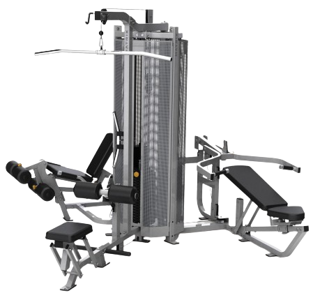
MATRIX GM167F 3 Stack Multi Gym
Product Information
Proper Usage
- Do not exceed weight limits of the exercise device.
- If applicable, set safety stops to appropriate height.
- If applicable, adjust seat pads, leg pads, foot pads, range of motion adjustment, or any other type of adjustment mechanisms to a comfortable start position. Make certain that the adjusting mechanism is fully engaged to prevent unintentional movement and to avoid injury.
- Sit on bench (if applicable) and get into appropriate position for exercise.
- Exercise using no more weight than you can safely lift and control.
- In a controlled manner, perform exercise.
- Return weight to its fully-supported start position.
Product Specifications
| Max User Weight | 159 kg/ 350 lbs |
| Max Training Weight | 91 kg / 200 lbs |
| Product Weight | 592 kg / 1305 lbs |
| Overall Dimensions(L x W x H)* | 282 x 323 x 218 cm /111 x 127 x 86” |
* Ensure a minimum clearance width of 0.6 meters (24”) for access to and passage around MATRIX strength equipment. Please note, 0.91 meters (36”) is the ADA recommended clearance width for individuals with wheelchairs.
Torque Values
| M12 Bolt (Nyloc Nut & Flow drill) | 135 Nm / 100 ft-lbs |
| M10 Bolt (Nyloc Nut & Flow drill) | 77 Nm / 57 ft-lbs |
| M8 Bolts | 25 Nm / 18 ft-lbs |
| M8 Plastic | 15 Nm / 11 ft-lbs |
| M6 Bolts | 51 Nm / 11 ft-lbs |
| Pad Bolts | 10 Nm / 7 ft-lbs |
Installation
- STABLE AND LEVEL SURFACE: MATRIX exercise equipment must be installed on a stable base and properly leveled.
- SECURING EQUIPMENT: Manufacturer recommends that all stationary MATRIX strength equipment be secured to the floor to stabilize equipment and eliminate rocking or tipping over. This must be performed by a licensed contractor.
- Under no circumstances should you slide equipment across the floor due to risk of tipping. Use proper materials handling techniques and equipment recommended by OSHA.
All anchor points must be able to withstand 750 lbs. (3.3 kN) pull-out force.
Maintenance
- DO NOT use any equipment that is damaged and or has worn or broken parts. Use only replacement parts supplied by your country’s local MATRIX dealer.
- MAINTAIN LABELS AND NAMEPLATES: Do not remove labels for any reason. They contain important information. If unreadable or missing, contact your MATRIX dealer for a replacement.
- MAINTAIN ALL EQUIPMENT: Preventative maintenance is the key to smooth operating equipment as well as keeping your liability to a minimum. Equipment needs to be inspected at regular intervals.
- Ensure that any person(s) making adjustments or performing maintenance or repair of any kind is qualified to do so. MATRIX dealers will provide service and maintenance training at our corporate facility upon request.
Maintenance Checklist
| Clean Upholstery (¹) | Daily |
| Inspect Cables (²) | Daily |
| Clean Guide Rods | Monthly |
| Inspect Hardware | Monthly |
| Inspect Frame | Bi-Annualy |
| Clean Machine | As Needed |
| Clean Grips (¹) | As Needed |
| Lubricate Guide Rods (³) | As Needed |
- Upholstery & grips should be cleaned with a mild soap and water or a non-ammonia based cleaner.
- Cables should be inspected for cracks or frays and immediately replaced if present. If excessive slack exists the cable should be tightened without lifting the head plate.
- Guide rods should be lubricated with Teflon based lubricant. Apply the lubricant to a cotton cloth and then apply up and down the guide rods.
Inspect Cables (Weekly)
It is important for a facility to check cable conditions weekly.
Fractures:
Casing can crack or fracture under strains during use. Any crack in the casing merits cable replacement even if no wire rope is exposed. Be especially observant for fractures near the components on the cable assembly.
 Twisting/Binding:
Inspect casing to ensure wire rope is not twisting within its casing. Any sign of the cable twisting should be replaced immediately.

Bulging:
Internal wire rope strands can break within and coil causing a bulge to appear. Cable should retain same outside diameter throughout.

Frayed/Exposed Wire:
Any exposed wire rope protruding through the casing or at either end. 
Flattened:
A section of cable is compressed and will not retain its shape (outside diameter).

Bent:
Cable has ‘kink’ and prohibits cable from laying straight. Wire rope may be unraveling beneath casing and is compromised warranting replacement.

Ends Separating:
Watch for component end of cable to pull away from cable assembly – look for exposed wire rope. Often times the oil from inside the cable jacket will start to leak out which can cause the cable to become brittle over time.

Tensioning Cables (As needed)
Cables can stretch over their life. It’s important to check for proper tension and inspect for damage. Without proper tension, users will lose some range of motion and excess wear to the cables can occur.
Checking Tension:
- Unpin the weight stack pin from the stack.
- From the midway point of the cable bolt and top of weight stack, use your finger to move the cable from side to side. You should see no more than ½” (13mm) of deflection (about the width of your finger) before the top weight plate starts to move or you feel resistance from the cable.
- If you have more than ½” (13mm) of deflection, follow the tensioning procedure on the following pages.

Tensioning Procedure:
- Unpin the weight stack pin from the stack.
- Remove the cable bolt from the head plate adapter.
A minimum of (13mm) of the cable bolt must be engaged into the head plate adapter. Strength cable bolts vary in length. Remove the bolt and measure it. Install it so a minimum of h” (13mm) is engaged into head plate. Turn down as needed based on cable tension (deflection).
- Turn down the cable bolt so ½” (13mm) of the bolt is engaged into the head plate adapter (see image to the right)
- Check cable tension. If you have no more than ½” (13mm) deflection the cable is tensioning properly (see checking for proper tension procedure above)
- If you have too much deflection, turn the cable bolt down a few turns and check tension again. Do this
Lubricating Guide Rods (Monthly)
Matrix Fitness requires PTFE based non-aerosol lubricants
Note: PTFE is Polytetrafluoroethylene (Teflon)
Procedure:
- With a clean rag, wipe the guide rods and top of the weight stack so they are free of dirt and dust.
- Spray a different rag with the required lubricant and wipe up and down the guide rod gently.
- Holding the lubricant bottle 1”-2” from the top weight plate bushings, spray a small amount of lubricant between the bushing and the guide rod. Allow the lubricant to run down the guide rod inside the weight stack.

- Get on the unit and with a light weight, do a few reps. Listen for noise and feel for any friction. Repeat Step 3 and 4 as necessary.
- Wipe any overspray off the top weight plate.
Inspect Hardware (Monthly)
As equipment settles to the floor after being relocated and general use, frame bolts may begin to loosen. If this is noticed, follow the below steps to secure the bolt. It is best to do this repair at the end of the day as the facility slows down as it may take 24 hours for the VibraTite to cure/set.
- Loosen the bolt in question to expose the bolt threads.
- Apply VibraTite red thread locker to the bolt threads.
- Tighten the bolt.
Checking Bearings (Monthly)
Bearings play a vital role in the functionality of moving parts. However, over time, these bearings are susceptible to wear and damage. Therefore, it is essential to regularly check for any signs of bearing damage. To assess bearing condition, utilize two senses: touch and hearing. By feeling and listening to the movement of the frame, you can detect potential issues with the bearings. If you suspect that a bearing is damaged, it is crucial to take immediate action and replace it promptly. By proactively monitoring and addressing bearing damage, you can ensure the smooth and efficient operation of the machine, prolonging its lifespan and reducing the risk of malfunctions.
Cleaning
Machines should be regularly cleaned. Approved cleaning materials and information can be found in the guide Cleaners, Disinfectants, and Lubricants (NB-2401006) bulletin listed on Online Remedy and CSWeb.
Supplemental Documentation
- Online Remedy and CSWeb contains additional supplementation for Matrix products that have a wealth of information that may not be explicitly covered in this document.
- Cleaners, Disinfectants, and Lubricants (NB-2401006)
- Strength Cable and Belt Guide (NB-2401007)
- Cleaning and Maintenance Checklist – Strength (NB-2401008)
- Assembly and Installation Guidelines (NB-2401009)
Assembly Guides
Below are the assembly guides for each model. Assembly guides can also be found in each frame’s individual Owner’s Manual. Strength equipment must be secured to the floor after assembly is complete.
Leveling and Securing Strength Equipment
Leveling
Composite leveling shims can be used to help level equipment when the floor is not level. Another tip is to loosen your frame bolts and give the machine a shake if possible. This may adjust the frame pieces a bit allowing it to sit better on the floor. Tighten all bolts once you are done.
Securing Strength Equipment
Matrix Fitness recommends that all stationary strength equipment be secured to the floor or wall to stabilize equipment and eliminate rocking or tipping over. Matrix requires specific pull-out force requirements shown below. Use a licensed contractor to ensure the required retention force is met.
All Flooring
- Each anchoring fastener must withstand 3.3 kN (750 LBS) pull-out force from the floor.
- Anchor the exercise equipment at all provided locations.
- Understand where all bolt-down points are located on the exercise equipment and mark the locations prior to drilling holes into the floor.
Wood/Tile/Rubber Over Concrete Sub-floor
- Understand the thickness of the flooring material. Add this height to the overall length of the anchoring fastener when selecting fastener length to ensure proper embedded depth into concrete flooring.
Frame Connections
- Any frame connection bolt should have VibraTite Red Gel applied to the threads during assembly or anytime the bolt is used to re-assemble a unit.

- M12 bolts should be torqued to 100 N-m if it is being used with anyloc nut.
- M12 bolts should be torqued to 100 N-m if it is being used in a rivnut. VibraTite Red Gel should be applied to the bolt threads after assembling the washer

Assembly Guide
Step 1 Step 2

Step 3 
Step 4
Step 5
Step 6
Step 7
Step 8
Part Replacement
Flat Pad Replacement
- All flat plads on this unit have four bolts securing them to the base frame.
- Access to the bolts securing the pad is gained from the underside.
- Pad bolts should be torqued to 10 Nm / 7 ft-lbs.


Round Pad Replacement (Snap Ring)
- This frame features two types of round pads: one secured by a snap ring, the other by a bolt.
- Snap ring can be removed by a 12” snap ring pliers.
- Remove the end cap and remove the pad from the frame, and then remove the two inserted end covers.
- Reverse steps 1-3 to install the pad.

Round Pad Replacement (Bolted)
- This frame features two types of round pads: one secured by a snap ring, the other by a bolt.
- Remove the bolt securing the pad to the frame.
- Remove the washer and disc securing the pad to the frame, and then remove the pad.
- Remove the larger-disc (the one with the bigger hole positioned between the frame and pad) – note there are two different-sized discs on the frame.
- Reverse steps 1-4 to install the pad.

Cable Diagram – Multi-Position Press 
 Cable Diagram – Leg Extension Curl


Cable Diagram – Lat Pulldown / Low Row
The Lat Pulldown / Low Row has two cables labeled as green and red in the diagram below. 
Handlebar Foam Replacement
- Remove the two set screws.
- Remove the Grip Cap from the handlebar.
- Remove the Grip from the frame, if necessary this can be carefully cut off.
- Fully scour the frame underneath the foam, the frame where the foam should be placed needs to be entirely clean before the replacement is installed.
- To ease installation, lightly apply warm soapy water to the inside of the handlebar foam and the corresponding section of the handlebar frame. This lubrication helps the foam grip slide smoothly into position.
- Reinstall the grip cap and set screws.

Change Log
| Version | Date | Name | Change |
| V1.0 | 5/06/2025 | Maxwell | Original Document |
Frequently Asked Questions
- Q: What should I do if the equipment is damaged?
A: Do not use the equipment if it is damaged. Contact your local MATRIX dealer for replacement parts. - Q: How often should I inspect the equipment for maintenance?
A: Equipment should be inspected at regular intervals for preventative maintenance to ensure smooth operation and minimize liability.
Documents / Resources
 |
MATRIX GM167F 3 Stack Multi Gym [pdf] Instruction Manual GM167F, GM167F 3 Stack Multi Gym, GM167F, 3 Stack Multi Gym, Stack Multi Gym, Multi Gym |