ICON PROCESS CONTROLS TVL Series Tank Level Display and Controller
![]()
Specifications
General
- Display: Displayed Values Stability Transmission Parameters Protection Class
Input Signal Supply
- Standard Voltage: Current: 4-20mA 0-20mA 0-5V* 0-10V* 85 – 260V AC/DC 16 – 35V AC, 19 – 50V DC*
Output Signal Supply
- Standard Voltage: Passive current output * 2 x Relays (5A) 1 x Relay (5A) + 4-20mA 24VDC 4-20mA (Operating Range Max. 2.8 – 24mA)
Performance
- Accuracy: According to IEC 60770 – Limit Point Adjustment Non-Linearity Hysteresis Repeatability
Temperatures
- Operating Temperatures
Materials Wetted
- Housing: Polycarbonate
Part Number
- TVL-550-1821
- TVL-550-1829
Product Usage Instructions
Basic Requirements
- Do not use the unit in areas threatened with excessive shocks, vibrations, dust, humidity, corrosive gasses, and oils.
- Do not use the unit in areas where there is a risk of explosions.
- Do not use the unit in areas with significant temperature variations, or exposure to condensation, or ice.
- The manufacturer is not responsible for any damages caused by inappropriate installation, not maintaining the proper environmental conditions, and using the unit contrary to its assignment.
- If there is a risk of a serious threat to safety in case of unit malfunction, additional independent systems should be used.
- The unit uses dangerous voltage; ensure it is switched off and disconnected from power before troubleshooting.
- Avoid disassembling, repairing, or modifying the unit yourself.
- Defective units should be submitted for repairs at an authorized service center.
Front Panel Description
- The front panel includes features like Alarm LED indicators, an Infrared Receiver, a Bright Large Display, Programming Buttons, and Function Push Buttons.
Wiring Diagram
- Refer to the wiring diagram for proper installation. Ensure correct connections based on the relay configuration and sensor input/output requirements.
WIRE INSTALLATION
- To prevent interference in industrial installations, follow appropriate measures to ensure the unit operates correctly.
FAQ
Q: Can I repair the unit myself if it malfunctions?
A: No, do not attempt to repair or modify the unit yourself.
Defective units should be submitted for repairs at an authorized service center.
Q: What should I do if the unit is exposed to extreme temperatures?
A: Do not use the unit in areas with significant temperature variations, exposure to condensation, or ice. Ensure proper environmental conditions for optimal performance.
- Read the user’s manual carefully before starting to use the unit.
- Producer reserves the right to implement changes without prior notice.
Symbol Explanation
This symbol denotes especially important guidelines concerning the installation and operation of the device. Not complying with the guidelines denoted by this symbol may cause an accident, damage or equipment destruction.
Basic Requirements
User Safety
- Do not use the unit in areas threatened with excessive shocks, vibrations, dust, humidity, corrosive gasses, and oils.
- Do not use the unit in areas where there is a risk of explosions.
- Do not use the unit in areas with significant temperature variations, or exposure to condensation or ice.
- The manufacturer is not responsible for any damages caused by inappropriate installation, not maintaining the proper environmental conditions, and using the unit contrary to its assignment.
- If in the case of a unit malfunction, there is a risk of a serious threat to the safety of people or property additional, independent systems and solutions to prevent such a threat must be used.
- The unit uses dangerous voltage that can cause a lethal accident. The unit must be switched off and disconnected from the power supply before starting the installation of troubleshooting (in the case of malfunction).
- Do not attempt to disassemble, repair, or modify the unit yourself. The unit has no user-serviceable parts.
- Defective units must be disconnected and submitted for repairs at an authorized service center.
Specifications
| General | |
| Display | LED | 4 x 20mm High | Red | Adjustable Brightness |
| Displayed Values | -999 ± 9999 | -99999 ± 999999* |
| Stability | 50 ppm | °C |
| Transmission Parameters | 1200…115200 bit/s, 8N1 / 8N2 |
| Protection Class | NEMA 4X | IP67 |
| Input Signal | Supply | |
| Standard | Current: 4-20mA | 0-20mA | 0-5V* | 0-10V* |
| Voltage | 85 – 260V AC/DC | 16 – 35V AC, 19 – 50V DC* |
| Output Signal | Supply | |
| Standard | 2 x Relays (5A) | 1 x Relay (5A) + 4-20mA |
| Voltage | 24VDC |
| Passive current output * | 4-20mA | (Operating Range Max. 2.8 – 24mA) |
| Performance | |
| Accuracy | 0.1% @ 25°C One Digit |
| Accuracy According to IEC 60770 – Limit Point Adjustment | Non-Linearity | Hysteresis | Repeatability | |
| Temperatures | |
| Operating Temperatures | -40 – 158°F | -40 – 70°C |
| Materials | Wetted | |
| Housing | Polycarbonate |
| Part Number | Input | Output |
| TVL-550-1821 | 4-20mA | 2 Relay |
| TVL-550-1829 | 4-20mA | 4-20mA + 1 Relay |
Front Panel Description
![]()
Symbol used in the manual : [ESC/MENU]
 Functions:
- Enter to main menu ( press and hold for at least 2 seconds.)
- Exit the current Screen and Enter to the previous menu (or measure mode)
- Cancel the changes made in the parameter being edited
Symbol used in the manual : [ENTER]
 Functions:
- Start to edit the parameter
- Enter into the sub-menu
- Confirmation of changes made in the parameter being edited
Symbol used in the manual : [ ] [ ]
 Functions:
- Change of the present menu
- Modification of the parameter value
- Change of the display mode
Wiring Diagram
One RELAY CONFIGURATION One 4-20mA OUTPUT![]()
2 RELAY CONFIGURATION![]()
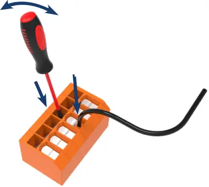
WIRE INSTALLATION
- Insert screwdriver and push wire locking mechanism open
- Insert wire
- Remove screwdriver
- Due to possible significant interference in industrial installations, appropriate measures assuring the correct operation of the unit must be applied.
- The unit is not equipped with an internal fuse or power supply circuit breaker.
- For this reason, an external time-delay cut-out fuse with a small nominal current value must be used (recommended bipolar, max. 2A) and a power supply circuit breaker located near the unit.
- In the case of using a monopolar fuse, it must be mounted on the phase cable.
Programming 4-20mA Input
![]()
![]() Calculating 4-20mA Input
Calculating 4-20mA Input
| SENSOR TYPE | 20mA Set Point |
| Submersible | Range of sensor / Specific Gravity = 20mA |
| Ultrasonic | Tank Height |
| Radar | Tank Height |
Programming Relays![]() RS485 Modbus Programming
RS485 Modbus Programming
THE MODBUS PRO TOCOL HANDLING
- Transmission parameters: 1 start bit, 8 data bits, 1 or 2 stop bits (2 bits are sent, 1 and 2 bits are accepted when received), no parity control
- Baud rate: selectable from 1200 to 115200 bits/second
- Transmission protocol: MODBUS RTU compatible
- The device parameters and display value are available via the RS-485 interface, as HOLDING-type registers (numeric values are given in U2 code) of Modbus RTU protocol. The registers (or groups of the registers) can be read by the 03h function and written by 06h (single registers) or 10h (group of the registers) according to Modbus RTU specification. Maximum group size for 03h and 10h functions can not exceed 16 registers (for single frame).
- The device interprets the broadcast messages but then does not send the answers.
LIST OF REGISTERS
| Register | Write | Range | Register description |
| 01h | No | -999 ÷ 9999 | Measurement value (no decimal point) |
| 02h | No | 0h, A0h, 60h | The status of the current measurement; 0h – data valid; A0h – top border of the measurement range is exceeded; 60h – bottom border of the measurement range is exceeded; |
| 03h | Yes | 0 ÷ 3 | “Pnt ” parameter in the “InPt” menu (decimal point position) 0 – “ 0”; 1 – “ 0.0”; 2 – “ 0.00”; 3 – “0.000” |
| 04h | Yes | see descr. | State of the relays and alarm LED (binary format) (1 – on, 0 – off): 00000000 000e00ba a – relay R1; b – relay R2; e – alarm LED;
If written, only a, and b bits are important (others are ignored) these bits allow the user to control the relays via the RS-485 interface |
| 05h1 | Yes | 0h ÷ 1800h | State of active current output, expressed in 1/256 mA units – it means that the high byte expresses the integer part and the low byte fractional part of the desired output current. |
| Yes | 2CCh÷1800h | State of passive current output, expressed in 1/256 mA units – it means that the high byte expresses the integer part and the low byte fractional part of the desired output current. | |
| Yes | 0h ÷ 1600h | State of active voltage output, expressed in 1/512 V units – it means that high byte express integer part, and low byte fractional part of desired output voltage. | |
| 06h | No | -999 ÷ 9999 | Peak (drop) value (no decimal point) |
| 10h | Yes | 0 ÷ 5 | “tyPE” parameter in the “InPt” menu (nominal input range). 0 – 0-20 mA range; 1 – 4-20 mA range; 2 – 0-10 V range; 3 – 2-10 V range; 4 – 0-5 V range; 5 – 1-5 V range |
| 11h | Yes | 0 ÷ 5 | “CHAr” parameter in the “InPt” menu (characteristic type) 0 – linear; 1 – square; 2 – square root; 3 – user-defined; 4 – volume characteristics of a cylindrical tank in the vertical position; 5 – volume characteristics of a cylindrical tank in the horizontal position |
| 12h | Yes | 0 ÷ 5 | “FiLt” parameter in the “InPt” menu (measurement filtering rate) |
RS485 Modbus Programming
| Register | Write | Range | Register description |
| 13h | Yes | 0 ÷ 3 | “Pnt ”parameter in “InPt” menu (the copy of 03h register, decimal point position) 0 – “ 0”; 1 – “ 0.0”; 2 – “ 0.00”; 3 – “0.000” |
| 14h | Yes | -999 ÷ 9999 | “Lo C” parameter in “InPt” menu, no decimal point included |
| 15h | Yes | -999 ÷ 9999 | “Hi C” parameter in the “InPt” menu, no decimal point included |
| 16h | Yes | 0 ÷ 999 | “Lo r” parameter in the “InPt” menu, in 0.1% |
| 17h | Yes | 0 ÷ 199 | “Hi r” parameter in the “InPt” menu, in 0.1% |
| 19h | Yes | 0 ÷ 9999 | “t h1” parameter in the “InPt” menu, no decimal point included |
| 1Ah | Yes | 0 ÷ 9999 | “t h2” parameter in the “InPt” menu, no decimal point included |
| 1Bh | Yes | 0 ÷ 9999 | “t h3” parameter in the “InPt” menu, no decimal point included |
| 1Ch | Yes | 0 ÷ 9999 | “t d” parameter in the “InPt” menu, no decimal point included |
| 1Dh | Yes | 0 ÷ 9999 | “t Sn” parameter in the “InPt” menu, no decimal point included |
| 1Eh | Yes | 0 ÷ 9999 | “t Sh” parameter in the “InPt” menu, no decimal point included |
| 20h2 | Yes | 0 ÷ 199 | Device address |
| 21h | No | 21F0h | Device identification code (ID) |
| 22h3 | Yes | 0 ÷ 7 | “bAud” parameter in “rS” menu (baud rate);
0 – 1200 baud; 1 – 2400 baud; 2 – 4800 baud; 3 – 9600 baud; 4 – 19200 baud; 5 – 38400 baud; 6 – 57600 baud; 7 – 115200 baud |
| 23h4 | Yes | 0 ÷ 1 | “mbAc” parameter in “rS” menu (permission to write registers via RS-485 interface); 0 – write denied ; 1 – write allowed |
| 24h | Yes | see descr. | Parameters of “SECU” menu (binary format (0 – „oFF”, 1 – „on”): bit 0 – “A r1” parameter; bit 1 – “A r2” parameter |
| 25h | Yes | 0 ÷ 5 | “rESP” parameter in “rS” menu (additional response delay);
0 – no additional delay; 1 – ”10c” option; 2 – ”20c” option; 3 – ”50c” option; 4 – ”100c” option; 5 – ”200c” option; |
| 27h | Yes | 0 ÷ 99 | “mbtO” parameter in “rS” menu (maximum delay between received frames); 0 – no delay checking;
1 ÷ 99 – maximum delay expressed in seconds |
| 2Dh | Yes | 1 ÷ 8 | “Bri” parameter (display brightness);
1 – the lowest brightness; 8 – the highest brightness |
| 2Fh | Yes | 0 ÷ 1 | “Edit” parameter (numerical parameters edit mode);
0 – „dig” mode; 1 – „SLid” mode |
| 30h | Yes | -999 ÷ 9999 | “SEtP” parameter in “rEL1” menu, no decimal point included |
| 31h | Yes | -999 ÷ 999 | “HySt” parameter in “rEL1” menu, no decimal point included |
| 32h | Yes | 0 ÷ 5 | “modE” parameter in the “rEL1” menu:
0 – “no” mode; 1 – “on” mode; 2 – “of” mode; 3 – “in” mode; 4 – “out” mode; 5 – “mod” mode |
| 33h | Yes | 0 ÷ 999 | The “t on” parameter in the “rEL1” menu, expressed in tenth of seconds or tenth of minutes depends on the “unit” parameter – register no. 35h) |
RS485 Modbus Programming
| Register | Write | Range | Register description |
| 34h | Yes | 0 ÷ 999 | The “toFF” parameter in the “rEL1” menu, expressed in a tenth of seconds or tenth of minutes depends on the “unit” parameter – register no. 35h) |
| 35h | Yes | 0 ÷ 1 | “unit” parameter in the “rEL1” menu:
0 – seconds; 1 – minutes |
| 36h | Yes | 0 ÷ 2 | “AL” parameter in the “rEL1” menu: 0 – no changes; 1 – on; 2 – off |
| 37h | Yes | -999 ÷ 9999 | “SEt2” parameter in “rEL1” menu, no decimal point included |
| 38h | Yes | -999 ÷ 9999 | “SEtP” parameter in “rEL2” menu, no decimal point included |
| 39h | Yes | -999 ÷ 999 | “HySt” parameter in “rEL2” menu, no decimal point included |
|
3Ah |
Yes |
0 ÷ 5 |
“modE” parameter in the “rEL2” menu:
0 – “no” mode; 1 – “on” mode; 2 – “of” mode; 3 – “in” mode; 4 – “out” mode; 5 – “mode” mode |
| 3Bh | Yes | 0 ÷ 999 | “t on” parameter in the “rEL2” menu, expressed in a tenth of seconds or tenth of minutes depending on the “unit” parameter – register no. 3Dh) |
| 3Ch | Yes | 0 ÷ 999 | “toFF” parameter in the “rEL2” menu, expressed in the tenth of seconds or tenth of minutes depending on the “unit” parameter – register no. 3Dh) |
| 3Dh | Yes | 0 ÷ 1 | “unit” parameter in the “rEL2” menu:
0 – seconds; 1 – minutes |
| 3Eh | Yes | 0 ÷ 2 | “AL” parameter in the “rEL2” menu: 0 – no changes; 1 – on; 2 – off |
| 3Fh | Yes | -999 ÷ 9999 | “SEt2” parameter in “rEL2” menu, no decimal point included |
| 50h | Yes | 0 ÷ 1 | “modE” parameter in “HOLd” menu (type of detected changes):
0 – peaks; 1 – drops |
| 51h | Yes | 0 ÷ 9999 | “PEA” parameter in “HOLd” menu (minimum detectable change, no decimal point included) |
| 52h | Yes | 0 ÷ 199 | “Time” parameter in the “HOLd” menu, maximum peaks’ (or drops’) display time expressed in seconds |
| 53h | Yes | 0 ÷ 1 | “HdiS” parameter in the “HOLd” menu:
0 – “rEAL” mode; 1 – “HOLd” mode |
| 54h | Yes | 0 ÷ 1 | “H r1” parameter in “HOLd” menu :
0 – “rEAL” mode; 1 – “HOLd” mode |
| 55h | Yes | 0 ÷ 1 | “H r2” parameter in “HOLd” menu:
0 – “rEAL” mode; 1 – “HOLd” mode |
| 58h1 | Yes | 0 ÷ 1 | “HOut” parameter in the “HOLd” menu:
0 – “rEAL” mode; 1 – “HOLd” mode |
| 70h5 | Yes | -999 ÷ 1999 | The value of the „X” coordinate of point no. 1 of the user-defined characteristic, expressed in 0.1% |
| 71h5 | Yes | -999 ÷ 9999 | The value of the „Y” coordinate of point no. 1 of the user-defined characteristic, no decimal point included |
| 72h5 ÷ 95h5 | Further pairs of „X” – „Y” coordinates of points no. 2 ÷ 19 of the user-defined characteristic | ||
RS485 Modbus Programming
| Register | Write | Range | Register description |
| 96h5 | Yes | -999 ÷ 1999 | The value of the „X” coordinate of point no. 20 of the user-defined characteristics, expressed in 0.1% |
| 97h5 | Yes | -999 ÷ 9999 | The value of the „Y” coordinate of point no. 20 of the user-defined characteristics, no decimal point included |
| A0h1 | Yes | 0 ÷ 3 | “Omod” parameter in the “OUtP” menu (active current output mode)
0 – current output disabled; 1 – current output enabled with 4÷20mA mode; 2 – current output enabled with 0÷20mA mode; 3 – current output controlled via RS-485 interface |
| Yes | 0 ÷ 2 | “Omod” parameter in “OUtP” menu (passive current output mode) 0 – current output disabled; 1 – current output enabled with 4÷20mA mode; 2 – current output controlled via RS-485 interface | |
| Yes | 0 ÷ 5 | “Omod” parameter in “OUtP” menu (active voltage output mode) 0 – voltage output disabled; 1 – voltage output enabled with 0÷5V mode; 2 – voltage output enabled with 1÷5V mode; 3 – voltage output enabled with 0÷10V mode; 4 – voltage output enabled with 2÷10V mode; 5 – voltage output controlled via RS-485 interface | |
| A1h1 | Yes | -999 ÷ 9999 | “OUtL” parameter in “OUtP” menu, no decimal point included |
| A2h1 | Yes | -999 ÷ 9999 | “OUtH” parameter in the “OUtP” menu, no decimal point included |
| A3h1 | Yes | 0 ÷ 999 | “Lo r” parameter in the “OUtP” menu, for active current output and active voltage output, expressed in 0.1% |
| Yes | 0 ÷ 299 | “Lo r” parameter in the “OUtP” menu for passive current output, expressed in 0.1% | |
| A4h1 | Yes | 0 ÷ 199 | “Hi r” parameter in the “OUtP” menu for active and passive current output, expressed in 0.1% |
| Yes | 0 ÷ 99 | “Hi r” parameter in the “OUtP” menu for active voltage output, expressed in 0.1% | |
| A5h1 | Yes | 0 ÷ 3 | “AL” parameter in the “OUtP” menu (active current output value on critical exception): 0 – no change; 1 – 22.1 mA; 2 – 3.4 mA; 3 – 0 mA |
| Yes | 0 ÷ 2 | “AL” parameter in the “OUtP” menu (passive current output value on critical exception): 0 – no change; 1 – 22.1 mA; 2 – 3.4 mA | |
| Yes | 0 ÷ 5 | “AL” parameter in the “OUtP” menu (active voltage output value on critical exception): 0 – no change; 1 – 11 V; 2 – 5.5; 3 – 1.2 V; 4 – 0.6 V; 5 – 0 V |
- these registers are active only if the device is equipped with current or voltage output
- after writing to register no 20h the device responds with an “old” address in the message.
- after writing to register no 22h the device responds with the new baud rate.
- the value of the “mbAc” parameter is also connected to write to this register, so it is possible to block writes, but impossible to unblock writes via the RS-485 interface, The unblocking of the writes is possible from the menu level only.
- the pairs of „X -Y” coordinates may be defined for any free point. The pair is “free” (it means that a particular point is not defined) if the „X” coordinate of this point is equal to 8000h. After writing both X and Y coordinates the point is defined and used in the calculation of the result. The coordinates of any point can be changed at any time.
TRANSMISSION ERRORS DESCRIPTION
- If an error occurs while writing or reading of single register, then the device sends an error code according to Modbus RTU specifications (example message no 1).
Error codes:
- 01h – illegal function (only functions 03h, 06h and 10h are available),
- 02h – illegal register address
- 03h – illegal data value
- 08h – no write permission ( see: “mbAc” parameter)
- A0h – exceed of upper border of input range
- 60h – exceed of lower border of input range
- A0h and 60h codes can appear only during reg. 01h is reading by 03h function (read of a single register).
EXAMPLES OF QUERY/ANSWER FRAMES
- Examples apply for device with address 1. All values are represent hexadecimal.
Field description:
- ADDR Device address on Modbus network
- FUNC Function code
- REG H, L Starting address (address of the first register to read/write, Hi and Lo byte)
- COUNT H, L No. of registers to read/write (Hi and Lo byte)
- BYTE C Data byte count in answer frame
- DATA H, L Data byte (Hi and Lo byte)
- CRC L, H CRC error check (Hi and Lo byte)
Read of the displayed value (measurement), SRP-N118 device address = 01h:
| ADDR | FUNC | REG H, L | COUNT H, L | CRC L, H | |||
| 01 | 03 | 00 | 01 | 00 | 01 | D5 | CA |
a) The answer (we assume that the measured result is not out of range)
| ADDR | FUNC | BYTE C | DATA H, L | CRC L, H | ||
| 01 | 03 | 02 | 00 | F | F8 | 04 |
- DATA HL – displayed value = 255, no decimal point.
- Decimal point position can be read from reg. 03h
b) The answer (if an error occurs).
| ADDR | FUNC | ERROR | CRC L, H | |
| 01 | 83 | 60 | 41 | 18 |
ERROR – error code = 60h, the bottom border of the measurement range is exceeded
Read of device ID code
| ADDR | FUNC | REG H, L | COUNT H, L | CRC L, H | |||
| 01 | 03 | 00 | 21 | 00 | 01 | D4 | 00 |
The answer:
| ADDR | FUNC | BYTE C | DATA H, L | CRC L, H | ||
| 01 | 03 | 02 | 21 | F0 | A0 | 50 |
DATA – identification code (21F0h)
Change of the device address from 1 to 2 (write to reg. 20h)
| ADDR | FUNC | REG H, L | DATA H, L | CRC L, H | |||
| 01 | 06 | 00 | 20 | 00 | 02 | 09 | C1 |
- DATA H – 0
- DATA L – new device address (2)
The answer (the same as the message):
| ADDR | FUNC | REG H, L | DATA H, L | CRC L, H | |||
| 01 | 06 | 00 | 20 | 00 | 02 | 09 | C1 |
Change of baud rate of all devices connected to the net (BROADCAST message).
| ADDR | FUNC | REG H, L | COUNT H, L | CRC L, H | |||
| 00 | 06 | 00 | 22 | 00 | 04 | 29 | D2 |
- DATA H – 0
- DATA L – 4, new baud rate 19200 baud
- The device does not reply to BROADCAST-type messages.
Read registers 1, 2, and 3 in one message (example of reading many registries in one frame):
| ADDR | FUNC | REG H, L | COUNT H, L | CRC L, H | |||
| 01 | 03 | 00 | 01 | 00 | 03 | 54 | 0B |
COUNT L – the count of being read registers (max.16)
The answer:
| ADDR | FUNC | BYTE C | DATA H1,L1 | DATA H2,L2 | DATA H3,L3 | CRC L, H | ||||
| 01 | 03 | 06 | 00 | 0A | 00 | 00 | 00 | 01 | 78 | B4 |
- DATA H1, L1 – reg. 01h (10 – displayed value ”1.0”),
- DATA H2, L2 – reg. 02h (0 – no errors),
- DATA H3, L3 – reg. 03h (1 – decimal point position ” 0.0”).
- There is no full implementation of the Modbus Protocol in the device. The functions presented above are available only.
DEFAULT AND USERS SETTINGS LIST
| Parameter | Description | Default value | User’s value | Dec. page |
| Parameters of relay R1 operation (“rEL1” menu) | ||||
| SEtP | Relay R1 threshold | 20.0 | 29 | |
| SEt2 | Relay R1 second threshold | 40.0 | 29 | |
| HYSt | Hysteresis of relay R1 | 0.0 | 29 | |
| modE | The operation mode of relay R1 | on | 29 | |
| t on | Turn on a delay of relay R1 | 0.0 | 30 | |
| toFF | Turn off the delay of relay R1 | 0.0 | 30 | |
| unit | Unit of “t on”, and “toFF” parameters of relay R1 | SEC | 30 | |
| AL | Reaction to critical situation of relay R1 | oFF | 30 | |
| Parameters of relay R2 operation (“rEL2” menu) | ||||
| SEtP | Relay R2 threshold | 40.0 | 29 | |
| SEt2 | Relay R2 second threshold | 60.0 | 29 | |
| HYSt | Hysteresis of relay R2 | 0.0 | 29 | |
| modE | The operation mode of relay R2 | on | 29 | |
| t on | Turn on the delay of relay R2 | 0.0 | 30 | |
| toFF | Turn off the delay of relay R2 | 0.0 | 30 | |
| unit | Unit of “t on”, and “toFF” parameters of relay R2 | SEC | 30 | |
| AL | Reaction to critical situation of relay R2 | oFF | 30 | |
| Configuration of measurement input (“input” menu) | ||||
| tYPE | Input mode | „4-20” | 31 | |
| CHAr | Conversion characteristic mode | Lin | 31 | |
| FiLt | Filtering ratio | 0 | 31 | |
| Pnt | Decimal point position | 0.0 | 31 | |
| Lo C | Minimum displayed value (for nominal range) | 000.0 | 32 | |
| Hi C | Maximum displayed value (for nominal range) | 100.0 | 32 | |
| t h1 | Height (length) first part of the tank | 00.00 | 32 | |
| t h2 | Height (length) second part of the tank | 00.00 | 32 | |
| t h3 | Height (length) third part of the tank | 00.00 | 32 | |
| t d | Tank diameter | 00.01 | 32 | |
| t Sn | Distance between sensor and bottom of the tank | 00.00 | 32 | |
| t Sh | Height of the sensor | 20.00 | 32 | |
| Lo r | Extension of the bottom of the nominal input range | 5.0 (%) | 35 | |
| Parameter | Description | Default value | User’s value | Dec. page |
| Hi r | Extension of the top of the nominal input range | 5.0 (%) | 35 | |
| Current output configuration (“OUtP” menu) | ||||
| Omod | Current output mode | „4-20” (mA) | 37 | |
| OUtL | Display value for 4 mA current output | 0.0 | 37 | |
| OUtH | Display value for 20 mA current output | 100.0 | 37 | |
| Lo r | Extension of the bottom of the nominal output range | 5.0 (%) | 38 | |
| Hi r | Extension of the top of the nominal output range | 5.0 (%) | 38 | |
| AL | Current output value on critical exception | 22.1 (mA) | 38 | |
| Display Parameters | ||||
| bri | Display brightness | bri6 | 38 | |
| Configuration of peaks detection function (“HOLd” menu) | ||||
| modE | Kind of detected changes | norm | 39 | |
| PEA | Minimum detected change | 0.0 | 39 | |
| Time | Maximum time of peak displaying | 0.0 | 39 | |
| HdiS | The type of displayed value | HOLd | 39 | |
| H r1 | Source of relay R1, and LED R1 control | rEAL | 39 | |
| H r2 | Source of relay R2, and LED R2 control | rEAL | 39 | |
| HOut | Source of current output control | rEAL | 39 | |
| Settings of access to the configuration parameters (“SECu” menu) | ||||
| A r1 | Permission to changes of relay R1 threshold without the user password knowledge | on | 39 | |
| A r2 | Permission to changes of relay R2 threshold without the user password knowledge | on | 39 | |
| RS 485 interface configuration (menu “rS”) | ||||
| Address | Device address | 0 | 40 | |
| bAud | Baud rate | 9.6 | 40 | |
| MBA | Permission to changes of configuration registers | on | 40 | |
| MB to | Maximum delay between received messages | 0 | 40 | |
| rESP | Additional delay of answer transmission | Std | 40 | |
| Configuration of numerical parameters edition | ||||
| Edit | Numerical parameters edit mode | dig | 41 | |
24-0222 © Icon Process Controls Ltd.
Documents / Resources
 |
ICON PROCESS CONTROLS TVL Series Tank Level Display and Controller [pdf] Owner's Manual TVL Series Tank Level Display and Controller, TVL Series, Tank Level Display and Controller, Display and Controller, Controller |

