GOODWE EZLOGGER3C Smart Data Logger
Copyright ©GoodWe Technologies Co., Ltd., 2023. All rights reserved
No part of this document can be reproduced or transmitted to the public platform in any form or by any means without the prior written authorization of GoodWe.
Trademarks
![]() and other GoodWe trademarks are trademarks of GoodWe Company. All other trademarks or registered trademarks mentioned in this document are owned by GoodWe Company.
and other GoodWe trademarks are trademarks of GoodWe Company. All other trademarks or registered trademarks mentioned in this document are owned by GoodWe Company.
NOTICE
The information in this document is subject to change due to product updates or other reasons. This document cannot replace the product labels or the safety precautions unless otherwise specified. All descriptions in the document are for guidance only.
About This Manual
This document describes the product information, installation, electrical connection, commissioning, troubleshooting, and maintenance. Read through this document before installing and operating the product. All the installers and users have to be familiar with the product features, functions, and safety precautions. This document is subject to update without notice. For more product details and latest documents, please visit https://en.goodwe.com.
Applicable Model
This document applies to the Smart DataLogger: EzLogger3000C (EzLogger for short).
Target Audience
This document applies to trained and knowledgeable technical professionals only. The technical personnel has to be familiar with the product, local standards, and electric systems.
Symbol Definition
Different levels of warning messages in this document are defined as follows:

Updates
The latest document contains all the updates made in earlier issues.
V1.0 6/10/2023
First Issue
Safety Precaution
Notice
- The equipment is designed and tested strictly in compliance with related safety rules. Read and follow all the safety instructions and cautions before any operations. Improper operation might cause personal injury or property damage as the equipments are electrical equipment.
- Changes or modifications not expressly approved by the party responsible for compliance could void the user’s authority to operate the equipment
General Safety
Notice
- The information in this document is subject to change due to product updates or other reasons. This document cannot replace the product labels or the safety precaution unless otherwise specified. All descriptions in the document are for guidance only.
- Before installations, read through this document to learn about the product and the precautions.
- All installations should be performed by trained and knowledgeable technicians who are familiar with local standards and safety regulations.
- Strictly follow the installation, operation, and configuration instructions in this document. The manufacturer shall not be liable for equipment damage or personal injury if you do not follow the instructions. For more warranty details, visit https://www.goodwe.com/support-service/warranty-related.
Grounding Safety
Danger
When installing the equipment, the grounding cable must be installed first; when removing the equipment, the grounding cable must be removed last.
Warning
- Connect a PE cable to the nearest grounding point of the equipment.
- Before operation, make sure the device is reliably grounded.
Personal Safety
Danger
- Use insulating tools and wear personal protective equipment (PPE) when operating the equipment to ensure personal safety.
- Do not touch the equipment when it is short-circuited. Keep away from the equipment, and turn off the power immediately.
- Before wiring, disconnect all upstream switches to ensure the device is not powered on.
Equipment Safety
Danger
Make sure the installation place is solid enough to bear the equipment weight before installation.
Warning
- Use appropriate tools for proper installation, maintenance, etc.
- Observe local standards and safety regulations when operating the equipment.
- Unauthorized disassembly or modification may cause damage to the equipment, which is not covered within the warranty scope.
Definition of Warning Labels
Danger
- All labels and warning marks must be clear and distinct after the installation. Do not block, alter, or damage any label.
- Warning labels on the equipment are as follows.

Personnel Requirements
Notice
- Personnel who install or maintain the equipment must be strictly trained, learn about safety precautions and correct operations.
- Only qualified professionals or trained personnel are allowed to install, operate, maintain, and replace the equipment or parts.
EU Declaration of Conformity
The equipment without wireless communication modules sold in the European market meets the requirements of the following directives:
- Electromagnetic compatibility Directive 2014/30/EU (EMC)
- Electrical Apparatus Low Voltage Directive 2014/35/EU (LVD)
- Restrictions of Hazardous Substances Directive 2011/65/EU and (EU) 2015/863 (RoHS)
- Waste Electrical and Electronic Equipment 2012/19/EU
- Registration, Evaluation, Authorization and Restriction of Chemicals (EC) No 1907/2006 (REACH) You can download the EU Declaration of Conformity on: https://en.goodwe.com.
Federal Communications Commission (FCC) Interference Statement
This equipment has been tested and found to comply with the limits for a Class B digital device, pursuant to Part 15 of the FCC Rules.
These limits are designed to provide reasonable protection against harmful interference in a residential installation. This equipment generates, uses and can radiate radio frequency energy and, if not installed and used in accordance with the instructions, may cause harmful interference to radio communications.
However, there is no guarantee that interference will not occur in a particular installation. If this equipment does cause harmful interference to radio or television reception, which can be determined by turning the equipment off and on, the user is encouraged to try to correct the interference by one of the following measures:
- Reorient or relocate the receiving antenna.
- Increase the separation between the equipment and receiver.
- Connect the equipment into an outlet on a circuit different from that to which the receiver is connected.
- Consult the dealer or an experienced radio/TV technician for help.
This device complies with Part 15 of the FCC Rules. Operation is subject to the following two conditions: This device may not cause harmful interference. this device must accept any interference received, including interference that may cause undesired operation. FCC Caution: Any changes or modifications not expressly approved by the party responsible for compliance could void the user’s authority to operate this equipment.
RF exposure warning
This equipment complies with FCC radiation exposure limits set forth for an uncontrolled environment.
This equipment must be installed and operated in accordance with provided instructions and the antenna(s) used for this transmitter must be installed to provide a separation distance of at least 20 cm from all persons and must not be collocated or operating in conjunction with any other antenna or transmitter.
Product Introduction
Functions
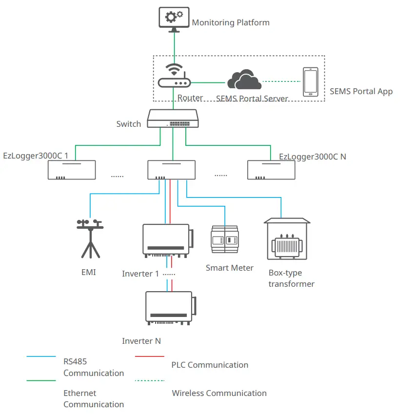
EzLogger is an exclusive equipment to connect with the monitoring platform in PV power generation system. It integrates the ports to connect with the inverter, the environmental monitoring instrument (EMI), the smart meter and other devices. It owns the functionalities of data logging, log storage, centralized monitoring and maintenance in PV power generation system.
Networking
EzLogger is applicable to the PV power generation system:
- Via RS485 communication to connect: RS485 devices such as the inverter, the smart meter, and EMI;
- Via Ethernet communication to connect: the router, the switch, PC and power plant monitoring system;
- Via PLC communication to connect: the inverters with PLC functionality.
Networking of Single EzLogger3000C

- A single RS485 communication channel in EzLogger3000C can support a maximum of 20 inverters’ connections.
- A single PLC communication channel in EzLogger3000C can support a maximum of 60 inverters’ connections.
Networking of Multiple EzLogger3000Cs
Parts and Dimensions
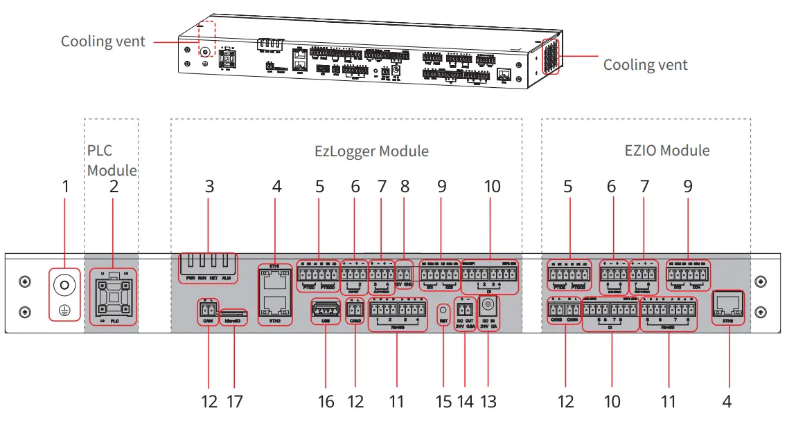
| No. | Silkscreen | Description |
| 1 | Grounding point | |
| 2 | PLC | Port connected for PLC communication |
| 3 | Indicator | Indicate the equipment’s working status. |
| 4 | ETH1-3 | Port connected with the Ethernet cable. |
| 5 | PT100 PT1000 | Port connected with the thermo sensor. |
| 6 | AI_0-12V AI_0-100mA | AI signal input port: 0-12V or 0-100mA |
| 7 | AI_0/4-20mA | AI signal input port: 4-20mA |
| 8 | 12V GND | 12V power output port |
| 9 | DO1-4 | DO signal output port |
| 10 | DI | DI signal input port, to connect to Passive and Active contact signal. |
| 11 | RS485 | RS485 communication port |
| 12 | CAN1-4 | CAN communication port |
| 13 | DC IN | 24V DC power input port |
| 14 | DC OUT | 24V DC power output port |
| 15 | RST | Reset button Long press >5S: EzLogger reboots and restores factory default network settings; short press 1~3S: EzLogger reboots |
| 16 | USB | U disk connection port for system software version update |
| 17 | MicroSD | MmiacirnotSeDnacnacrde liongteirnfafocremtoatsitoonre EzLogger operation log, operation log and |
Indicators
| Indicator | Definition | Description |
| PWR | Power Status Indicator | Green off: the power supply of EzLogger is abnormal. |
| Green continues on: the power supply of EzLogger is normal. | ||
| RUN | Operating Indicator | Green flashes slowly: EzLogger runs normally. |
|
NET |
NInedtiwcaotrokring Status | Green flashes twice: EzLogger is not connected to the router. |
| Gnoreteton tflhaesheextseqrnualrtnice:twEzoLrokgsgeerrveisr.properly connected to the router, but | ||
| Green continues on: The communication of EzLogger is normal. | ||
| ALM | Reserved | |
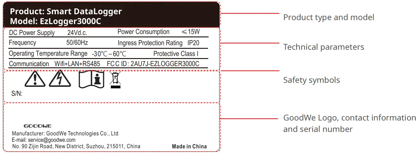
Nameplate
The nameplate is for reference only.
Check and Storage
Check before Receiving
Check the following items before receiving the product.
- Check the outer packing box for damage, such as holes, cracks, deformation, and others signs of equipment damage. Do not unpack the package and contact the supplier as soon as possible if any damage is found.
- Check the product model. If the product model is not what you requested, do not unpack the product and contact the supplier.
- Check the deliverables for correct model, complete contents, and intact appearance. Contact the supplier as soon as possible if any damage is found.
Storage
If the equipment is not to be installed or used immediately, please ensure that the storage environment meets the following requirements:
- Do not unpack the outer package or throw the desiccant away.
- Store the equipment in a clean place. Make sure the temperature and humidity are appropriate and no condensation.
- If the equipment has been long term stored, it should be checked by professionals before being put into use.
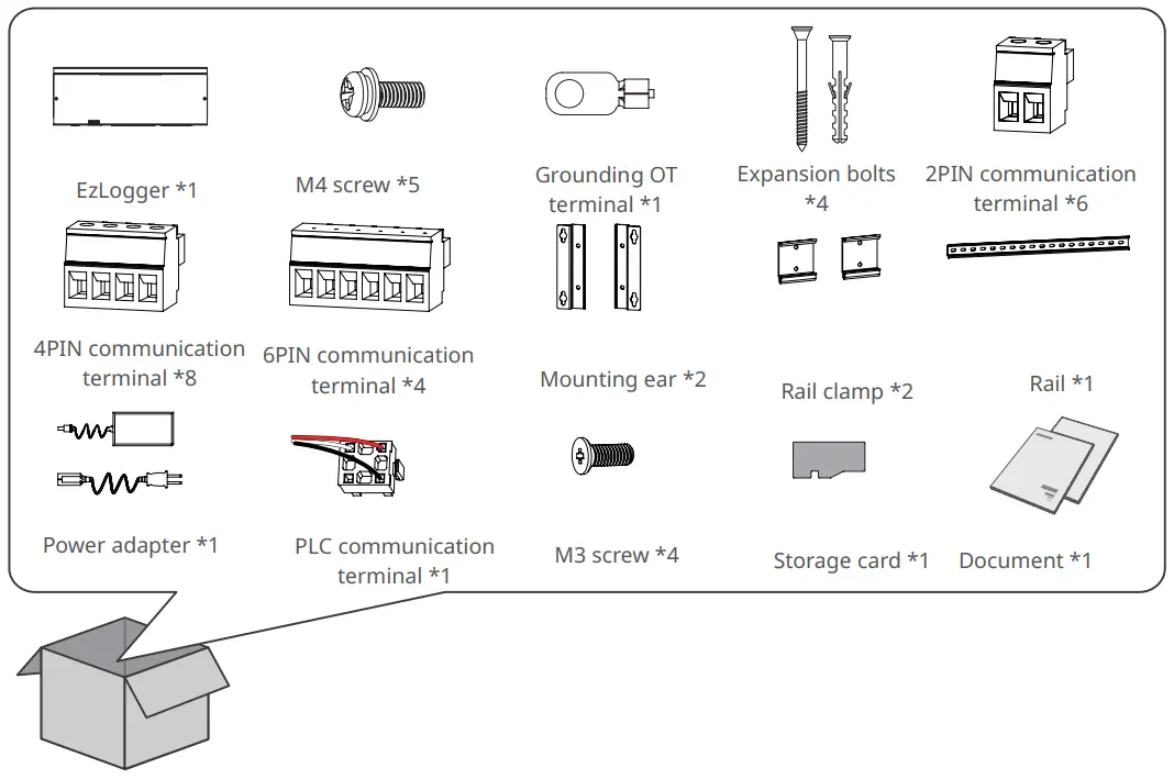
Deliverables
Notice
Use the delivered terminals and screws. The manufacturer shall not be liable for the equipment damage if other connectors or terminals are used.
Installation
Installation Requirements
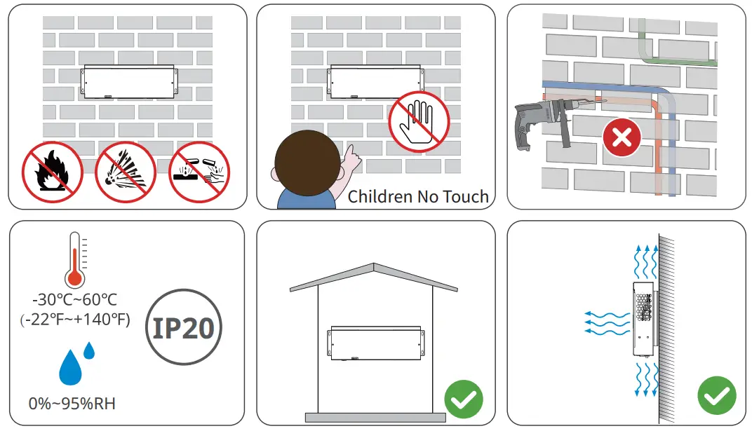
Installation Environment Requirements
- Do not install the equipment in a place near flammable, explosive, or corrosive materials.
- Install the equipment on a surface that is solid enough to bear its weight.
- The place to install the equipment shall be well-ventilated for heat radiation and large enough for operations.
- The equipment with a high ingress protection rating can be installed outdoors.The temperature and humidity at the installation site should be within the appropriate range.
- Do not install the equipment in a place that is easy to touch, especially within children’s reach.
- Install the equipment at a height that is convenient for operation and maintenance, electrical connections, and checking indicators and labels.
- Install the equipment away from electromagnetic interference.
Mounting Support Requirements
- The mounting support shall be nonflammable and fireproof.
- Install the equipment on a surface that is solid enough to bear its weight.
Installation Tool Requirements
The following tools are recommended when installing the equipment. Use other auxiliary tools on site if necessary.

EzLogger Installation
Wall-Mounting
Notice
- Avoid the water pipes and cables buried in the wall when drilling holes.
- Wear goggles and a dust mask to prevent the dust from being inhaled or contacting eyes when drilling holes.
Step 1 Install the mounting plate on EzLogger with M4 screws.
Step 2 Put the EzLogger on the wall horizontally and mark positions for drilling holes.
Step 3 Drill holes to a depth of 30mm with the hammer drill. The diameter of the drill bit should be 8mm. Install the exposition bolts.
Step 4 Tighten the expansion bolts.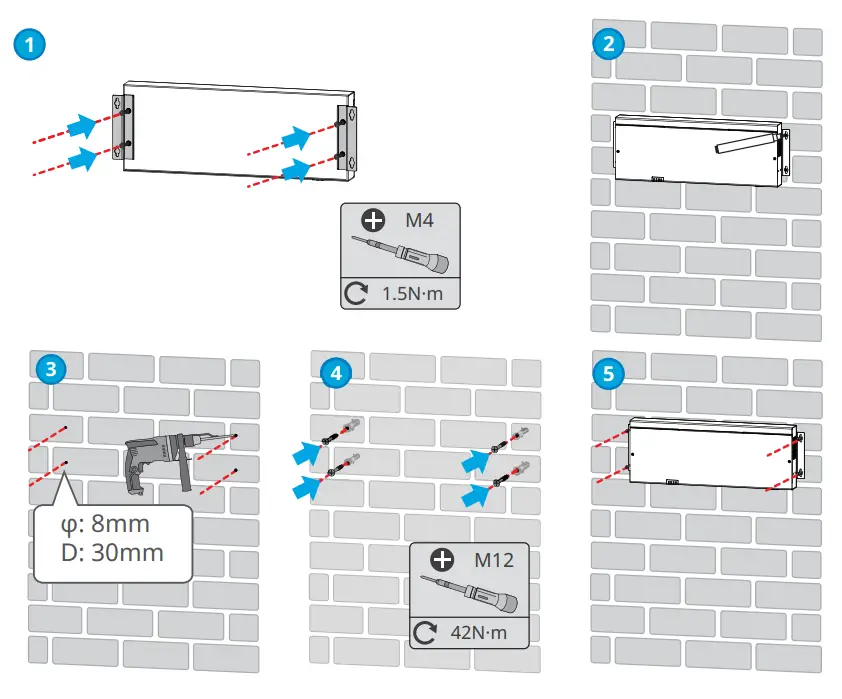
Rail-Mounting
Notice
- Install the mounting plate of the rail on the EzLogger for rail mounting.
- The rail shall be installed on a sturdy and stable support.
Step 1 Install the mounting plate on EzLogger with M3 screws.
Step 2 Install the EzLogger on the support with expansion bolts.
Step 3 Install the EzLogger onto the rail.
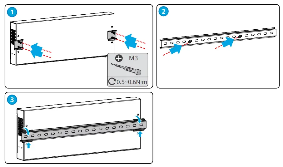
Table-Mounting
The EzLogger supports desktop installation.
Notice
- Install the EzLogger on a flat desktop to prevent it from sliding and getting damaged.
- Do not place the EzLogger in locations where cables can be easily accessed, as this may result in signal interrup-tion.
Electrical Connection
Safety Precaution
Danger
- Before wiring, disconnect all upstream switches of the EzLogger to ensure it is not powered on. Do not work with power on. Otherwise, an electric shock may occur.
- All operations, cables and parts specification during the electrical connection shall be in compliance with local laws and regulations.
- If the tension is too large, the cable may be poorly connected. Reserve a certain length of the cable before connecting it to the wiring port of the EzLogger.
Notice
- Wear PPE like safety shoes, safety gloves, and insulating gloves during electrical connections.
- All electrical connections should be performed by qualified professionals.
- Cable colors in this document are for reference only. The cable specifications shall meet local laws and regulations.
| No. | Cable | Silkscreen | Specification |
| 1 | PE cable | • Outdoor copper cable
• Conductor cross-sectional area: 6mm2~10mm2 (10AWG~8AWG) |
|
| 2 | DC output cable
(12V/24V) |
DC OUT / 12V
GND |
• Outdoor copper cable
• Conductor cross-sectional area: 0.12mm2~1.5mm2 (28AWG~16AWG) |
| 3 | DO signal cable | DO 1-4 | • Outdoor copper cable
• Conductor cross-sectional area: 0.2mm2~1.5mm2 (24AWG~16AWG) |
|
4 |
RS485
communication cable |
RS485 1-8 |
• Outdoor copper cable • Conductor cross-sectional area: 0.08mm2~1.5mm2 (28AWG~16AWG) |
| 5 | DI signal cable | DI | |
| 6 | AI signal cable | AI | |
| 7 | PT signal cable | PT100/PT1000 | |
| 8 | CAN signal
cable |
CAN 1-4 | |
| 9 | Ethernet cable | ETH 1-3 | • CAT 5E or higher specifications
• Shielded connector |
| 10 | Three-phase AC
cable |
PLC | • Delivered with the equipment.
• Cable length: 1500mm (59.06in.) |
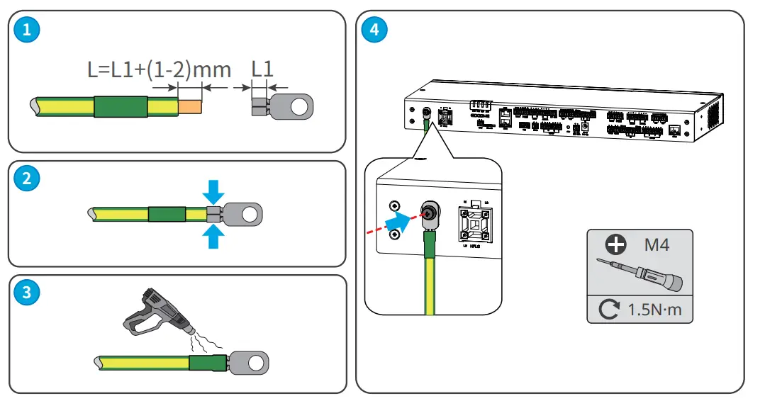
Connecting the PE Cable
Warning
- Connect the grounding points of the equipment nearer.
- Before operation, make sure the equipment is reliably grounded.
- To improve the corrosion resistance of the terminal, it is recommended to apply silica gel or paint on the grounding terminal after installing the PE cable.
Notice
- Use the OT grounding terminals and screws delivered.
- Prepare the PE cable.
Step 1 Strip an appropriate length of insulation from the cable.
Step 2 Crimp the cables to the grounding OT terminals.
Step 3 Wrap the crimping area with insulation tube.
Step 4 Secure the PE cable to the grounding point of the EzLogger with the M4 screw.
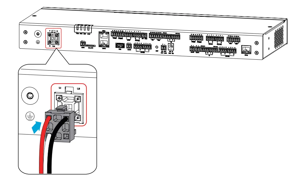
(Optional) Connecting the Three-Phase AC Cable
Warning
- When the inverter communicates with the EzLogger via PLC, connect the three-phase AC cable to the PLC port on the EzLogger.
- Ensure that the upstream switches are turned off before connecting the three-phase AC cables.
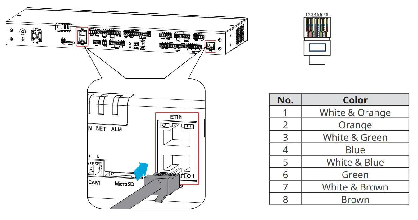
Connecting the Ethernet Cable
Notice
- ETH1 port is set to dynamic IP mode by default at the factory. It can be connected to a computer, router, switch, and other devices.
- ETH2 port is set to static IP mode by default at the factory, with the default IP address being 172.18.0.12. It can be connected to a computer for EzLogger configuration.
- The functionality of ETH3 port is reserved.
- Refer to Section 8.4.1 “Setting Port Parameters” for detailed instructions to modify the IP parameters of ETH1 and ETH2 ports.
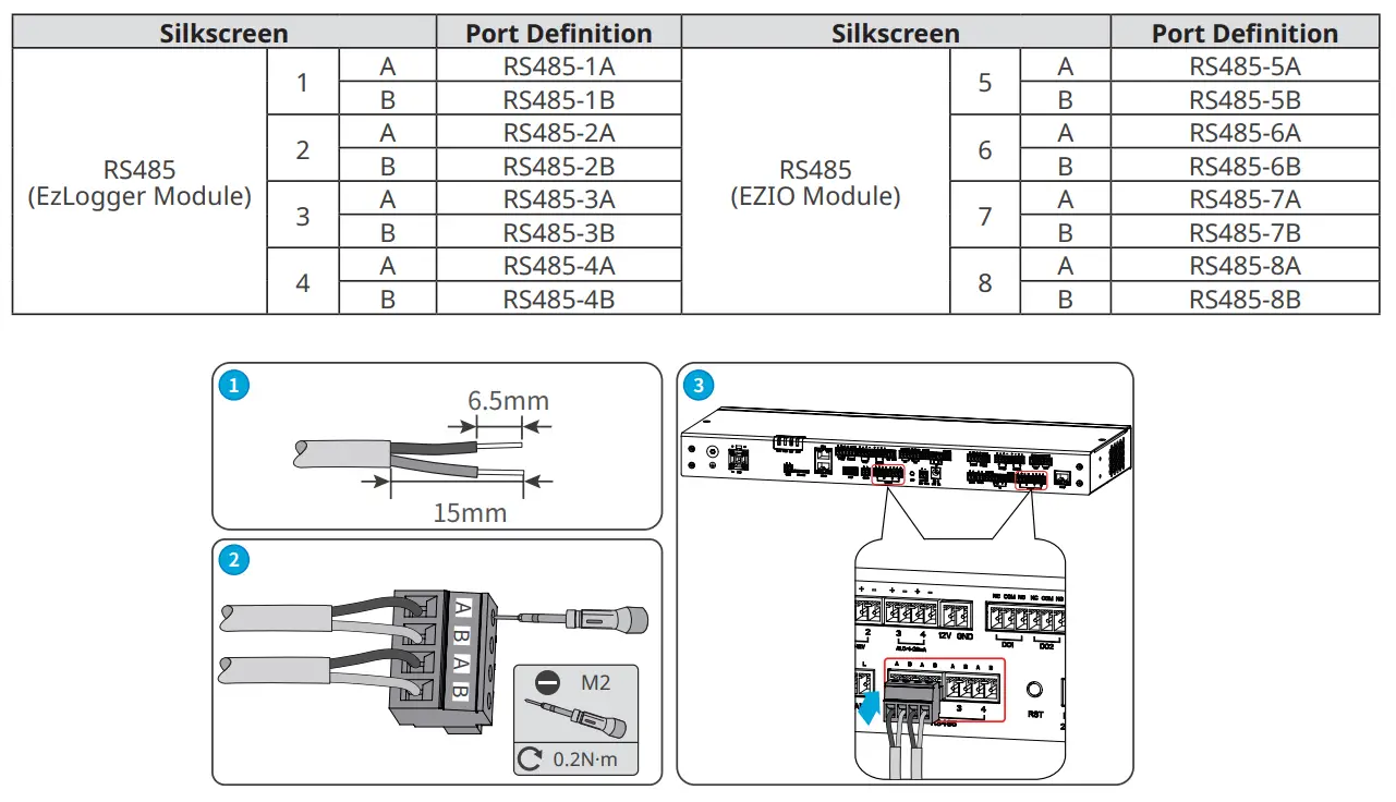
Connecting the RS485 Signal Cable
Notice
- The EzLogger can be connected to RS485 communication devices such as inverters, smart meters, and environmental monitoring instruments via its RS485 port.
- Make sure to connect the RS485A port and the RS485B port on the EzLogger with the RS485A signal and the RS485B signal , respectively of the other communication device.
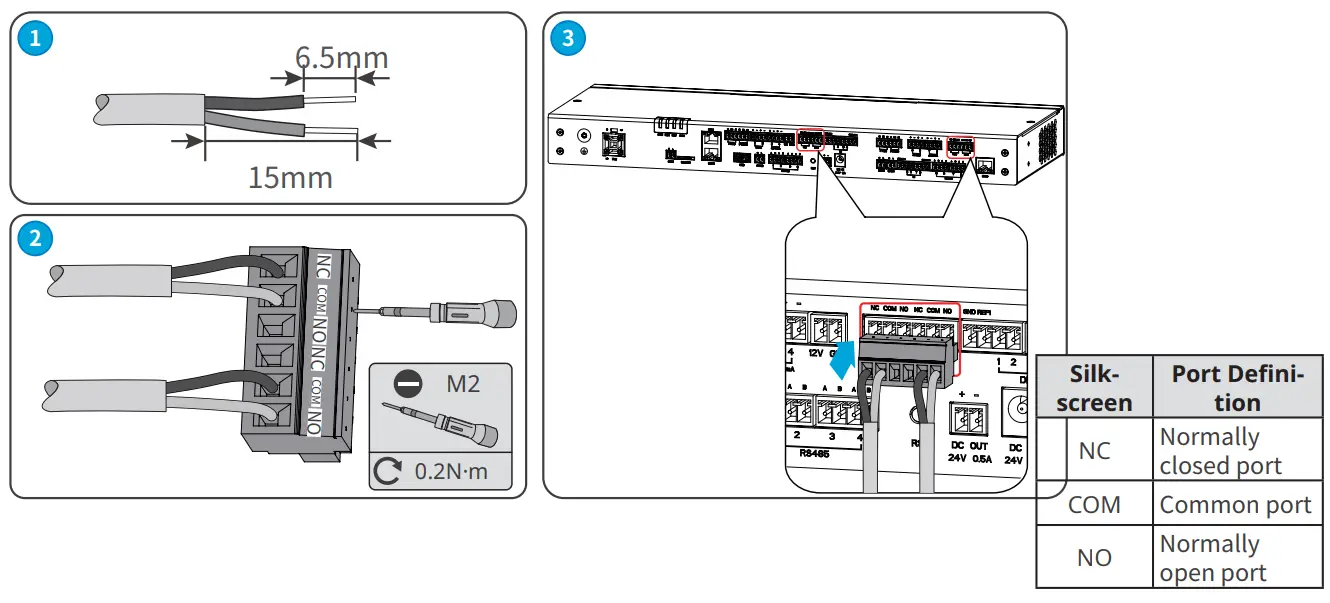
Connecting the DO Signal Cable
Notice
- The EzLogger DO port supports to connect with passive contact for signal output.
- The DO port of EzLogger supports a maximum signal voltage of 30V/1A. The NC/COM terminal is the normally closed terminal, and the NO/COM terminal is the normally open terminal.
- It is recommended to keep the signal transmission distance within 10 meters.
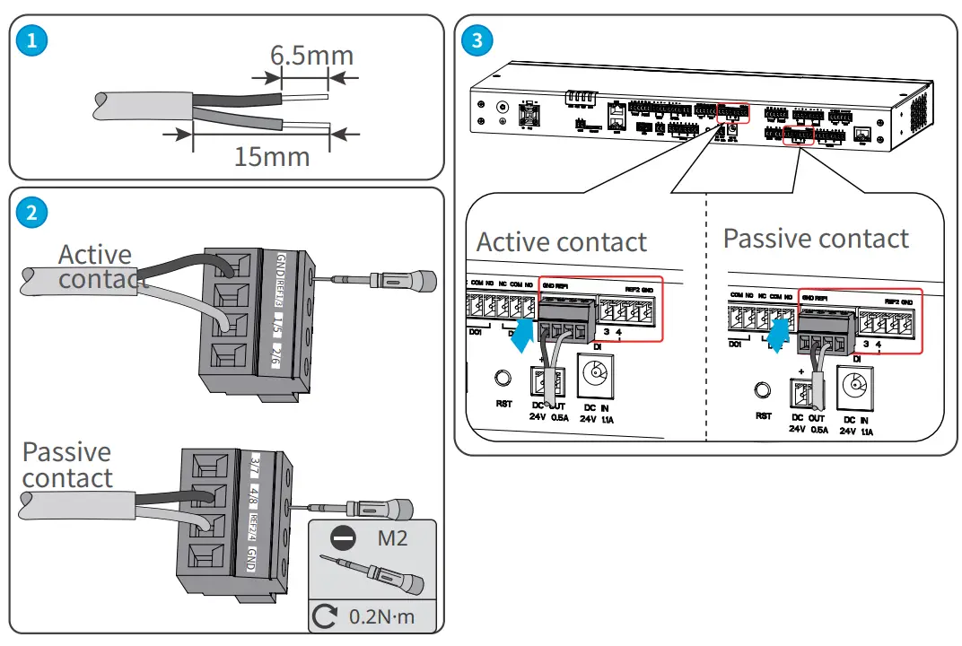
Connecting the DI Signal Cable
Notice
- The EzLogger supports connecting with passive contact and active contact for signal output.It is recommended to keep the DI signal cable transmission distance within 10 meters.
- It is recommended to keep the DI signal cable transmission distance within 10 meters.
Passive contact
| Function | Silkscreen | |
| DI1 | REF1 | 1 |
| DI2 | 2 | |
| DI3 |
REF2 |
3 |
| DI4 | 4 | |
| DI5 |
REF3 |
4 |
| DI6 | 5 | |
| DI7 |
REF4 |
1 |
| DI8 | 2 | |
Active contact
| Function | Silkscreen | |
| DI1 | GND | 1 |
| DI2 | 2 | |
| DI3 |
GND |
3 |
| DI4 | 4 | |
| DI5 |
GND |
4 |
| DI6 | 5 | |
| DI7 |
GND |
1 |
| DI8 | 2 | |
Connecting the PT Signal Cable
Notice
- The EzLogger can be connected with 2-wire or 3-wire PT100/PT1000 thermo sensors.
- When connecting a 2-wire PT100/PT1000 thermo sensor, it is necessary to short-circuit the B1 and B2 ports.
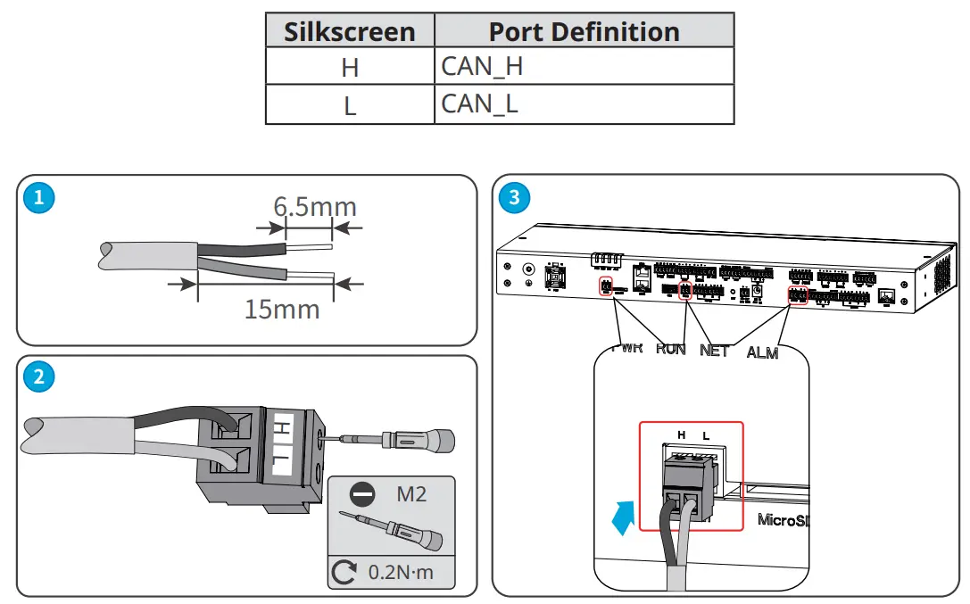
| Silkscreen | Port Definition | Silkscreen | Port Definition | ||
|
PT100 |
B1 | PT100_B1 |
PT1000 |
B1 | PT1000_B1 |
| B2 | PT100_B2 | B2 | PT1000_B2 | ||
| A1 | PT100_A | A2 | PT1000_A | ||
Installing the USB Port
Notice
- Install the USB flash drive into the USB port for software upgrading.
- Contact the after-sales service center to obtain the software upgrading package.
- Prepare a USB flash drive.
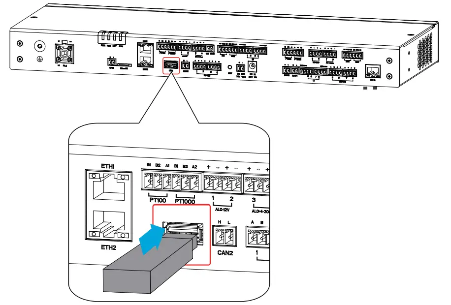
Connecting the CAN Signal Cable
Notice
Connect with the relevant devices supporting CAN signal communication.
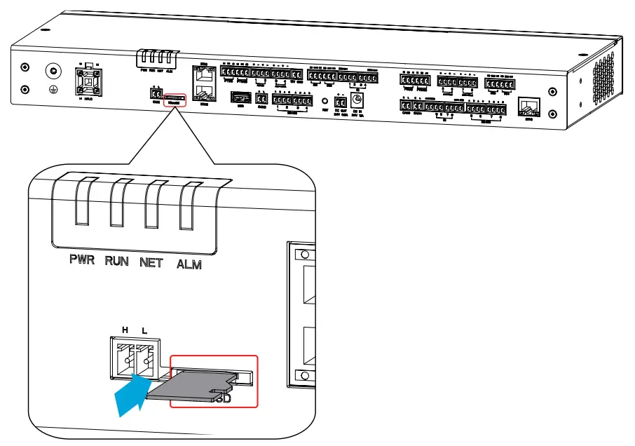
Inserting the MicroSD Card
Notice
- The MicroSD card can keep the running logs, operation logs, and maintenance logs of the EzLogger, which facilitates future maintenance.
- Use the storage card included with the package, with a capacity of 8GB.
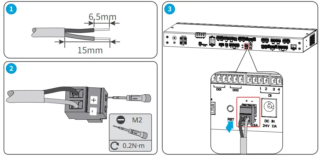
Connecting the 24V DC Output Cable
Notice
The EzLogger owns a 24V, 0.5A DC output port, which can provide power to other devices.
Connecting the 12V DC Output Cable
Notice
The EzLogger owns a 12V DC output port to provide power to other devices.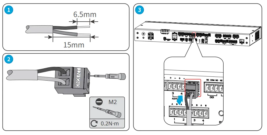
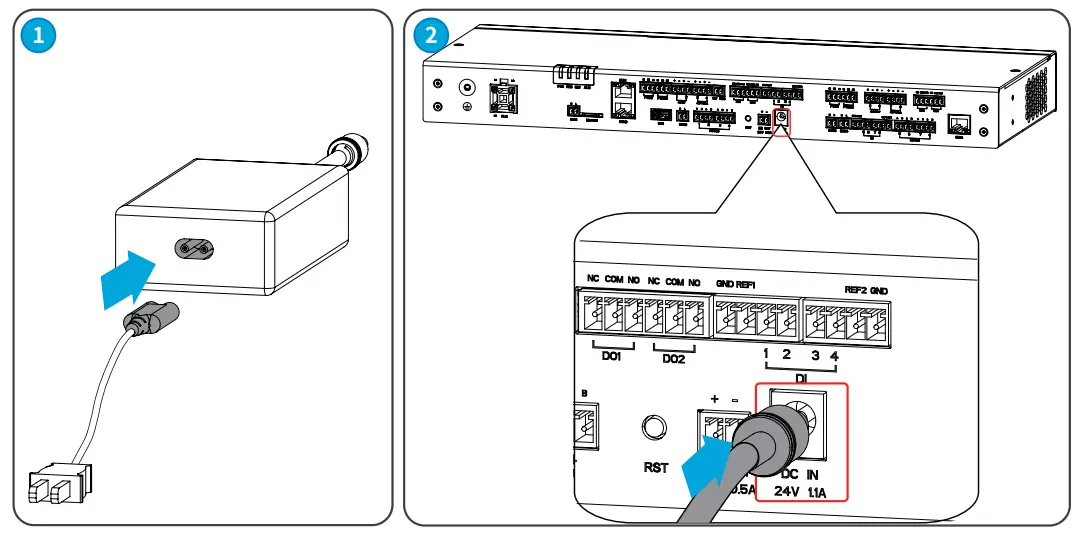
Connecting the DC Input Cable
Notice
- Connect the power adapter included in the package to the EzLogger’s DC input port for power supplying to the EzLogger.
- Power adapter specifications: Input: AC 100V~240V, 50Hz/60Hz; Output: DC 24V, 1.5A.
Equipment Commissioning
Check before Power On
| No. | Checking Item |
| 1 | The EzLogger should be securely installed in a location that is easily accessible for operation and maintenance, and the installation environment should be clean and tidy. |
| 2 | Ensure that the protective ground wire, DC input wire, DC output wire, and communication wire are
connected correctly and securely. |
| 3 | Cable ties are intact, routed properly and evenly. |
| 4 | The input signal and input power parameters of the EzLogger should be within the operating range of the
equipment. |
Power On
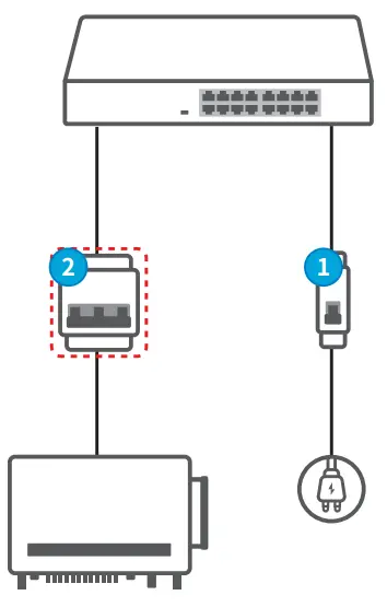
Step 1: Insert the power adapter into the AC socket and turn on the switch on the AC socket side. (Optional) Step 2: When using PLC signal communication, turn off the upstream switch of the three-phase AC input port.
System Commissioning
Indicators and Button
Indicators
| Indicator | Function | Descriptions |
| PWR | Power Status Indicator | Green off: the power supply of EzLogger is abnormal. |
| Green continues on: the power supply of EzLogger is normal. | ||
| RUN | Operating Indicator | Green flashes slowly: EzLoggerruns normally. |
|
NET |
NInedtiwcaotrokring Status | Green flashes twice: EzLogger is not connected to the router. |
| Gnoreteton tflhaesheextseqrnualrtnice:twEzoLrokgsgeerrveisr.properly connected to the router, but | ||
| Green continues on: The communication of EzLogger is normal. | ||
| ALM | Reserved | |
Buttons
| RST Button | Function |
| Press >5S | EzLogger restart and reset to |
| Press 1~3S | EzLogger restart. |
Maintenance
Routine Maintenance
Danger
When operating and maintaining the EzLogger, please ensure that the device is powered off. Operating the equipment while it is energized may result in equipment damage or electrical shock hazards.
| Maintaining Item | Maintaining Method | Maintaining Period |
| System cleaning | Check for any foreign objects or dust in the air intake/exhaust vents. | Once 6 months or
once a year |
| Electrical
Connection |
Check whether the cables are securely connected. Check whether the cables are broken or whether there is any exposed copper core. | Once 6 months or
once a year |
| Environmental
inspection |
Check for the presence of high electromagnetic interference devices or heat sources around the EzLogger. | Once 6 months or
once a year |
System Maintenance (WEB)
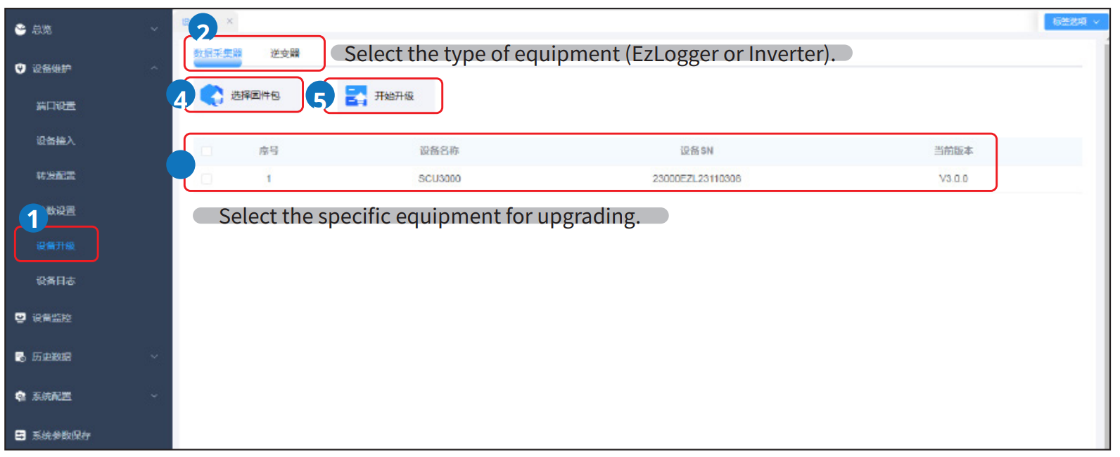
Updating
Notice
- Already obtained the upgrading package.
- Keep the upgrading package on the Local Disk of the computer. Or store the package into a USB flash drive, and insert the drive into the computer’s USB port.
Step 1: Upgrade the equipment as in following steps.
Maintaining the EzLogger System
Step 1 Maintain the EzLogger system as in following steps.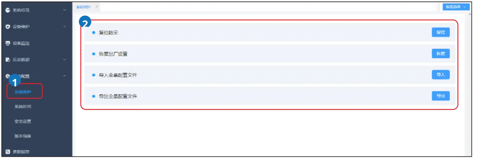
| Parameter | Description |
| System Reset | Perform a system reset, and the EzLogger will automatically shut down and
restart. |
|
Restore Factory Settings: |
After restoring factory settings, all parameter values that have been set (except for current date, time, and communication parameters) will be restored to the factory default state. Operational information, alarm records, and system logs will not be affected. Please proceed with caution when performing this operation. |
| Full Configuration File Export: | Before replacing the EzLogger, export the configuration file to the local storage. |
|
Full Configuration File Import: |
After replacing the EzLogger, import the previously exported configuration file from the local storage to the new EzLogger. Once the import is successful, the EzLogger will restart, and the configuration file will take effect. Confirm that the device parameters are correctly configured. |
Set System Time
Notice
Modifying the date and time will affect the integrity of the system’s power generation and performance data re-cords. Please refrain from changing the time zone and system time arbitrarily.
Step 1: Set the system time according to the following operation.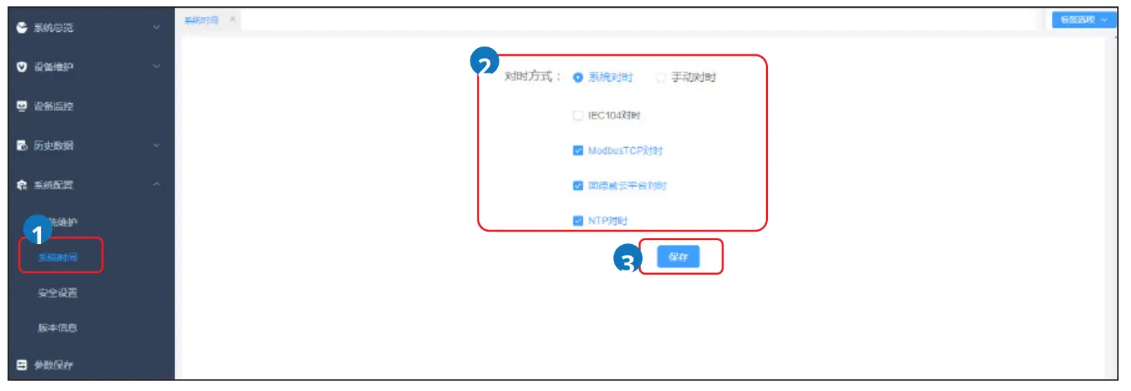
| Parameter Tab | Parameter | Description |
|
Time Synchronization Mode: |
System Time Synchronization: |
• Currently, time synchronization can be performed through IEC104, ModbusTCP, Goodwe Cloud Platform, or NTP server.
• For NTP time synchronization, set the IP address of the NTP server and the desired time interval for synchronization according to the actual requirements. |
| Manual Time
Synchronization: |
Set the local time zone, date, and time based on actual settings. |
Power Off
Danger
- Power off the equipment before operations and maintenance. Otherwise, the equipment may be damaged or electric shocks may occur.
- Delayed discharge. Wait for a minimum of 60 seconds until the components are discharged after power off.
(Optional) Step 1 When using PLC signal communication, turn off the upstream switch of the PLC cable connected the EzLogger.
Step 2 Unplug the power adapter from the socket.
Removing the EzLogger
Warning
- Ensure the equipment is powered off.
- Wear PPEs during operation.
Step 1 Disconnect all electrical connections of the equipment, including DC cables, communication cables, and protective ground wires.
Step 2 Remove the equipment.
Step 3 Store the equipment properly. If the equipment will be used again in the future, ensure that the storage conditions meet the requirements.
Disposing of the EzLogger
If the equipment cannot work any more, dispose of it according to the local disposal requirements for electrical equipment waste. Do not dispose of it as household waste.
Troubleshooting
Perform troubleshooting according to the following methods. Contact the after-sales service if these methods do not work. Collect the information below before contacting the after-sales service, so that the problems can be solved quickly.
- Equipment information like serial number, software version, installation date, fault time, fault frequency, etc.
- Installation environment. It is recommended to provide some photos and videos to assist in analyzing the problem.
- Utility grid situation.
| No. | Fault | Cause | Solutions |
|
1 |
The equipment is not able to power on. |
The power input port of the equip- ment is not securely connected. | Reconnect the power input ports. |
| The power adapter is not securely connected to the socket. | Reconnect the power adapter to the socket. | ||
| The power adapter is malfunction- ing. | Replace the power adapter. | ||
| Equipment malfunction | Contact your distributor or after-sales service
center. |
||
|
2 |
ETH communication abnormal |
Ethernet cable is not properly con- nected. | Reconnect the Ethernet cable. |
| Failed IP address communication between the EzLooger and other equipments connected via Ethernet cable |
Double-check and set the equipment’s IP address to establish successful communication. |
||
| Switch or router abnormal | Replace the switch or router. | ||
| Equipment malfunction | Contact your distributor or after-sales service
center. |
||
|
3 |
RS485 communication abnormal |
RS485 wiring abnormal | Check if the cable connections are correct and secure. |
| RS485 communication parameter
setting abnormal |
Recheck and set the RS485 communication param- eters. | ||
| Equipment malfunction | Contact your distributor or after-sales service
center. |
||
|
4 |
PLC communication abnormal |
PLC wiring abnormal | Ensure that the PLC cables are properly connected
and the switches are closed correctly. |
| PLC communication parameter setting abnormal | Check if the PLC communication mode is set correctly, including the equipment ID. | ||
| Equipment malfunction | Contact your distributor or after-sales service
center. |
Technical Parameters
| Technical Parameters | EzLogger3000C | |
|
Power Supply |
Voltage input range | 100Vac-240Vac |
| Frequency | 50Hz/60Hz | |
| Output voltage | 24V DC | |
| Rated output current | 1.5A | |
| Power consumption | £15W | |
|
Environment |
||
| Operating temperature | -30℃~+60℃ | |
| Storage Temperature | -30℃~+70℃ | |
| Relative humitity (non-con- densing) | £ 95% | |
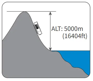
| Max. Operating Altitude | ≤ 5000m | |
| IP rating | IP20 | |
|
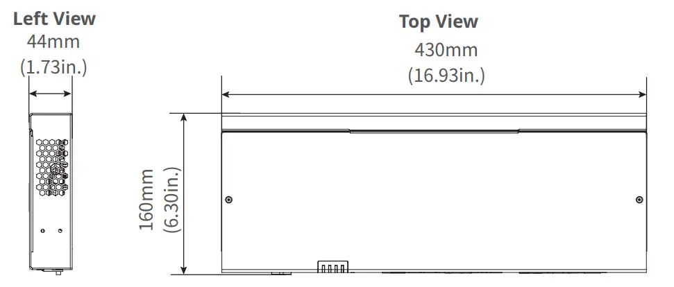
Mechanical |
Dimensions (L * W * H) | 256×169×46mm |
| Installation method | Wall mounting, table surface mounting, rail mounting | |
| Communication Interface | RS485 | 4 |
| LAN | 2 | |
| Digital Input (DI) | 4 | |
| Digital Output (DO) | 2 | |
| Analog Input (AI) | 2 (4~20mA)
2 (0~12V) |
|
| PT100/PT1000 | 2 | |
| USB | 1 | |
| CAN | 2 | |
| SD | 1 | |
| WIFI | 1 | |
| BLE | 1 | |
| Display | Indicator light | 4 |

Contact
GoodWe Technologies Co.,Ltd.
- No. 90 Zijin Rd., New District, Suzhou, 215011, China
- www.goodwe.com
- service@goodwe.com
FAQ
- Q: Can I mount the EzLogger3000C on a wall?
- A: Yes, the EzLogger3000C can be wall-mounted. Refer to section 5.2.1 for detailed instructions.
- Q: How do I update the system time on EzLogger3000C?
- A: System time can be updated through the web interface. Follow the steps outlined in section 9.2.3 of the user manual.
Documents / Resources
 |
GOODWE EZLOGGER3C Smart Data Logger [pdf] User Manual EZLOGGER3C, 2AU7J-EZLOGGER3C, 2AU7JEZLOGGER3C, EZLOGGER3C Smart Data Logger, EZLOGGER3C, Smart Data Logger, Data Logger, Logger |