![]() Eyevision Two Wire
Eyevision Two Wire
Video Intercom Systems
Accessories
IP Gateway Converter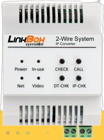
![]() EV-LinkBox-V01.02
EV-LinkBox-V01.02
User Manual
Eyevision LinkBox
IP Gateway Converter
Please read this manual carefully before using the product you purchase, and keep it well for future use.We reserve the right to modify the specification in this manual at any time without notice.
IP Gateway Converter Operating Instructions
Application:
Eyevision® 2 wire LinkBox module can be used to divert calls to phone with internet connection
With Internet:
Divert calls to mobile from Eyevision® LinkBox.
- Diverts immediately on the monitor, If the “DO NOT DISTURB” mode is ON
- If “DO NOT DISTURB” mode is OFF that will divert calls after 30 sec. Without Internet: As Memory Module provide 200 photos memory for all monitor connected.
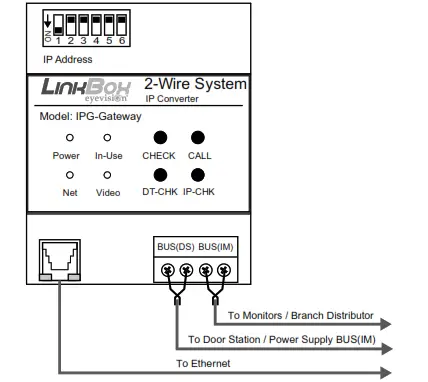
Terminal Description:
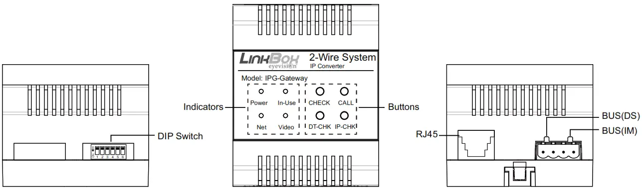
Connection Ports
RJ45: Network connection terminal.
BUS(IM): Indoor monitor connection terminal.
BUS(DS): Door station connection terminal.
We reserve the right to modify the speciecation in this manual at any time without notice.
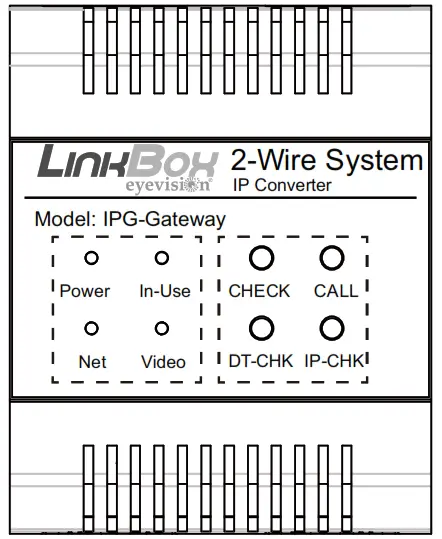
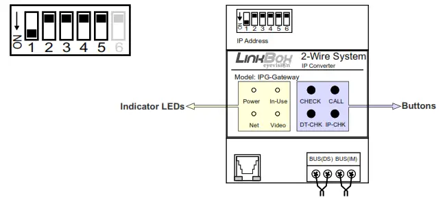
Indicators:
On Eyevision LinkBox, there are DIP Switches, Buttons and Indicator LEDs for setup Eyevision LinkBox, bellows are some generally explains.
DIP Switch:
When DIP Switches all in OFF position, means Eyevision LinkBox is in Dynamic IP ad dress.
Subnet address please refer to the followings in detail.
Buttons:
The buttons operate as shown below
| Status | |||
| Buttons | Press once | Press until “In-use” on | Press until “Video” on |
| CHECK | Copy picture and log to SD card. |
Delete all call logs and format SD card, twice to confirm. |
|
| CALL | |||
| DT-CHK | DT 2 -Wire door stations and monitor online check. |
*Long press 4 times to initialize Eyevision LinkBox, format all data. |
|
Indicator LEDs:
Indicators LEDs mean as described below.
| Status | ||||
| LEDs | off | Solid On | Quick flash | Regularly flash |
| Power | No Power | Standby and power on | Starting | |
| In-use | Standby/No Power | In auto-testing | ||
| Net | Not connected | Connected without SIP registered | Connected with SIP registered |
|
| Video | Standby/No Power | As video output | Recording/Play back | |
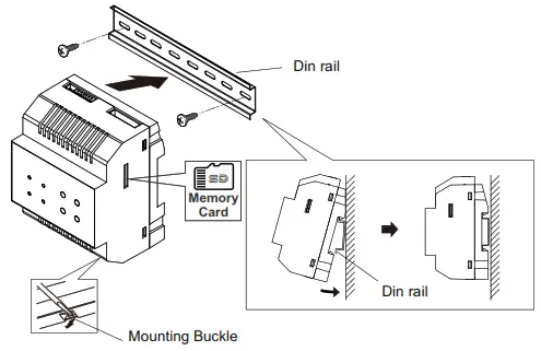
Mounting:
Step1: Mount the din rail to the wall with screws;
Step2: Pull down the mounting buckle, and hang the LinkBox on din rail.
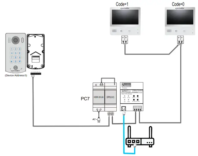
Wiring:
Basic Connection

Multi Monitors Connection
Specification:
| Power: | 2-wire bus (26V, no-polarity) |
| Consumption current: | Standby 109mA, maximum131mA |
| LAN Ethernet: | 10BASE-T, 100BASE-TX |
| Audio codec: | G.711(64Kbps) |
| Video codec : | H.264/AVC (VGA, QVGA) |
| Network Protocol: | IPv4, TCP, UDP, RTSP, RTP, RTCP, IGMP, DHCP, NTP |
| Operating temperature: | 0 °C ~ +40 °C |
| Dimension: | 72*90*60mm |
Note
____________________________________________
![]()
Eyevision Two Wire
Video Intercom Systems
The design and specifications can be modified without notice to the user. Right to interpret and copyright of this manual are reserved.
Documents / Resources
 |
eyevision IP Gateway Converter Two Wire Video Intercom System [pdf] User Manual Two Wire Video Intercom System, Two Wire Video Intercom, Video Intercom System, Video Intercom, Two Wire Video System, Two Wire System IP Converter |


