![]() Access Controller/Reader
Access Controller/Reader
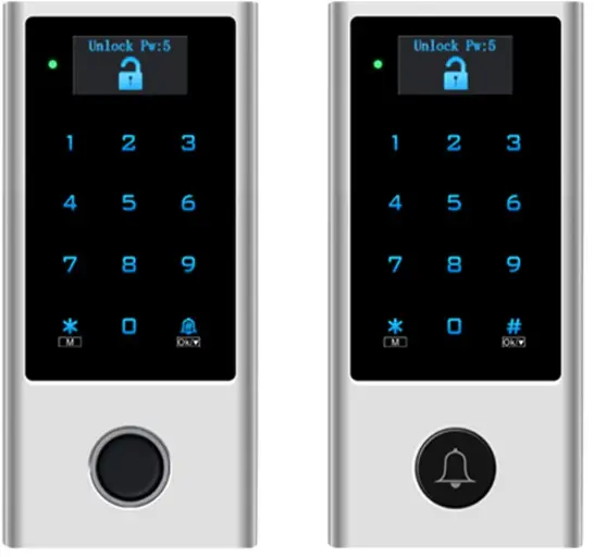
Card /PIN
Card/ PIN/ Fingerprint
User Manual
INTRODUCTION
The device is a single door multfunciion standaione access controller or Wiegand output reader with OLED display.t uses Atmel MCU assuring stable performance. The operationis very user-rendy, and low-power circuit makes it long service .
The devics can be made with Biuetooth function or with WIFI function.
Cardl PIN device:
It supports 10,000 users (9988 common + 2 panic + 10 visitor)
Cardl PIN/ Fingerprint device:
Threo usor capacilies are available
- 10,000 card/ PIN users + 500 fingerprint users (standard version)
- 10,000 carl PIN users + 100 fingerprit users.
- 10,000 card/ PIN users + 880 fingerprint users
Features
- OLED display, touch keypad
- Metal case, anti-vandal
- Waterproof, conforms to IP66
- One relay
- PIN length: 4~6 digits
- EM card, EM+ Mifare card optional
- EM card: Wiegand 26~44 bits input & output
- Mifare card: Wiegand 26~44bits, 56bits, 58bits input & output
- Can be used as Wiegand reader with LED & buzzer output
- Card block enrollment
- Tri-color LED status display
- Integrated alarm & buzzer output
- Pulse mode, Toggle mode
- User data can be transferred
- 2 devices can be interlocked for 2 doors
- Built-in light dependent resistor (LDR) for anti tamper
- Backlit keypad, can set automatic OFF after 20 seconds
Specifications
| User Capacity | Card/ PIN | Card/ PIN/ Fingerprint |
| Common Card/ PIN User Common Fingerprint User Panic User Visitor User |
9988 / 2 10 |
9988 500 (100,880 optional) 2 10 |
| Operating Voltage Working Current Idle Current |
12˜28V AC/DC ≤150mA ≤60mA |
|
| Proximity Card Reader
Radio Technology Read Range |
EM or EM+Mifare
125KHz or 125KHz+ 13.56MHz 2-6 cm |
|
| PIN Length | 4-6 digits | |
| Wiring Connections | Relay Output, Exit Button, Alarm, Door Contact, Wiegand Input, Wiegand Output |
|
| Relay Adjustable Relay Output Time Lock Output Load |
One (NO, NC, Common) 0-99 Seconds (5 seconds default) 2 Amp Maximum |
|
| Wiegand Interface PIN Output |
EM card version: Wiegand 26-44 bits input & output (Factory Default: Wiegand 26bits) Mifare card version: Wiegand 26-44bits, 56bits, 58bits input & output (Factory Default: Wiegand 34bits) 4 bits, 8 bfts(ASCII), 10 digits Virtual Number (Factory Default:4 bits) |
|
| Environment Operating Temperature Operating Humidity |
Meets IP66 -40°C ˜ 60°C (-40°F˜ 140°F) 0 %RH-98%RH |
|
| Physical Colour Dimensions Unit Weight Shipping Weight |
Zinc-Alloy Silver & Black L145 x W68 x D25 (mm) 500g 615g |
|
Wiring
| Wire Color | Function | Notes |
| Basic Standalone Wiring | ||
| Red | AC&DC | 12-28V AC/DC Regulated Power Input |
| Black | AC&DC | 12-28V AC/DC Regulated Power Input |
| Grey&Black | GND | Negative Pole |
| Blue & Black | Relay NO | Normally Open Relay Output (install diode provided) |
| White & Black | Relay Common | Common Connection for Relay Output |
| Green & Black | Relay NC | Normally Closed Relay Output (Install diode provided) |
| Yellow | OPEN | Request to Exit(REX) Input |
| Pass-Through Wiring (Wiegand Reader or Controller) | ||
| Green | Data 0 | Wiegand Output (Pass-through) Data 0 |
| White | Data 1 | Wiegand Output (Pass-through) Data 1 |
| Advanced Input and Output Features | ||
| Grey | Alarm Output | Negative contact for Alarm |
| Brown | Contact Input | Door/Gate Contact Input (Normally Closed) |
| Brown & Black | Doorbell A | Contact for Doorbell |
| Yellow & Black | Doorbell B | Contact for Doorbell |
Carton Inventory

INSTALLATION
- Remove the back cover from the urit
- Drill 2 holes(A,C) on the wall for the screws and ane hole for the cable
- Knock the supplied rubber bungs o the screw holes(A,C)
- Fixthe back cover firiy on the wall with 4 fat head screws.
- Thread the cable through the cable hole(B)
- Altach the unitto the back cover

CONNECTION DIAGRAM
Standalone Mode
The devioe can work as Standalone Access Controlforsingle door.
(Factory default mode)
Connection Diagram
Common Power Supply

Attention:
Install a 1N4004 or equivalent diode is needed when use a common power supply, or the keypad might be damaged. (1N4004 is included in the packing)
Access Control Power Supply

Controller Mode
The device can work as Controller, connected with the external Wiegand reader.
(Factory default mode)
Connection Diagram

Attention: Install a 1N4004 or equivalent diode is needed when use a common power supply, or the reader might be damaged. (1N4004 is included in the packing)
WIEGAND READER MODE
The device can work as Standard Wiegand Reader, connected to the third party Controller
Connection Diagram

Notes:
- When set into Wiegand Reader mode, nearly all settings in Controller Mode will become invalid, and Brown & Yellow wires will be redefined as below:
– Brown wire: Green LED light control
– Yellow wire: Buzzer control - If you need to connect Brown/Yellow wires:
When the input voltage for LED is low, the LED will tum into Green; and when the input voltage for Buzzer is low, it will sound.
PROGRAMMING
Keys & Functions
![]() 0~9: Enter value, menu number
0~9: Enter value, menu number
# Ok means confirm
▼means down to select
![]() Means doorbell
Means doorbell
![]() M means menu
M means menu
Short press * means back to the previous menu
Long press * means back to main interface
System Menu
- Please input * (Master Code) # to enter system menu. (Factory default master code is 123456)
- User ID number: The Common Card/PIN User ID: 1-9988
Panic User ID: 9989-9990 Visitor User ID: 9991-10000
Fingerprint User ID (Only apply to card/PIN/ Fingerprint device) 10001-10100 or 10001-10500 or 10001-10880
- PIN: Can be any 4-6 digits
- Proximity Card: 125KHz EM card or 13.56MHz Mifare card
- Change Admin Press ‘1’ to enter Change Admin.
Menu No. Setting Note 1 Change Admin New Admin can be any 6 digits - User Setting
Press ‘2’ to enter User Setting.
Press ▼ to select and long press # to confirm.Menu No. Setting Note 1 Add Directly Add users directly by inputting PIN/ card 2 Add by ID Add users by user ID.
The common user ID is between 1-9988, panic User ID is 9989-9990.
Fingerprint User ID (Only apply to card/PIN/ Fingerprint device) is 10001-10100 or 10001-10500 or 10001-10880.3 Add Visitor – Visitor user ID is between 9991-10000 -Add visitor card: ID# (1-9)# (read card) -Add visitor PIN: ID# (1-9)# (PIN)# 1-9 means times of usage. 4 Block Enrol Choose the 1st ID–Set Card Number (can set 1-200)– Read the 1st number card 5 Del Directly – Enter PIN or card to delete user directly 6 Del by ID – Delete users by inputting user ID 7 Del All User – Delete ALL users - Door Setting
Press ‘3’ to enter Door Setting.
Press ▼ to select and long press # to confirm.Menu No. Setting Note 1 Open Time – Open time can be set to 0-100s Input 0-100, long press # to confirm. – Factory default is 5s 2 Access Mode Access Modes can be set to:
Card/ PIN device: 1 Card, 2 PW, 3 Card/PW, 4 Multi User (max.9)
Card/ PIN/ Fingerprint device: 1 Card, 2 PW, 3 Fingerprint, 4 Card/PVV/Fp, 5 Multi User (max.9)3 Alarm Time -1 OFF (Factory default)
– 2 lmin
– 3 2min
– 4 3min4 Door Contact -1 OFF (Factory default) – 2 ON 5 Security Mode – 1 OFF (Factory default)
– 2 LOCK DeadThe device will become ‘access deny’ for 10 minutes after 10 failed entry attempts. Restart the device to back to normal.– 3 Alarm Mode
The device will alarm after 10 failed entry attempts. Alarm time depends on the device alarm time (refer to Door Setting Menu No. 3 Alarm Time),enter Master Code # or valid user card/PIN to silence.6 Interlock -1 OFF (Factory default)
– 2 ON
Connection Diagram please refer to page 127 Collect Card -1 OFF (Factory default)
– 2 ON
After this function is turned ON, all cards can open the lock, at the same time, the card is added to the device.8 WG FMT – 1 Check OFF
– 2 Check ON (Factory default)
Check means Parity Bit
– 3 4bits (Factory default)
– 4 8bits
– 5 10bits (VirNum)
-6 ID: 26
Wiegand format for EM card can be set to 26-44.
– 7 IC: 34
Wiegand format for Mifare card can be set to 26-58.9 Working Mode – 1 Controller (Factory default)
– 2 Reader
In Controller mode, the device can be also used as standalone.
Connection diagram please refer to Page 4-6 - Other Setting
Press ‘4’ to enter Other Setting.
Press ▼ to select and long press # to confirm.Menu No. Setting Note 1 Sound -1 OFF
– 2 ON (Factory default)2 Red Led -1 OFF
– 2 ON (Factory default)3 Keys Backlight -1 OFF
– 2 ON
– 3 Auto (Factory default)
Automatic OFF after 20 seconds, it will go ON by pressing any key (this key isn’t taken Into considerations).4 OLED Backlight – 1 ON
– 2 5S
– 3 10S
– 4 30S (Factory default)
– 5 1min5 Unbind Machine – Unbind the device with Bluetooth.
– Long press # to confirm Unbind, the device will back to main interface after unbinding successfully.6 Copy Users Connection diagram please refer to page 11 7 Factory Reset Reset to factory default, the user’s information is still retained.
ADVANCED APPLICATION
User Information Transfer (Valid for Card/ PIN device)
The device supports the User Information Transfer function, and the enrolled user (cards, PINs) can be transferred from one (let’s name it Master Unit) to another (let’s name it Accept Unit).
Connection Diagram:

Remarks:
- The Master units and Accept units must be same series devices.
- The Master Code of the Master Unit and the Accept Unit must be set to the same.
- Program the transfer operation on Master Unit only.
- If the Accept Unit is already with the users enrolled, it will be covered after transferring.
- For full 10000 users enrolled, the transfer takes about 5 minutes.
Set Transferring on Master Unit: Menu 4 Other Setting—- 6 Copy User
Interlock
The device supports the Interlock Function. It is of two Devices for two doors, and mainly used for banks, prisons, and other places where a higher level security is required.
Connection Diagram:

Remarks: The Door Contact must be installed and connected as the diagram.
Let’s name the two Devices as “A “and “B” for two doors “1” and “2”
Step 1:
Enroll the users on Device A, then transfer the users’ information to Device B by ‘User Information Transfer’ function (Page 111)
Step 2:
Set both of the two Devices (A and B) to Interlock function Menu 3 Door Setting — 6 Interlock
If enable interlock, when and only door 2 is closed, the user can read the valid fingerprint/card or input PIN on Reader A, door 1 will open; then when and only door 1 closed,read valid fingerprint/card or input PIN on Reader B, door 2 will open.
SOUND AND LIGHT INDICATION
| Operation Status | LED | Buzzer |
| Stand by | Red light bright | – |
| Enter into programming mode | Red light shines | One beep |
| In the programming mode | Orange light bright | One beep |
| Operation error | – | Three beeps |
| Exit from the Programming mode | Red light bright | One beep |
| Open lock | Green light bright | One beep |
| Alarm | Red light Shines quickly | Beeps |
![]()
Documents / Resources
 |
EXPERT4HOUSE HD1 Access Controller Reader [pdf] User Manual HD1, HD1 Access Controller Reader, Access Controller Reader, Controller Reader, Reader |