AUTEC XMP-TMC2457-UP Access Control Card Reader User Manual
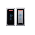
The badge readers type XMP-TMC24x7-UP are designed for use in access control applications in combination with the management software XMP-BABYLON. The readers read passive contactless badges with standard RFID technology in the frequency range 13.558 MHz (MIFARE Classic® & MIFARE® DESFire® EV1 / EV2 / EV3).
The card readers are connected to the door controllers XMP-K32 / XMP-K32SX / XMPK32EX / XMP-K6EX / XMP K12 / XMP-K12EX / XMP-CMM / XMP-CMM-EX or as second card reader to the IP terminal XMP-TMC3500/3600 via an RS485 interface. The data transmission between reader and controller is encrypted with an AES-256 GCM (SecuCrypt®2.0) or via AES-128 (OSDP™ V2 Crypto).
Technical data
| Beschreibung | XMP-TMC2457-UP | ||
| Processor | ARM 180 MHz | ||
| Program memory | 1 MB Flash 136 KB RAM | ||
| Power supply | 12 bis 24 V DC ±10% | ||
| Power consumption | 78 bis 397 mA bei 12V DC 36 bis 176 mA bei 24V DC | ||
| Interfaces | RS485 (2 Wire) | ||
| Baud rate | 9600 oder 19200 | ||
| Tamper Switch | x | x | x |
| Beeper | x | x | x |
| 3 LED status indicator | x | x | x |
| Dip-Switch | x | x | x |
| Housing Jung LS994 & GIRA | x | x | x |
| Protection class IP54 | x | x | x |
| Environmental conditions | Operation: -20 bis 75°C (-4 to 167°F) Storage: -20 bis 75°C (-4 to 167°F)5 bis 90% Relative humidity | ||
| Dimensions | see chapter “Order numbers“ | ||
Maintenance – Cleaning– Disposal
Defective circuit boards must be disposed of properly. Batteries and rechargeable batteries belong in hazardous waste. The packaging can be reused or disposed of.
Dispose of green filling material in the organic waste.
The reader should only be cleaned dry, with the aid of a dust rag, brush or vacuum cleaner. If the housing is heavily soiled, a mild, non-aggressive cleaning agent can be used.
Protection Class
| Protection class | IP54 |
![]()
- IP54 when mounted
- The maximum achievable degree of protection is IP54.
- Cable entries and mounting holes must be sealed with a sealant if necessary.
- Suitable sealants (e.g. silicone) must be selected according to the ambient conditions.
Order Number
| Order-Nr. | Description | Dimensions |
 XMP-TMC2457-UP |
Flush-mounted card reader MIFARE® classic/DESFire® EV1 / EV2 / EV3 for connection to door controller | 71 x 71 x 24 mm |
| XMP-TMC2457-UP-CH | Flush-mounted card reader MIFARE® classic/DESFire® EV1 / EV2 / EV3 for connection to door controller(Switzerland variant) | 71 x 71 x 24 mm |
| XMP-TMC2457-UP-BLE | Flush-mounted card reader MIFARE® classic/DESFire® EV1 / EV2 / EV3 card reader including Bluetooth module forconnection to door controller | 71 x 71 x 24 mm |
Blind cover Jung LS994
|
|
Jung LS994 blind cover for XMP-TMC24xx-UP card reader ( alpine white ) | 70 x 70 x 11 mm |
| XMP- TMC24-UP-002 | Jung LS994 blind cover for XMP-TMC24xx-UP card reader ( white ) | 70 x 70 x 11 mm |
| XMP- TMC24-UP-003 | Jung LS994 blind cover for XMP-TMC24xx-UP card reader ( light gray ) | 70 x 70 x 11 mm |
| XMP- TMC24-UP-004 | Jung LS994 blind cover for XMP-TMC24xx-UP card reader ( aluminum ) | 70 x 70 x 11 mm |
| XMP- TMC24-UP-005 | Jung LS994 blind cover for XMP-TMC24xx-UP card reader ( stainless steel ) | 70 x 70 x 11 mm |
| XMP- TMC24-UP-006 | Jung LS994 blind cover for XMP-TMC24xx-UP card reader ( black ) | 70 x 70 x 11 mm |

Blind cover Gira
|
|
Gira blind cover for XMP-TMC24xx-UP card reader ( white ) | 55 x 55 x 11 mm |
| XMP- TMC24-UP-012 | Gira blind cover for XMP-TMC24xx-UP card reader ( aluminum ) | 55 x 55 x 11 mm |
| XMP- TMC24-UP-013 | Gira blind cover for XMP-TMC24xx-UP card reader ( anthracite ) | 55 x 55 x 11 mm |
Software license
| Description | Order-Nr. |
| CIPURSE™ (SAM) Support | XMP-TMC2457-F1 |
| SAM Support for SecuCrypt® Customkey and MIFARE Classic® & MIFARE® DESFire® EV1/EV2/EV3 Keys | XMP- TMC2457-F2 |
| Bluetooth Support – XMP2GO® | XMP- TMC2457-F4-1 |
| Bluetooth Support – KleverKey Classic | XMP- TMC2457-F4-2 |
| Bluetooth Support – BlueID | XMP- TMC2457-F4-3 |
System connection
Up to 2048 controllers with 2, 4 or 8 card readers each can be connected to one server.

![]()
Defective printed circuit boards must be disposed of properly. Batteries and accumulators belong in the hazardous waste. The packaging can be reused or disposed of. Dispose of the green filling material in the organic waste.
Connection Reader to Door controller
![]()
- The supply voltage can be supplied centrally from the XMP-K12 / XMP-K32 (recommendation).
The following ranges must be observed: - Maximum distance between controller and reader up to 100m at 12VDC and 200m at 24VDC.
- Cable type: 2x2x0,8mm (with shielding braid)
Further information can be found in the respective manuals of the door controllers.
The readers can be connected in a star or bus configuration. (Observe fuse values!).

Meaning of Dipswitch SW1
Dipswitch SWI |
Description |
| SW1-1 | Bit 1, 2 and 3 fur Hardwarea dress (Adr. 0 bis 7) |
| SW1-2 | |
| SW1-3 | |
| SW 1-4 | Reserved |
| SW1-5 | Baud rate 9.200 (OFF) oder 19.200 (ON) |
| SW1-6 | OSDP |
| SW 1-7 | Reserved |
| SW1-8 | Boot loader-Mode actives (only for Service) |
The reader address is set at microswitches 1-3 in binary form as follows:

| Dip 1 | Dip2 | Dip 3 | Address |
| Off | Off | Off | 0 |
| On | Off | Off | 1 |
| Off | On | Off | 2 |
| On | On | Off | 3 |
| Off | Off | On | 4 |
| On | Off | On | 5 |
| Off | On | On | 6 |
| On | On | On | 7 |
Meaning of LEDs
The readers have 3 LEDs for status display.
| LED Status | Meaning |
| Yellow on | Operational readiness |
| Yellow flashing at 0.5 second intervals | No communication to the door control unit |
| Red on | Not authorized |
| Green on | Authorized |
| Yellow and red flashing at 0.5 second intervals | Boot loader program activated |
| Yellow, red and green on | Reader locked |
| Back side D11 | Communication TXD |
| Back D12 | Communication RXD |
Notes on the reading procedure
13,56 MHz – MIFARE® classic® & DESFire® EV1 / EV2 / EV3
The XMP-TMC2457-UP reads the serial number or memory information of MIFARE® DESFire® EV1 / EV2 / EV3 and classic® badges. For MIFARE® classic® badges the serial number of the badge (UID) is transmitted decimal (e.g. 40004403886360 for 4-byte UID) or hexadecimal (e.g. 800A345CB1986A for 7-byte UID) and for MIFARE® DESFire® EV1 / EV2 / EV3 badges as 7-byte HEX information (e.g. 801B76A1726F04) in 14 digits. After delivery, the reader reads the serial number of the corresponding badge. The reader receives the special parameterization for reading the memory information via the W3XMPCRP utility program.
The SecuCrypt® protocol is assumed as the communication protocol. The selection for setting for the desired reading procedure is realized via a selection menu.
![]() Recommended card type: ISO cards
Recommended card type: ISO cards
Reading distances
| MIFARE® classic® | MIFARE® DESFire® EV1 / EV2 / EV3 | |
| UID | Up to6 cm | Up to 6 cm |
| Memory / segment | Up to3 cm | Up to 3 cm |
![]() Metal parts at a distance of 120 mm from the reader can reduce this distance.
Metal parts at a distance of 120 mm from the reader can reduce this distance.
![]() A distance of at least 20 cm should be maintained between two installed card readers. Otherwise, the electromagnetic fields may influence each other.
A distance of at least 20 cm should be maintained between two installed card readers. Otherwise, the electromagnetic fields may influence each other.
Compliances
FCC INFORMATION (U.S.A.)
This equipment has been tested and found to comply with the limits for a Class B digital device, pursuant to part 15 of the FCC Rules. These limits are designed to provide reasonable protection against harmful interference in a residential installation.
This equipment generates, uses, and can radiate radio frequency energy and, if not installed and used in accordance with the instructions, may cause harmful interference to radio communications. However, there is no guarantee that interference will not occur in a particular installation. If this equipment does cause harmful interference to radio or television reception, which can be determined by turning the equipment off and on, the user is encouraged to try to correct the interference by one or more of the following measures:
- Reorient or relocate the receiving antenna.
- Increase the separation between the equipment and receiver.
- Connect the equipment into an outlet on a circuit different from that of which the receiver is connected.
- Consult the dealer or an experienced radio/TV technician for help.
FCC Warning Statement:
[Any] changes or modifications not expressly approved by the party responsible for compliance could void the user’s authority to operate the equipment.
FCC Radio Frequency Exposure:
![]()
WARNING: To comply with RF exposure limits the users must keep at least 20 cm separation distance from the device, except during the identification and operation process at the device (e.g. PIN-code input), which must be performed as described.
FCC ID: 2A6AAXMP2457
This device complies with Part 15 of the FCC Rules. Operation is subject to the following two conditions: (1) This device must not cause harmful interference, and (2) this device must accept any interference received, including interference that may cause undesired operation.
![]()
This product is in conformity with the following EC directives, including all applicable amendments:
– 2014/53/EU (Radio Equipment Directive)
![]()
This product is in conformity with the listed UK statutory requirements and designated standards:
Electromagnetic Compatibility Regulations 2016
FEDERAL COMMUNICATIONS COMMISSION INTERFERENCE STATEMENT
This equipment has been tested and found to comply with the limits for a Class B digital device, pursuant to part 15 of the FCC Rules.
These limits are designed to provide reasonable protection against harmful interference in a residential installation.
This equipment generates, uses and can radiate radio frequency energy and, if not installed and used in accordance with the instructions, may cause harmful interference to radio communications. However, there is no guarantee that interference will not occur in a particular installation. If this equipment does cause harmful interference to radio or television reception, which can be determined by turning the equipment off and on, the user is encouraged to try to correct the interference by one or more of the following measures:
- Reorient or relocate the receiving antenna.
- Increase the separation between the equipment and receiver.
- Connect the equipment into an outlet on a circuit different from that to which the receiver is connected.
- Consult the dealer or an experienced radio/ TV technician for help.
CAUTION:
Any changes or modifications not expressly approved by the grantee of this device could void the user’s authority to operate the equipment. This device complies with Part 15 of the FCC Rules. Operation is subject to the following two conditions: (1) this device may not cause harmful interference, and (2) this device must accept any interference received, including interference that may cause undesired operation.
RF exposure warning
This equipment must be installed and operated in accordance with provided instructions and the antenna(s) used for this transmitter must be installed to provide a separation distance of at least 20 cm from all persons and must not be co-located or operating in conjunction with any other antenna or transmitter. End-users and installers must be provide with antenna installation instructions and transmitter operating conditions for satisfying RF exposure compliance.
Document history
| Version | Datum | Description |
| V1.0 | 14.10.2022 | First version |
Copyright © AUTEC Gesellschaft für Automationstechnik mbH – All rights reserved
Revision: August 2022 – This issue replaces all previous issues. Availability, errors and specifications are subject
to change without notice
Transmitting as well as copying of this document, utilization and communication of its contents are not permitted, if not explicitly allowed. Contravention obliges for compensation. All rights reserved for the case of patent allocation or registered design registration.
The list of information in this manual occurs according to best knowledge and conscience. AUTEC gives no guarantee for the correctness and completeness of information in this manual. In particular, AUTEC cannot be made liable for consequential damages, which are due to erroneous or incomplete information.
Since mistakes – in spite of all efforts – cannot be avoided completely, we appreciate hints at any time.
The installation recommendations gained in this manual presume the most favorable general conditions. AUTEC gives no guarantee for the perfect function of an installation in system foreign environments.
AUTEC gives no guarantee that the information of this document is free from other industrial property rights. With this document AUTEC grants no licenses for own or other patents or other industrial property rights.
COPYRIGHT © AUTEC GMBH 2022
AUTEC Gesellschaft für Automationstechnik mbH Bahnhofstraße 57 + 61b
D-55234 Framersheim Germany
Tel.: +49 (0)6733-9201-0
Fax: +49 (0)6733-9201-91
E-Mail: vk@autec-gmbh.de
Internet: www.autec-gmbh.de

Documents / Resources
 |
AUTEC XMP-TMC2457-UP Access Control Card Reader [pdf] User Manual XMP-TMC2457-UP Access Control Card Reader, XMP-TMC2457-UP, Access Control Card Reader, Control Card Reader, Card Reader, Reader |