ALX850B manual
Introduction
overview
Blanket ALX85XController Family, which has Wi-Fi 802.11a/b/g/n functionalities, is a portfolio of low-powered, self-contained, embedded wireless module solutions that address the connectivity demands of machines to machine applications.
ALX85Xsupportseither an on-board ceramic antenna or a U.FL connector which provides the flexibility for customers to pick up their own proper external antenna.
Here then, ALX85Xproduct family has mainly two types in terms of the antenna configuration.
Table 1ALX85XProduct Family
| ALX850A | Wi-Fi 2.4GHz& 5GHz,Dual BandIoT Controller, On-Board Antenna |
| ALX850B | Wi-Fi 2.4GHz& 5GHz, Dual BandIoT Controller, External Antenna, Support U.FL |
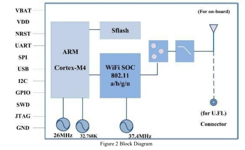
Hardware Architecture
ALX85XintegratesanARM® 32-bit Cortex®-M4micro-controller, a Wi-Fi BB/MAC/RF SoC, an RF front end, and an On-Board SPI Flashintothe small factor module.
Interface and Peripherals
The controller family includes various different host interfaces to communicate with the Host CPU.
The below table lists the basic descriptions of the MCU, Wi-Fi SoC, and interfaces.
Table 2MCU and Interfaces
| Model | ALX85X | |
| Wi-Fi Technology | IEEE802.11 a/b/g/n | |
| Frequency Band | 2.4GHz & 5GHz, Dual Band | |
| MCU | Core | ARM® Cortex®- M4 @1OOMHz |
| RAM | 128KB | |
| ROM | 512KB | |
| Flash (On-Board) | 1MB | |
| Host Interfaces | UART x 2 | Up to 6.25Mbps |
| SPI x 1 | 50MHz, multiplexing with USB & UART1 | |
| USB x 1 | UAB 2.0, Full Speed – 12Mbps | |
| Peripherals | I2C x I | Support 100KHz, 400KHz & 1MHz |
| ADC x 2 | 12 bit, 16 channel, multiplexing with GPIO | |
| GPIO x 10 | Max., multiplexing with interface & peripherals | |
Note: SPI, USBinterfacesarefor customized projects only, not for a standard product, please contact your local Blanket sales office or distributors for more information.
PIN Assignment
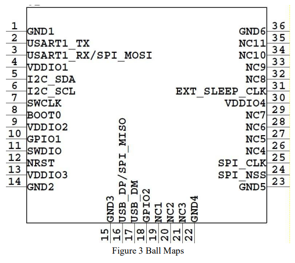
PIN Description
Table 3 PinDescriptions
| Pins | Type | Main function | Alternate functions | PIN connection (when not using ) |
| 1 | S | GND | ||
| 2 | I/O | USART1 TX | GPIO | floating |
| 3 | I/O | USART1_ RX/SPI_MOSI | GPIO | floating |
| 4 | S | VIDEO | 3.3V | |
| 5 | I/O | I2C_SDA | GPIO | floating |
| 6 | VO | I2C_SCL | GPIO | floating |
| 7 | VO | SWCLK | JACK-, SWCLK | floating |
| 8 | I | BOOT | floating | |
| 9 | V | VBA | 3.3V | |
| 10 | VO | GP101 | GPIO | floating |
| 11 | VO | SWD10 | JACK-SWD10 | floating |
| 12 | I | NRST | Active-low reset input | floating |
| 13 | V | VIDEO | 3.3V | |
| 14 | S | GND | ||
| 15 | s | GND | ||
| 16 | I/O | USB_DP/SP I_M ISO | GPIO/USARTl_RTS/USART2_RX | floating |
| 17 | I/O | USB_DM | GPIO/USART1_CTS/USART2_TX | floating |
| 18 | I/O | GPIO2 | GPIO | floating |
| 19 | floating | |||
| 20 | floating | |||
| 21 | floating | |||
| 22 | S | GO | ||
| 23 | S | GND | ||
| 24 | I/O | SPI NSS | GPIO./ADC | floating |
| 25 | I/O | SPI_CLK | GPICVADC | floating |
| 26 | floating | |||
| 27 | floating | |||
| 28 | floating | |||
| 29 | floating | |||
| 30 | V | VIDEO | 3.3V | |
| 31 | I/O | EXT_zleep_dk | Input pin for 32.768kHz or GND | |
| 32 | floating | |||
| 33 | floating | |||
| 34 | floating | |||
| E3 | floating | |||
| 56 | S | GND |
FeatureHighlights
MCU
ALX85Xfamily has a dedicated microcontroller to enhance the Wi-Fi function or applications. The MCU has anARM® 32-bit Cortex®-M4 core with FPU, adaptive real-time accelerator (ART Accelerator™) allowing 0-wait state execution from Flash memory, frequency 100MHz, memory protection unit, 125 DMIPS/1.25 DMIPS/MHz(Dhrystone2.1), and DSP instructions.
Memories
 512 Kbytes of Flash memory
128 Kbytes of SRAM
1M Bytes of Built-in Serial Flash
Wi-Fi
WLAN IEEE802.11a/b/g/n,2.4GHz & 5GHz dual band.
Flexible country code and channel configuration for the worldwide market.
Integrated WLAN CMOS power amplifier with internal power detector and closed-loop power control ensures high performance on RF sensitivity and stability.
Supports per packet RX Antenna diversity
Security
AES and TKIP in hardware for faster data encryption
WEP, WPA, and WPA2support for powerful encryption and authentication
Enterprise security: IEEE802.1X authentication includes EAP-TLS, PEAP-GTC, PEAP-MSCHAPV2.
SoftAP
SoftAP and STA can be implemented on the same hardware by switching with the specified command.
Fast SoftAP and STA switch, time <3s, no reset required.
Parameters of both SoftAP and STA can be set/read by Alinket unique ACM command.
Network Connection Indication
Indications include:
o AP connecting
o AP connected
o AP disconnected
o Server connecting(no indication because only 67ms, too short to indicate)
o Server connected
o Server disconnected
Support below two methods
o In transparent mode, through GPIO to connect LEDs, LED On –connected, LED Off disconnected, LED Flashing –connecting.
o, Report the connection status to customer Host through Alinket ACM command.
Multi-Socket of TCP/UDP
Max.4 TCP sockets + 4 UDP sockets supported to connect to different networks. Those
connections can be used for either of the below two types of services or mixed circumstances.
To connect to different servers for various cloud services.
To connect to the same server or cloud for different services such as system, event, control, and service.
The figure below describes the use of multi-socket TCP or UDP connections.

Low Power Mode
ALX85Xfamily supports low power mode to meet various industries and applications. The typical implementation is to use two GPIOs.
1st GPIOfor enter/quit low power mode
2nd GPIO to indicate the status, normal or low power mode.
Fast Network Configuration –Flashlink
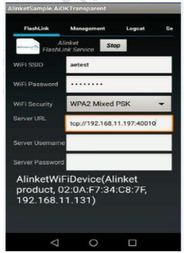 Flash link is a fast network configuration tool, especially for those ALX85Xcustomer devices without a UI display. It is an APP software that can be installed on a mobile phone or PAD. Flash link can help customers to configure the below network parameters.
AP
o Wi-Fi SSID
o Wi-Fi Password
o Wi-Fi Security
Server
o Server URL
o Server Username
o Server Password
There will be a configuration notification status in the bottom field of the configuration page.
Flash link is the industry-only Wi-Fi fast network configuration tool that supports AP and Server one-time configuration. It supports both Android and IOS.
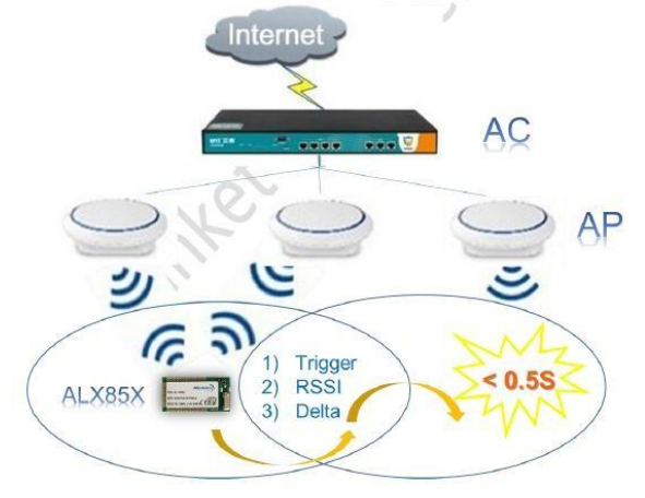
Fast Roaming
ALX85Xfamily supports fast roaming between two APs managed by the same AC. A typical
Wi-Fi roaming environments are as follows.
An AC (AP Controller) to manage the APs connected to it. The AC manages its network DHCP and equalizer.
AllAPsconnected to the above AC have the same SSID, Password, and Security (WEP, WPA or WPA2, etc.).
The IP address assigned to ALX85Xcontroller is managed by AC, not AP.
Unlike network disconnection and reconnection from one AP to another AP (usually taking 5s ~ 10s), Alinket ALX85Xis a true roaming, with its latest technology, ALX85Xroams from original AP to destination AP only take less than 0.5s period.
ALX85Xroaming technology is managed by Alinket unique ACM system. ALX85Xcontroller scans the available AP RSSI calculates the delta and triggers the roaming activity. The below figure describes the roaming mechanism of ALX85X.
ACM
ACM (Alinket Controller Message) is a message system and protocol for the communications between customer host MCU and Alinket IoT controllers. It is developed by Alinket itself and is applicable to all Alinket controllers including ALX85Xfamily.
ACM system works with the host control interfaces between customer host MCU and Blanket controllers.
Host Control Interface
The host control interfaces are used for transferring ACMmessages, Flow Control signals, and Power Save signals between customer host MCU and Alinket IoT controllers.
The below figure shows the connections between the customer host and ALX85Xfamily.
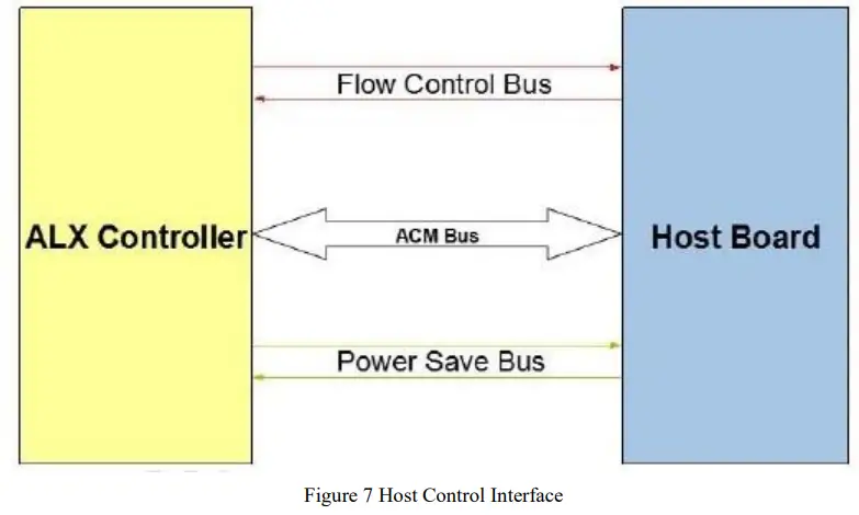
ACM Bus
ACM Bus is the interface to exchange the message between customer host MCUand Alinket controller. It can be UART, SPIinterface from a hardware point of view.
The messages include host control commands, controller command response, and alarm events from the Alinket controller as well.
Detailed message definition, the implementation of massage Flow Control and Power Save
functions can be found in documents of AlinketController Message Specification and Alinket Host Control Interface Guide. (Note: Please contact your local Alinket sales office or distributors to get the related documents.)
Wi-Fi Specification
Wireless Specification
Table 4 2.4GHz Wireless Specification
| Features | Specification |
| WLAN Standards | IEEE802.11 b/g/n |
| Antenna Port | Single Antenna |
| Frequency Band | 2.412GHz —2.484 GHz ETSI: 2412Mhz-2472Mhz FCC:2412Mhz-2462Mhz |
| Modulation | DSSS, CCK, OFDM, BPSK, QPSK, QAM |
| Support data rates | 802.11b: 1, 2, 5.5, 11(Mbps) 802.11g: 6, 9, 12, 18, 24, 36, 48, 54 (Mbps) 802.11 n: 6.5,13,19.5,26,39,52,58.5,65(Mbps) |
Table 5 5GHz Wireless Specification
| Features | Specification |
| WLAN Standards | IEEE802.11 a/n |
| Antenna Port | Single Antenna |
| Frequency Band | 5.17GHz-5.31GHz,5.490-5.835GHz
ETSI: 5180Mhz-5240Mhz FCC:5180Mhz-5240Mhz,5745Mhz-5825Mhz |
| Modulation | OFDM, BPSK, QPSK, QAM |
| Support data rates | 802.11a: 6, 9,12, 18,24,36,48,54(Mbps) 802.11 n: 6.5,13,19.5,26,39,52,58.5,65(Mbps) |
Tx Power
Table 6 2.4GHz TX Power
| RF Characteristics | TYP. | Unit |
| RF TX Power@l lb, 1Mbps | 23.0 | dBm |
| RF TX Power@11g,54 Mbps | 25.0 | dBm |
| RF TX Power@lln,65 Mbps | 25.0 | dBm |
Table 7 5GHz TX Power
| RF Characteristics | TYP. | Unit |
| RF TX Power@lla,6Mbps | 13.0 | dBm |
| RF TX Power@lln,65 Mbps | 13.0 | dBm |
Rx Sensitivity
Table 8 2.4GHz RxSensitivity
| Receiver Characteristics | TYP. | Unit |
| PER <8%, Rx Sensitivity @ 1Mbps DSSS | -95 | dBm |
| PER < 8%, Rx Sensitivity @ 11 Mbps CCK | -89 | Min |
| PER < 10%, Rx Sensitivity @ 6 Mbps OFDM | -92 | Min |
| PER < 10%, Rx Sensitivity @ 54 Mbps OFDM | _77 | dBm |
| PER < 10%, Rx Sensitivity @ MCSO | -92 | dBm |
| PER < 10%, Rx Sensitivity @ MCS7 | -73 | Min |
Table 95GHz RxSensitivity
| Receiver Characteristics | TYP. | Unit |
| PER <10%, Rx Sensitivity @ 6Mbps OFDM | -90.5 | dBm |
| PER < 10%, Rx Sensitivity @ 54 Mbps OFDM | -73.5 | dBm |
| PER < 10%, Rx Sensitivity @ MCSO | -90.5 | dBm |
| PER < 10%, Rx Sensitivity @ MCS7 | -70.5 | dBm |
Modular Usage Statement
Note 1: This module certified complies with RF exposure requirements under mobile or fixed conditions; this module is to be installed only in mobile or fixed applications.
A mobile device is defined as a transmitting device designed to be used in other than fixed locations and to generally, be used in such a way that a separation distance of at least 20 centimeters is normally maintained between the transmitter’s radiating structure(s) and the body of the user or nearby persons. Transmitting devices designed to be used by consumers or workers that can be easily re-located, such as wireless devices associated with a personal computer, are considered to be mobile devices if they meet the 20-centimeter separation requirement.
A fixed device is defined as a device that is physically secured at one location and is not able to be easily moved to another location.
Note 2: Host product manufacturers must provide in their user manual the required RF exposure information for mobile & fixed usage of this module. Host product manufacturers must use the following RF exposure statement in their user manual “This equipment complies with FCC radiation exposure limits set forth for an uncontrolled environment. This equipment should be installed and operated with a minimum distance of 20 cm between the radiator and all persons. This transmitter must not be co-location r operating in conjunction with any other antenna or transmitter.”
Note 3: Any modifications made to the module will void the Grant of Certification, this module is limited to OEM installation only and must not be sold to end-users, end-user shall have no manual instructions to remove or install the device, only software or operating procedure shall be placed in the end-user operating manual of final products.
Note 4: Additional testing and certification may be necessary when multiple modules are used.
Note 5: The module may be operated only with the PIFA Antenna with which it is authorized.
Note 6: To ensure compliance with all non-transmitter functions the host manufacturer is responsible for ensuring compliance with the module(s) installed and fully operational. For example, if a host was previously authorized as an unintentional radiator under the Supplier’s Declaration of Conformity procedure without a transmitter certified module and a module is added, the host manufacturer is responsible for ensuring that after the module is installed and operational the host continues to be compliant with the part 15B unintentional radiator requirements. Since this may depend on the details of how the module is integrated with the host, the manufacturer shall provide guidance to the host manufacturer for compliance with the part 15B requirements.
Note 7: When the FCC ID certification number is not visible when the module is installed inside another device, then the outside of the device into which the module is installed must also display a label referring to the enclosed module. This exterior label can use the wording ”Contains transmitter module FCC ID: SMQALX850BEDAN” or “Contains FCC ID: SMQALX850BEDAN”.
Note 8: The FCC rule/s for this module are CFR 47 Part 15 Subpart C.
Note 9: This modular transmitter is only FCC authorized for the specific rule parts listed on its grant. The host product manufacturer is responsible for any other FCC rules that apply to the host not covered by the modular transmitter grant of certification. The final host product will require Part 15 Subpart B compliance when the modular transmitter is installed.
FCC Warning
This device complies with part 15 of the FCC rules. Operation is subject to the following two conditions: (1) this device may not cause harmful interference, and (2) this device must accept any interference received, including interference that may cause undesired operation.
Changes or modifications not expressly approved by the party responsible for compliance could void the user’s authority to operate the equipment.
NOTE: This equipment has been tested and found to comply with the limits for a Class B digital device, pursuant to part 15 of the FCC Rules. These limits are designed to provide reasonable protection against harmful interference in a residential installation. This equipment generates uses and can radiate radio frequency energy and, if not installed and used in accordance with the instructions, may cause harmful interference to radio communications. However, there is no guarantee that interference will not occur in a particular installation. If this equipment does cause harmful interference to radio or television reception, which can be determined by turning the equipment off and on, the user is encouraged to try to correct the interference by one or more of the following measures:
- Reorient or relocate the receiving antenna.
- Increase the separation between the equipment and receiver.
- Connect the equipment into an outlet on a circuit different from that to which the receiver is connected.
- Consult the dealer or an experienced radio/TV technician for help.
Radiation Exposure Statement
This equipment complies with FCC radiation exposure limits set forth for an uncontrolled environment. This equipment should be installed and operated with a minimum distance of 20cm between the radiator and your body.
Documents / Resources
 |
Alinket ALX850X WiFi Controller Module [pdf] User Manual ALX850BEDAN, SMQALX850BEDAN, ALX850X WiFi Controller Module, ALX850X, WiFi Controller Module |


