![]()

Specifications
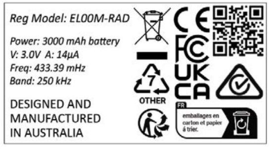
Mini VERSION 3.0
Model E-LOOP: EL00M & EL00M-RAD
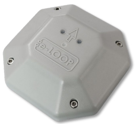
EL00M Loop Mini Wireless Loop Detection System
Step 1 – Coding e-LOOP version 3.0
Option 1. Short-range coding with magnet
- Power up the e-Trans 50, then press and release the CODE button. The blue LED on the e-Trans 50 will light up, now place the magnet on the CODE recess on the e-Loop, the yellow LED will flash, and the blue LED on the e-Trans 50 will flash 3 times. The systems are now paired, and you can remove the magnet.
Option 2. Long range coding with magnet (up to 50 Meters)
- Power up the e-Trans 50, then place the magnet on the code recess of the e-Loop, the yellow code LED will flash once now remove magnet and the LED come on solid, now walk over to the e-Trans 50 and press and release the CODE button, the yellow LED will flash, and the blue LED on the e-Trans 50 will flash 3 times, after 15 seconds the e-loop code LED will turn off .
Safety instructions
Before proceeding with the product’s installation, check that all the materials are in good working order and suited to the intended applications.
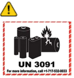
Warning! – Exhausted batteries contain polluting substances; therefore they may not be disposed of together with unsorted household waste. They must be disposed of separately according to the regulations locally in force.
Disposal
The packaging must be disposed of in the local recyclable containers. According to the European Directive 2002/96/EC on waste electrical equipment, this device must be properly disposed of, after usage in order to ensure a recycling of the materials used.
Old accumulators and batteries may not be disposed of in the household waste, since they contain pollutants and must be properly disposed of in municipal collection points or in the containers of the dealer provided. Country-specific regulations must be observed.
Step 2 – Fitting the e-LOOP Mini bases plate to the driveway
- Face the arrow on the base plate towards the gate. Using a 5mm concrete masonry drill, drill the two mounting holes 55mm deep, then use the 5mm concrete screws supplied to fix to the driveway.
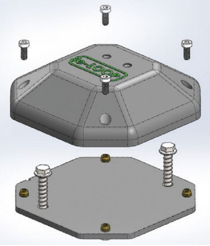
Step 3 – Fitting the e-LOOP Mini to the base plate
(Refer to the diagram on the right)
- Now fit the e-loop Mini to the base plate using the 4 hex screws supplied, making sure the arrow also points towards the gate (this will ensure the keyway is aligned). The e-Loop will become active after 3 minutes.
NOTE: Ensure hex screws are tight as this forms partof the water-sealing process.
Document updated: 26/02/2024.
Installation Warnings
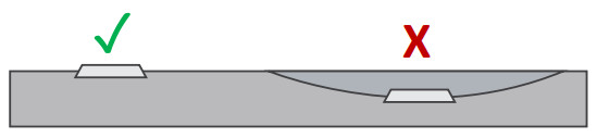
The e-LOOP should be installed in a location that is always visible. Do not place the e-LOOP in a dip or area where snow or water can sit.
Keep e-LOOP central in the driveway so that it passes directly underneath the vehicles. Bolt down e-LOOP on a flat surface, using only the supplied concrete screws or a rubberized adhesive. Do not drill screws in on an angle.
DISCLAIMER: UNITS WITH THE PRESENCE FEATURE ARE NOT TO BE USED AS A SOLE SAFETY DEVICE & SHOULD BE USED IN CONJUNCTION WITH STANDARD GATE SAFETY PRACTICES.
![]() IMPORTANT: Never fit near high voltage cables, this can affect the e-Loop’s vehicle detection and radio range capabilities.
IMPORTANT: Never fit near high voltage cables, this can affect the e-Loop’s vehicle detection and radio range capabilities.
IMPORTANT:
This product can expose you to chemicals including Acrylonitrile.
FCC WARNING
This device complies with part 15 of the FCC Rules.
Operation is subject to the following two conditions: (1) this device may not cause harmful interference, and (2) this device must accept any interference received, including interference that may cause undesired operation. Any changes or modifications not expressly approved by the party responsible for compliance could void the user’s authority to operate the equipment.
NOTE: This equipment has been tested and found to comply with the limits for a Class B digital device, pursuant to Part 15 of the FCC Rules. These limits are designed to provide reasonable protection against harmful interference in a residential installation. This equipment generates, uses and can radiate radio frequency energy and, if not installed and used in accordance with the instructions, may cause harmful interference to radio communications. However, there is no guarantee that interference will not occur in a particular installation.
If this equipment does cause harmful interference to radio or television reception, which can be determined by turning the equipment off and on, the user is encouraged to try to correct the interference by one or more of the following measures:
- Reorient or relocate the receiving antenna.
- Increase the separation between the equipment and receiver.
- Connect the equipment to an outlet on a circuit different from that of the receiver.
- Consult the dealer or an experienced radio/TV technician for help.
To maintain compliance with FCC’s RF Exposure guidelines, this equipment should be installed and operated with a minimum distance between 20cm of the radiator and your body: Use only the supplied antenna.

![]() FCC ID: 2A8PC-EL00M
FCC ID: 2A8PC-EL00M
E. sales@aesglobalus.com
www.aesglobalus.com
T: +1 – 321 – 900 – 4599
Documents / Resources
 |
AES EL00M Loop Mini Wireless Loop Detection System [pdf] Instruction Manual EL00M, EL00M-RAD, EL00M Loop Mini Wireless Loop Detection System, EL00M, Loop Mini Wireless Loop Detection System, Wireless Loop Detection System, Loop Detection System, Detection System, System |