![]() STEERING WHEEL CONTROL INTERFACE
STEERING WHEEL CONTROL INTERFACE
TO SUIT VOLKSWAGEN VEHICLES
SWVW3C
 Installation Guide
SWVW3C Steering Wheel Control Interface
The SWVW3C allows for the retention of the steering wheel controls as well as other vital features when installing an aftermarket unit into the vehicle. This interface features selectable dipswitches for dedicated applications, simply refer to the provided table for the correct configuration ensuring seamless integration.
VEHICLE APPLICATION
To Suit VOLKSWAGEN
| Amarok (2H) | 2007-2014 |
| EOS (1F) | 2011-2016 |
| Golf (Mk5,Mk6) | 2004-2013 |
| Jetta | 2006-2015 |
| Passat (B6, 3C, B7, 3C36) | 2006-2015 |
| Polo (9N, 9N3, 6R) | 2006-2014 |
| Scirocco | 2009-2014 |
| Tiguan (5N) | 2008-2014 |
| Touareg | 2004-2010 |
| Transporter T5 | 2010-2015 |
| UP! | 2012-2015 |
Vehicles with the following audio systems:
RCD200/300/310/500/510 | Audio10 (Amarok) Gamma/Beta/MFD/MCD (Passat) Vehicles with Quadlock (Fakra) Connector
KEY FEATURES
- RETAIN STEERING WHEEL CONTROL FUNCTIONALITY
- REPLACE FACTORY RADIO
- OUTPUTS FOR SPEED PULSE, PARK BRAKE & REVERSE
- SOFTWARE UPDATEABLE
- REMAPPABLE BUTTONS
PRIOR TO INSTALLATION
Installation requires a certain level of technical knowledge. Prior to installation, it is important to read the manual. Select a location for installation that is dry and free from heat sources. It is essential to use the correct tools during installation to prevent any damage to the vehicle or the product itself.
Please note that we cannot be held liable for any issues arising from improper installation.
Before proceeding with installation, disconnect the negative battery terminal and ensure the key is removed from the ignition.
WIRING KEY
| ISO CONNECTOR WIRING KEY | Purple | Right Rear Speaker + |
| Purple/Black | Right Rear Speaker – | |
| Green | Left Rear Speaker + | |
| Green/Black | Left Rear Speaker – | |
| Grey | Right Front Speaker + | |
| Grey/Black | Right Front Speaker – | |
| White | Front Speaker + | |
| White/Black | Left Front Speaker – | |
| Yellow | Permanent 12V | |
| Black | Ground | |
| Red | Ignition 12V | |
| Orange | Illumination |
| FLYING WIRE WIRING KEY OUTPUTS & RATINGS |
Pink | Speed Pulse – 0 to 12V Square Wave @ 1Hz/Kph |
| Green | Park Brake | |
| Standby Current | <3mA | |
| Purple/White | Reverse Gear – 250mA | |
| Orange | Illumination – 250mA | |
| Operating Voltage | 6V to 16V | |
| Operating Temperature | 20C to 85C *rated at 25 degrees Centigrade |
DIPSWITCH CONFIGURATION
| MANUFACTURER | SYSTEM | DIPSWITCH CONFIGURATION | CONNECTION | |||
| 1 | 2 | 3 | 4 | |||
| RESERVED | NA | OFF | OFF | OFF | OFF | SOFTWARE UPDATE MODE |
| AERPRO | Analog | OFF | OFF | ON | ON | MALE 3.5MM JACK |
| ALPINE | IR DATA | OFF | ON | OFF | OFF | MALE 3.5MM JACK |
| ANALOG SINGLE EXTEND | Analog | ON | ON | ON | ON | BROWN SWC IR |
| ANALOG SINGLE WIRE | Analog | ON | ON | ON | OFF | BROWN SWC IR |
| CLARION | IR DATA | ON | OFF | OFF | ON | MALE 3.5MM JACK |
| CUSTOM | IR DATA | ON | OFF | ON | OFF | HEAD UNIT DEPENDANT |
| GRUNDIG | IR DATA | OFF | ON | OFF | ON | BROWN SWC IR |
| JVC | IR DATA | OFF | OFF | ON | OFF | BROWN SWC IR |
| KENWOOD 1 | IR DATA | ON | OFF | OFF | OFF | BROWN SWC IR |
| KENWOOD 2 | IR DATA | ON | ON | OFF | OFF | BROWN SWC IR |
| KEY 1 / KEY 2 | Analog | OFF | ON | ON | OFF | KEY1 / KEY 2 WIRES |
| KEY 1 / KEY 2 EXTEND | Analog | OFF | ON | ON | ON | KEY1 / KEY 2 WIRES |
| PHILIPS | IR DATA | OFF | ON | OFF | ON | BROWN SWC IR |
| PIONEER 1 | Analog | OFF | OFF | OFF | ON | MALE 3.5MM JACK |
| PIONEER 2 | Analog | OFF | OFF | ON | ON | MALE 3.5MM JACK |
| SONY | Analog | ON | OFF | ON | ON | MALE 3.5MM JACK |
DIPSWITCH 5 & 6
Dipswitch 5 & 6 are reserved for vehicle specific configuration
| KEY1 and KEY2 | KEY1 and KEY2 are specifically tailored for analog learning mode-style radios. Our SWC module is designed with a resistor chain that precisely matches the required resistance for seamless compatibility with this type of head unit. |
| KEY1 and KEY2 EXTEND | This mode extends every button press to 2 seconds during the learning process. However, with rolly wheel-designed steering wheel buttons, holding for 2 seconds isn’t feasible. Our KEY1 and KEY2 extend feature addresses this by automatically prolonging each press, simplifying head unit programming even in such scenarios. Extend mode is not intended for normal use, it is only used in the teaching process. |
| ANALOG SINGLE WIRE and ANALOG SINGLE WIRE EXTEND |
This function operates similarly to KEY1 and KEY2 but transmits all unique values through the IR SWC single wire. This is crucial for compatibility with learning-style head units featuring only one learning input wire. To ensure compatibility, we’ve incorporated this feature into our steering wheel control interface, ensuring seamless operation across various head unit setups. The Analog Extend mode functions identically to its counterpart within the KEY1 and KEY2 system but transmits through a single wire. |
SWC INTERFACE
CONNECTION GUIDE
BEFORE INSTALLATION
Prior to installing the interface, it is essential to remove and disconnect the factory stereo. For guidance on this process, please refer to the vehicle owner’s manual/handbook or seek assistance from a professional.
SETTING THE DIPSWITCHES
This interface includes a set of dipswitches. Consult the dipswitch selection guide to select the appropriate configuration. To activate a dipswitch, press it downward into the ‘ON’ position. Refer to the diagram for an example of the ‘KENWOOD1’ dipswitch configuration.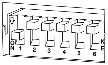
INSTALLATION
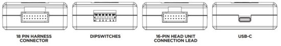
- Take the interface, then connect the 16-PIN head unit connection lead and the 18-PIN steering wheel harness connectors to their respective ports.
- Connect the head unit connection lead to the steering wheel remote input on the rear side of the aftermarket stereo. Connection methods vary based on the stereo brand, utilising either a 3.5mm jack connector SWC IR wire or wired inputs KEY1 and KEY2.
For specific connection guidance, refer to your aftermarket stereo’s installation manual if not clearly labelled on the stereo harness. - Connect the power/speaker ISO connector from the interface to the corresponding power/speaker ISO connection on the aftermarket stereo.
For aftermarket stereos lacking an ISO connector, refer to the “Wiring Key” on Page 2 for guidance on connecting wires. Certain interfaces may also
include extra “flying” wires for additional functionalities such as parking brake trigger, reverse gear, and speed pulse. Further information on these wires is available in the “Flying Wire Wiring Key” section. - Connect the vehicle-specific connectors from the interface harness to the corresponding connectors on the vehicle harness.
- Connect the flying wires on the harness to the rear of the stereo (iff applicable).
- Connect the antenna adapter to the vehicle’s existing connection at the rear of the aftermarket stereo.
- When installing an aftermarket reverse camera, connect the yellow RCA from the harness to the yellow RCA of the aftermarket camera. (If supported by the interface and vehicle)
- When installing a DAB antenna, ensure to connect the DAB aerial connector to the rear of the new stereo.
- After connecting all wires (along with any additional accessories), it’s crucial to thoroughly test the stereo and steering wheel controls before reassembling the dashboard. If steering wheel controls are unresponsive, inspect connections and check dipswitch
settings. Repeat the connection process if necessary, following the outlined steps.
STEERING WHEEL CONTROL CONFIGURATION

| A Volume Up B Volume Down C Track Up |
D Track Down E Source F Mute / Voice |
G Pick Up H Hang Up I Vehicle Menu |
The provided diagram, while meticulously researched, serves as an example only. Actual steering wheel control configurations may vary dependant on each vehicle.
The steering wheel buttons listed offer the flexibility of being re-configured or assigned dual functions. The availability of these buttons depends on the specific vehicle to which the interface is being installed and if the aftermarket radio supports them.
In addition to button remapping, we offer the option to assign dual functions to each button on the steering wheel. This means that every button can be programmed to execute both a short press command and a long press command.
You can also add your own bespoke configuration. Button configuration can be done by PC, MAC and smart phone via the USB port.
Button Remapping instructions can be found in a separate guide on our website
CONNECTION DIAGRAM
SWC VEHICLE HARNESS SWC INTERFACE
 HEAD UNIT CONNECTION LEAD
![]()
Documents / Resources
 |
Aerpro SWVW3C Steering Wheel Control Interface [pdf] Installation Guide SWVW3C Steering Wheel Control Interface, SWVW3C, Steering Wheel Control Interface, Wheel Control Interface, Control Interface, Interface |