![]()
MV-4X Multiviewer 4×2 Seamless Matrix Switcher
User Guide

https://de2gu.app.goo.gl/Wek1w2FNmyVPnojh9
This guide helps you install and use your MV-4X for the first time.
Go to www.kramerav.com/downloads/MV-4X to download the latest user manual and check if firmware upgrades are available.
Step 1: Check what’s in the box
![]() MV-4X 4 Window Multi-viewer/4×2 Seamless Matrix Switcher
MV-4X 4 Window Multi-viewer/4×2 Seamless Matrix Switcher
![]() 4 Rubber feet
4 Rubber feet
![]() 1 Power adapter and cord
1 Power adapter and cord
![]() 1 Quick start guide
1 Quick start guide
Step 2: Get to know your MV-4X

| # | Feature | Function | |
| INPUT Selector Buttons (1 to 4) | Press to select an HDMI input (from 1 to 4) to switch to output. | ||
| 2 | OUTPUT (in Matrix Mode) | Selector Button | Press to select an output. |
| LEDs (A and B) | Light green when output A or B are selected. | ||
| OD | WINDOW (in Multiview Mode) | Selector Button | Press followed by an input button to connect the selected input to a window. For example, select Window 3 and then Input button # 2 to connect input # 2 to Window 3. |
| LEDs (1 to 4) | Light green when a window is selected. | ||
| 4 | MATRIX Button | Press to operate the system as a 4×2 matrix switcher. | |
| 5 | QUAD Button | Press to display all four inputs on each of the outputs. Layouts are configured via the embedded web pages. | |
| 6 | PIP Button | Press to display one input in the background and the other images as PiP (Picture-in-Picture) over that image. Layouts are configured via the embedded web pages. | |
| 7 | MENU Button | Press to access the OSD menu, exit the OSD menu and, when in the OSD menu, move to the previous level in the OSD screen | |
| CO | Navigation Buttons | Press to decrease numerical values or select from several definitions. | |
| Press to move up the menu list values. | |||
| ► | Press to increase numerical values or select from several definitions. | ||
| Press to move down the menu list. | |||
| Enter | Press to accept changes and change the SETUP parameters. | ||
| 9 | RESET TO XGA/1080P Button | Press and hold for about 2 seconds to toggle the output resolution between XGA and 1080p, alternatively. | |
| 10 | PANEL LOCK Button | To lock, press and hold the PANEL LOCK button for about 3 seconds. To unlock, press and hold the PANEL LOCK and RESET TO buttons for about 3 seconds. |
|

| # | Feature | Function | |
| 11 | HDMI IN Connectors (1 to 4) | Connect to up to 4 HDMI sources. | |
| 12 | AUDIO OUT 5-pin Terminal Block Connector | Connect to a balanced stereo audio acceptor. | |
| 13 | HDBT | IR IN RCA Connector | Connect to an IR sensor to control a device connected to the HDBT receiver via IR Tunneling. |
| IR OUT RCA Connector | Connect to an IR emitter to control a device that is connected to MV-4X from the HDBT receiver side via HDBT tunneling. | ||
| 14 | HDBT RS-232 3-pin Terminal Block Connector | Connect to a device for RS-232 HDBT tunneling. | |
| 15 | RS-232 3-pin Terminal Block Connector | Connect to a PC to control the MV-4X. | |
| 16 | HDMI OUT A Connector | Connect to an HDMI acceptor. | |
| 17 | HDBT OUT B RJ-45 Connector | Connect to a receiver (for example, TP-580Rxr). | |
| 18 | PROG USB Connector | Connect to a USB stick to perform firmware upgrades and/or upload a Logo. | |
| 19 | ETHERNET RJ-45 Connector | Connect to a PC via a LAN | |
| 20 | 12V/2A DC Connector | Connect to the supplied power adapter. | |
The terms HDMI, HDMI High-Definition Multimedia Interface, and the HDMI Logo are trademarks or registered trademarks of HDMI Licensing Administrator, Inc.
Step 3: Mount MV-4X
Install MV-4X using one of the following methods:
- Attach the rubber feet and place the unit on a flat surface.
- Mount the unit in a rack using the recommended rack adapter (see www.kramerav.com/product/MV-4X).
 Ensure that the environment (e.g., maximum ambient temperature & air flow) is compatible for the device.
- Avoid uneven mechanical loading.
- Appropriate consideration of equipment nameplate ratings should be used for avoiding overloading of the circuits.
- Reliable earthing of rack-mounted equipment should be maintained.
- The maximum mounting height for the device is 2 meters.
Step 4: Connect inputs and outputs
Always switch OFF the power on each device before connecting it to your MV-4X.

Connecting the audio output
To a balanced stereo audio acceptor:

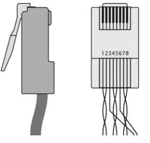
![]() For HDBT cables, it is recommended that the cable ground shielding be connected/soldered to the connector shield.
For HDBT cables, it is recommended that the cable ground shielding be connected/soldered to the connector shield.
| EIA /TIA 568B | |
| PIN | Wire Color |
| 1 | Orange / White |
| 2 | Orange |
| 3 | Green / White |
| 4 | Blue |
| 5 | Blue / White |
| 6 | Green |
| 7 | Brown / White |
| 8 | Brown |
![]() To achieve specified extension distances, use the recommended Kramer cables available at www.kramerav.com/product/MV-4X. Using third-party cables may cause damage!
To achieve specified extension distances, use the recommended Kramer cables available at www.kramerav.com/product/MV-4X. Using third-party cables may cause damage!
Step 5: Connect power
Connect the power cord to MV-4X and plug it into the mains electricity.
Safety Instructions (See www.kramerav.com for updated safety information)
Caution:
- For products with relay terminals and GPI\O ports, please refer to the permitted rating for an external connection, located next to the terminal or in the User Manual.
- There are no operator-serviceable parts inside the unit.
Warning:
- Use only the power cord that is supplied with the unit.
- Disconnect the power and unplug the unit from the wall before installing.
Step 6: Operate MV-4X
Operate Product via:
- Front panel buttons.
- Remotely, by RS-232 serial commands transmitted by a touch screen system, PC, or another serial controller.
- Embedded web pages via the Ethernet.
| RS-232 Control /Protocol 3000 | |||
| Baud Rate: | 115,200 | Parity: | None |
| Data Bits: | 8 | Command Format: | ASCII |
| Stop Bits: | 1 | ||
| Example: (Mute audio on output A): #MUTEA,1 <CR> Default Ethernet Parameters | |||
| IP Address: | 192.168.1.39 | UDP Port #: | 50000 |
| Subnet Mask: | 255.255.0.0 | TCP Port #: | 5000 |
| Gateway: | 192.168.0.1 | ||
| Default Usemame: | Admin | Default Password: | Admin |
![]()
![]()

Documents / Resources
 |
KRAMER MV-4X Multiviewer 4x2 Seamless Matrix Switcher [pdf] User Guide MV-4X Multiviewer 4x2 Seamless Matrix Switcher, MV-4X, Multiviewer 4x2 Seamless Matrix Switcher, 4x2 Seamless Matrix Switcher, Seamless Matrix Switcher, Matrix Switcher, Switcher |