1. 서론
This manual provides detailed instructions for the EBYTE M31-AXXXA000G 16DI Remote IO Module. This device is designed for industrial automation applications, supporting Modbus TCP and Modbus RTU protocols for data acquisition and control. It features an expandable design, allowing connection of up to 16 IO expansion modules to meet diverse functional requirements.
2. 제품 오버view
The EBYTE M31-AXXXA000G is a host module in the M31 series, offering 16 digital inputs (DI) and supporting both RS485 and Ethernet (RJ45) communication. It facilitates simultaneous access by up to 5 clients and supports various Modbus function codes (01/02/03/04/05/06/15/16). The module is built for reliability and ease of integration into existing Modbus systems.

그림 2.1: 앞면과 측면 view of the EBYTE M31-AXXXA000G Remote IO Module, showing its ports and indicators.

Figure 2.2: Dimensional drawing of the EBYTE M31-AXXXA000G Remote IO Module, indicating its length (110mm), width (40mm), and height (100mm).

Figure 2.3: Illustration showing multiple EBYTE Remote IO Modules connected, highlighting their modular design and expandability.
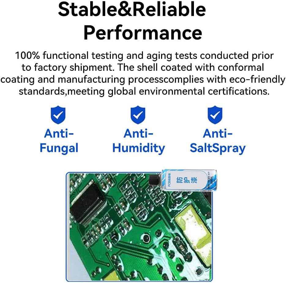
Figure 2.4: Image highlighting the module's robust design with anti-fungal, anti-humidity, and anti-salt spray properties, along with a close-up of its circuit board.
3. 설정
3.1 장착
The M31-AXXXA000G module supports installation using positioning holes or guide rails. Ensure a secure mounting location that provides adequate ventilation and protection from environmental factors.
3.2 배선 및 연결
Connect the module to your network via the RJ45 Ethernet port. For RS485 communication, connect the appropriate terminals. Ensure all power connections are correctly made according to the module's specifications.
3.3 네트워크 구성
The module supports both DHCP and static IP configurations. Refer to the specific software tools or DIP switch settings for configuring the network parameters to match your system requirements.
3.4 Modbus Address Configuration
Custom Modbus addresses can be set for the module. This can be done either through dedicated configuration software or by using the integrated dial codes (DIP switches) on the device itself.

Figure 3.1: Image depicting the DIP switches on the EBYTE M31 module for quick Modbus address configuration without a host computer.
3.5 Expansion Modules
The M31-AXXXA000G host module can connect up to 16 IO expansion modules. Ensure proper physical connection and configuration of each expansion module according to its specific instructions to extend the system's capabilities.
4. 사용 설명서
4.1 모드버스 통신
The module supports standard Modbus TCP and Modbus RTU protocols. It can be integrated with various configuration software, PLCs, and HMI touch screens. The device allows simultaneous access by up to 5 clients and supports Modbus function codes 01, 02, 03, 04, 05, 06, 15, and 16.

Figure 4.1: Diagram showing the EBYTE M31 module's compatibility with HMI touch screens, configuration software, and PLCs within a Modbus system.
4.2 Baud Rate Configuration
The module supports 8 different baud rate configurations for RS485 communication. Select the appropriate baud rate to match your connected devices for stable data transmission.
4.3 입력 범위 구성
The module's analog input ranges are configurable, making it suitable for 0-20mA and 4-20mA sensors and transmitters.

Figure 4.2: Diagram illustrating the configurable input ranges for the module, supporting both 0-20mA and 4-20mA sensors/transmitters.
4.4 Using Upper Computer Software
Utilize the dedicated upper computer software for rapid debugging and parameter configuration of the module. This software provides an interface for monitoring DI status, DO state switching, AI input acquisition, and AO output range settings.

Figure 4.3: Screenshot of the upper computer software interface, demonstrating its use for rapid debugging and parameter configuration of the EBYTE M31 series modules.
5. 유지관리
The EBYTE M31-AXXXA000G module is designed for stable and reliable performance with minimal user maintenance. It features a status diagnosis function that monitors the communication status of IO modules in real-time, aiding in system health checks.
The product undergoes 100% functional and aging tests prior to shipment. Its shell is coated with a conformal coating, providing anti-fungal, anti-humidity, and anti-salt spray properties, ensuring durability in various industrial environments.
Regularly inspect physical connections for any signs of wear or damage. Keep the module free from dust and debris to ensure optimal performance and heat dissipation.
6. 문제 해결
If you encounter issues with the EBYTE M31-AXXXA000G module, consider the following basic troubleshooting steps:
- 전원 확인: Ensure the module is receiving adequate power and that power connections are secure.
- 연결 확인: Check all Ethernet and RS485 cable connections for proper seating and integrity.
- 네트워크 설정: Verify that the IP address, subnet mask, and gateway settings are correct for your network, especially if using a static IP.
- 모드버스 주소: Confirm that the Modbus address is correctly set, either via DIP switches or software, and does not conflict with other devices on the bus.
- 전송 속도: For RS485, ensure the baud rate matches that of the connected master device.
- 상태 표시기 : Observe the module's status indicators (PWR, LINK, STA, etc.) for any error codes or abnormal behavior. Refer to the product documentation for indicator meanings.
- 소프트웨어 진단: Utilize the upper computer software's diagnostic features to monitor communication status and identify potential issues.
- 확장 모듈: If using expansion modules, ensure they are correctly connected and configured.
If the problem persists after performing these checks, consult the manufacturer's technical support.
7. 사양
| 특징 | 설명 |
|---|---|
| 상표 | 이바이트 |
| 모델 번호 | M31-AXXXA000G |
| 유형 | Remote IO Host Module |
| 디지털 입력(DI) | 16 |
| 아날로그 입력(AI) | Not applicable (for this host model) |
| 디지털 출력(DO) | Not applicable (for this host model) |
| 아날로그 출력(AO) | Not applicable (for this host model) |
| 네트워크 인터페이스 | RJ45 이더넷 |
| 직렬 포트 | RS485 |
| 지원되는 프로토콜 | Modbus TCP, Modbus RTU |
| 클라이언트 액세스 | Up to 5 simultaneous clients |
| Modbus 기능 코드 | 01, 02, 03, 04, 05, 06, 15, 16 |
| Baud Rate Configurations | 8가지 옵션 |
| IP 구성 | DHCP, 고정 IP |
| 확장 기능 | Supports up to 16 IO expansion modules |
| 환경 보호 | Anti-Fungal, Anti-Humidity, Anti-Salt Spray |

Figure 7.1: Table comparing specifications and parameters across various M31 series host and expansion modules, detailing digital inputs, analog inputs, digital outputs, analog outputs, network, and serial port options.
8. 보증 및 지원
For warranty information, please refer to the terms and conditions provided by the seller or contact EBYTE directly. Technical support and further assistance can be obtained through the official EBYTE channels or your product distributor.


