WATERLEESS M Series Multi Function Machines

លក្ខណៈបច្ចេកទេស
- Model: M SERIES R-454B
- Configurations: WG2AD (Forced air/heating/cooling with domestic water heating), WG2AH (Forced air/heating/cooling with hydronic water heating)
- ការអនុលោមតាម: UL 60335-2-40/CSA C22.2 លេខ 60335-2-40
ការណែនាំអំពីការប្រើប្រាស់ផលិតផល
ការដំឡើង៖
Ensure compliance with national, state, and local codes during installation. Follow the guidelines provided in the manual for proper installation.
Poe Oil Precaution:
- Vacuum pumps do not remove moisture from POE oil.
- Do not open the system to the atmosphere while under a vacuum.
- Wrap filter driers and service valves with a wet cloth when brazing.
នាមត្រកូលឧបករណ៍
- ឯកតាម៉ាស៊ីនបង្ហាប់
- អង្គភាពគ្រប់គ្រងខ្យល់
ការណែនាំអំពីការដំឡើង៖
- Insulate refrigerant and water lines with at least 1/2 wall thickness of Armaflex or equivalent insulation.
- Factor in all line set fittings when calculating equivalent length.
- Use the provided chart to determine fitting’s equivalent length.
Compressor Unit Placement:
- Compressor units can be located inside or outside. If outside, use a standard HVAC outdoor unit pad. If inside, place on a level, hard surface.
- Avoid placing near sound-sensitive areas of the residence.
M SERIES (Multi-Function Machines)
R-454B
WG2AD (Forced air/heating/cooling with domestic water heating) WG2AH (Forced air/heating/cooling with hydronic water heating)
ការបដិសេធ
- Proper installation and servicing of the Total Green Mfg. Heat Pump is essential to its reliable performance. All Total Green Mfg. Systems must be installed and serviced by a qualified HVAC contractor. Equipment sizing, selection and installation are the sole responsibility of the installing contractor.
- Installation of equipment on an existing copper earth loop design that does not match a current Total Green Mfg. Earth loop design is not permitted, will void all warranties on the equipment, and is the sole responsibility of the installing contractor. Installation must be made in accordance with the instructions set forth in this manual. Failure to provide installation by a qualified HVAC contractor in a manner consistent with this manual will void and nullify the limited warranty coverage for the system.
- Total Green Mfg. នឹងមិនទទួលខុសត្រូវចំពោះពិការភាព ដំណើរការមិនពេញចិត្ត ការខូចខាត ឬការបាត់បង់ ទោះជាដោយផ្ទាល់ ឬជាលទ្ធផលក៏ដោយ ទាក់ទងទៅនឹងការរចនា ការផលិត ការសាងសង់ កម្មវិធី ឬការដំឡើងផ្នែកណាមួយដែលបានបញ្ជាក់។
- រាល់ការងារក្រដាសកម្រៃជើងសារ និងការចុះឈ្មោះត្រូវតែបំពេញនៅពេលចាប់ផ្តើម ហើយត្រឡប់ទៅក្រុមហ៊ុន Total Green Mfg. សម្រាប់ការធានាពេញលេញ។
សូមចំណាំ៖ ទិន្នន័យអគ្គិសនីដែលបានផ្តល់ឱ្យនៅក្នុងសៀវភៅណែនាំនេះគឺអាចផ្លាស់ប្តូរដោយគ្មានការជូនដំណឹងជាមុន។ សូមយោងទៅលើស្លាកទិន្នន័យឧបករណ៍សម្រាប់លក្ខណៈពិសេសចុងក្រោយបំផុត។
- ឧបករណ៍នេះមិនត្រូវបានបម្រុងទុកសម្រាប់ប្រើប្រាស់ដោយមនុស្ស (រួមទាំងកុមារ) ដែលមានការថយចុះសមត្ថភាពរាងកាយ សតិអារម្មណ៍ ឬផ្លូវចិត្ត ឬកង្វះបទពិសោធន៍ និងចំណេះដឹងនោះទេ លុះត្រាតែពួកគេត្រូវបានផ្តល់ការត្រួតពិនិត្យ ឬការណែនាំអំពីការប្រើប្រាស់ឧបករណ៍ដោយអ្នកទទួលខុសត្រូវចំពោះសុវត្ថិភាពរបស់ពួកគេ។
- កុមារគួរតែត្រូវបានត្រួតពិនិត្យដើម្បីធានាថាពួកគេមិនលេងជាមួយឧបករណ៍។
ការព្រមានអំពីគ្រឿងដែលបំពាក់ដោយឧបករណ៍កម្តៅថ្ងៃ
A unit equipped with an optional Desuperheater can generate water temperatures up to 150° Fahrenheit. Water at this temperature can cause immediate and severe scalding. We recommend that when installing a unit with an optional Desuperheater, that an Anti-Scald Mixing valve be installed per the local plumbing code at the water heater. This should be set so that the water sent from the water heater is tempered down to 120° Fahrenheit.
ព្រមាន
សមាសធាតុអគ្គិសនីបន្តផ្ទាល់!
ការខកខានក្នុងការអនុវត្តតាមការព្រមាននេះអាចបណ្តាលឱ្យខូចខាតទ្រព្យសម្បត្តិ របួសផ្ទាល់ខ្លួនធ្ងន់ធ្ងរ ឬស្លាប់។ អនុវត្តតាមការប្រុងប្រយ័ត្នសុវត្ថិភាពអគ្គិសនីទាំងអស់ នៅពេលដែលប៉ះពាល់នឹងសមាសធាតុអគ្គិសនី។ វាអាចចាំបាច់ក្នុងការធ្វើការជាមួយសមាសធាតុអគ្គិសនីបន្តផ្ទាល់ កំឡុងពេលដំឡើង ការធ្វើតេស្ត សេវាកម្ម និងការដោះស្រាយបញ្ហានៃផលិតផលនេះ។
- វ៉ុលខ្ពស់tage ការផ្គត់ផ្គង់ថាមពលត្រូវតែយល់ព្រមជាមួយស្លាកសញ្ញាឧបករណ៍។
- Check that cabling will not be subject to wear, corrosion, excessive pressure, vibration, sharp edges, or any Other adverse environmental effects.
- ខ្សែភ្លើងត្រូវតែគោរពតាមលេខកូដជាតិ រដ្ឋ និងមូលដ្ឋាន។
- អនុវត្តតាមការណែនាំនៅលើដ្យាក្រាមខ្សែភ្លើងដែលមានទីតាំងនៅផ្នែកខាងក្រោមនៃគម្របឯកតា។
 ឧបករណ៍នេះត្រូវបានរចនាឡើងសម្រាប់ប្រើជាមួយទូទឹកកក R-454B ដែលមានចំណាត់ថ្នាក់ A2L ។ មានតែបុគ្គលិកដែលបានទទួលការបណ្តុះបណ្តាលក្នុងការគ្រប់គ្រងត្រឹមត្រូវនៃទូទឹកកក A2L ដោយប្រើសេវាកម្ម និងឧបករណ៍ដំឡើង A2L ដែលត្រូវគ្នាប៉ុណ្ណោះគួរតែអនុវត្តសេវាកម្ម និងការដំឡើងឧបករណ៍នេះ។ គ្រឿងបរិក្ខារនេះដឹកជញ្ជូនដោយគ្មានទូរទឹកកកជាមួយនឹងបន្ទុកផ្ទុកអាសូតស្ងួត។ ការដំឡើង និងបុគ្គលិកសេវាកម្មគឺទទួលខុសត្រូវទាំងស្រុងចំពោះសេវាកម្មត្រឹមត្រូវ និងការគិតថ្លៃឧបករណ៍នេះ ដូចដែលមានចែងក្នុងរឿងនេះ ព្រមទាំងសៀវភៅណែនាំអំពីសេវាកម្ម និងការដំឡើង Total Green Mfg ។

ព្រមាន
ហានិភ័យនៃអគ្គីភ័យ។
- ទូរទឹកកកដែលងាយឆេះត្រូវបានប្រើប្រាស់។
- ត្រូវជួសជុលដោយបុគ្គលិកសេវាបណ្តុះបណ្តាលតែប៉ុណ្ណោះ។
- កុំវាយបំពង់ទូរទឹកកក។
សេចក្តីជូនដំណឹង
- បានដំឡើងប្រព័ន្ធរកឃើញលេចធ្លាយ។
- អង្គភាពត្រូវតែត្រូវបានថាមពល លើកលែងតែសម្រាប់សេវាកម្ម។
ដំណាក់កាលទាំងអស់នៃការដំឡើងនេះត្រូវតែគោរពតាមលេខកូដជាតិ រដ្ឋ និងមូលដ្ឋាន។
សំខាន់៖ ឯកសារនេះគឺជាទ្រព្យសម្បត្តិរបស់អតិថិជន ហើយត្រូវបន្តនៅជាមួយអង្គភាពនេះ។ សូមត្រលប់ទៅកញ្ចប់ព័ត៌មានសេវាកម្មនៅពេលបញ្ចប់ការងារ។
សូមចំណាំថារូបភាពនៅក្នុងសៀវភៅណែនាំទាំងនេះគឺសម្រាប់ជាឯកសារយោងតែប៉ុណ្ណោះ ហើយប្រហែលជាមិនបង្ហាញព័ត៌មានលម្អិតទាំងអស់។ ដូចគ្នានេះផងដែរ លក្ខណៈពិសេសអាចនឹងមានការផ្លាស់ប្តូរដោយគ្មានការជូនដំណឹង។ វាជាការចាំបាច់ដែលមានតែសៀវភៅណែនាំដែលភ្ជាប់មកជាមួយឧបករណ៍ប៉ុណ្ណោះដែលត្រូវបានប្រើសម្រាប់ការដំឡើងនីមួយៗ។
![]() ឧបករណ៍នេះត្រូវបានចាត់ថ្នាក់ជាប្រព័ន្ធមួយផ្នែក ហើយត្រូវតែផ្គូផ្គងតែជាមួយឧបករណ៍ផ្សេងទៀតដែលត្រូវបានអនុម័តដោយ Total Green Mfg ដែលអនុលោមតាម UL 60335-2-40/CSA C22.2 លេខ 60335-2-40 ។
ឧបករណ៍នេះត្រូវបានចាត់ថ្នាក់ជាប្រព័ន្ធមួយផ្នែក ហើយត្រូវតែផ្គូផ្គងតែជាមួយឧបករណ៍ផ្សេងទៀតដែលត្រូវបានអនុម័តដោយ Total Green Mfg ដែលអនុលោមតាម UL 60335-2-40/CSA C22.2 លេខ 60335-2-40 ។
ការប្រុងប្រយ័ត្នប្រេង POE
- The compressor oil used in a Waterless® Geothermal system is Copeland
- Ultra 32-3 MAF. Using any other brand or type will void the manufacturer’s equipment warranty.
- POE oils absorb moisture rapidly. Do not expose oil to the atmosphere. Always flow dry nitrogen anytime a system is open to prevent the atmosphere from entering any part of the system, as it will make its way to the compressor oil. This includes line sets, earth loops, earth loop manifolds, air handlers, cased coils and any other piece of equipment that is to be connected to the refrigerant circuit. All components must be swept of atmosphere with dry nitrogen to keep the system dry when installing or servicing. Flowing dry nitrogen is not just for brazing.
- ម៉ាស៊ីនបូមធូលីនឹងមិនដកសំណើមចេញពីប្រេង POE ទេ។
- Never open a system to the atmosphere while it is under a vacuum.
- ម៉ាស៊ីនសម្ងួតខ្សែបន្ទាត់រាវត្រូវបានទាមទារ និងដំឡើងនៅគ្រប់អង្គភាពបង្ហាប់ពីរោងចក្រ។
- រុំម៉ាស៊ីនសម្ងួតតម្រង និងវ៉ាល់សេវាទាំងអស់ដោយក្រណាត់សើមនៅពេលដាក់ដែក។
- នៅពេលដែលប្រព័ន្ធត្រូវតែបើកសម្រាប់សេវាកម្ម សូមបំបែកម៉ាស៊ីនបូមធូលីបន្ទាប់ពីការស្តារទូរទឹកកកឡើងវិញជាមួយនឹងអាសូតស្ងួត ហើយតែងតែជំនួសម៉ាស៊ីនសម្ងួតតម្រង។
បញ្ជីឈ្មោះឧបករណ៍
ម៉ាស៊ីនបង្ហាប់

អង្គភាពគ្រប់គ្រងខ្យល់ 
បន្ទាត់ណែនាំការដំឡើង
- All refrigerant and water lines between these above-ground components must be insulated with at least 1/2” wall thickness Armaflex, Insul-Tube or equivalent insulation.
- រាល់ខ្សែដែលបានកំណត់ត្រូវតែត្រូវបានបញ្ចូលនៅពេលគណនាប្រវែងសមមូល។
- សូមប្រើតារាងខាងក្រោមដើម្បីគណនាប្រវែងសមមូលសមមូល។
ប្រវែងសមមូលបំពង់
- កាំវែង 90 = 3 ហ្វីត។
- ការភ្ជាប់ = 1 ហ្វីត។
- ការតភ្ជាប់ Swaged = 1ft ។
- កែងដៃ 45 ដឺក្រេ = 1.5 ហ្វីត។
ចំណាំសំខាន់៖ កែងដៃខ្លី 90° មិនត្រូវបានអនុញ្ញាតឱ្យប្រើនៅក្នុងបំពង់ណាមួយឡើយ។
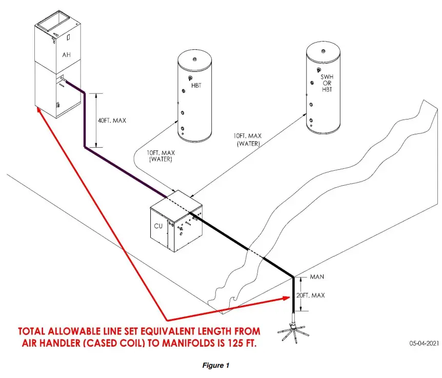 រឿងព្រេង
- CU – COMPRESSOR UNIT
- AH – AIR HANDLER ( OR CASED COIL)
- SWH – STORAGE WATER HEATER (OR TANK)
- HYDRONIC TANK
- MAN – MANIFOLDS FOR EARTH LOOPS
ការដាក់អង្គភាពបង្ហាប់
- Total Green Mfg. Compressor units may be located inside or outside. If outside, place the compressor unit on a standard HVAC outdoor unit pad. If inside, place it on a level, hard surface. If the compressor unit is to be fastened down, see Figure 2 for bracket installation.
- Avoid placing the compressor unit in or near sound-sensitive areas of the residence.
- ការបោសសំអាតជុំវិញអង្គភាពសម្រាប់សេវាកម្មត្រូវបានបង្ហាញក្នុងរូបភាពទី 3។ ទោះជាយ៉ាងណាក៏ដោយ លេខកូដក្នុងស្រុក និងបទប្បញ្ញត្តិដែលអាចអនុវត្តបានមានអាទិភាព។

 សេចក្តីណែនាំអំពីទីកន្លែងសម្រាប់គ្រឿងបរិក្ខារផ្សេងទៀតដែលបង្កើតបានជាប្រព័ន្ធ Total Green Mfg ។ ត្រូវបានដាក់បញ្ចូលជាមួយគ្រឿងបរិក្ខារទាំងនោះ ហើយត្រូវបានបញ្ចូលក្នុងកញ្ចប់ព័ត៌មាននៃសេវាកម្មអង្គភាព។
បំពង់ទូរទឹកកក
- After the Total Green Mfg. compressor unit and other system components are placed, the refrigeration system tubing is run from the compressor unit to the other components, as appropriate. Figure 4 illustrates the refrigeration and electrical connection points for the compressor unit. All pipe connections are measured in O.D.

| ច្រក | មុខងារ | ការតភ្ជាប់ | |
| A | អគ្គិសនី | រន្ធ 7/8 " | |
| B | អគ្គិសនី | រន្ធ 1-1/4 " | |
| 3 តោន | 3.5 THRU | ||
| យូនីធី | 5 តោន | ||
| តែប៉ុណ្ណោះ | UINTS | ||
| តែប៉ុណ្ណោះ | |||
| 1 | វ៉ាល់សេវារាវ AH/CC | 3/8” | ” |
| 2 | វ៉ាល់សេវារាវ Earth LOOP | 3/8” | ” |
| 3 | វ៉ាល់សេវាវ៉ាល់រង្វិលជុំផែនដី | 3/4” | 7/8” |
| 4 | វ៉ាល់សេវា AH/CC VAPOR | 3/4” | 7/8” |
| 5 | គ្មាន | ដោត | |
| 6 | គ្មាន | ដោត | |
| 7 | HX OUT | 1 1/8” | |
| 8 | HX IN | 1 1/8” | |
| 9, 10 | (OPT.) VENTS | See Leak Mitigation | |
| និង | Manual for Details on | ||
| 11 | ចេញលក់ | ||
រូបភាពទី 4. ការតភ្ជាប់
Compressor units are shipped from the factory with a dry nitrogen holding charge and Isolation Valves on all unit refrigerant line connections. DO NOT open these service valves until all brazing is complete and all connected components have been swept with dry nitrogen. Please refer back to Section 1, page 5, POE OIL PRECAUTIONS.
តម្រូវការ
ការតភ្ជាប់បំពង់បង្ហូរទឹកត្រជាក់
- សន្លាក់ទូរទឹកកកត្រូវតែស្រោបដោយលោហៈធាតុដែក 15% នៃសារធាតុប្រាក់ ដោយប្រើដំណើរការស្ងួត NITROGEN BRAZING។
ប្រយ័ត្ន!
ដំណើរការសំរឹទ្ធនីត្រូហ្សែន
- គោលបំណង៖ ប្រើប្រាស់ដំណើរការ BRAZING NITROGEN ស្ងួតនៅលើការតភ្ជាប់បំពង់ទូរទឹកកកទាំងអស់។ ដំណើរការនេះលុបបំបាត់ផលិតផលអុកស៊ីតកម្មពីខាងក្នុងផ្ទៃសន្លាក់។
- បច្ចេកទេស៖ "Trickle" ឧស្ម័នអាសូតស្ងួតនៅសម្ពាធ 1-2 psi ឆ្លងកាត់តំបន់សន្លាក់ដែលត្រូវបាន brazed ដើម្បីផ្លាស់ប្តូរអុកស៊ីសែន។ នៅពេលដែលអុកស៊ីហ្សែនត្រូវបានផ្លាស់ទីលំនៅ បិទអាសូតស្ងួត ហើយបន្ថយសម្ពាធនៅសន្លាក់ទៅនឹងបរិយាកាសមុនពេលដាក់ដែក។
- ផលវិបាក៖ ការខកខានក្នុងការផ្លាស់ទីលំនៅអុកស៊ីហ្សែនជាមួយអាសូតស្ងួតនៅសន្លាក់ដែកនឹងនាំឱ្យសារធាតុភាគល្អិតត្រូវបានបញ្ចេញទៅក្នុងប្រព័ន្ធ។ លទ្ធផលគឺការប្រែពណ៌នៃប្រេងទូរទឹកកក ការចម្លងរោគនៃប្រព័ន្ធ និងការបរាជ័យនៃប្រព័ន្ធដែលអាចកើតមាន។
!!!តម្រូវការ!!!
- Dry nitrogen should always be flowing through unit and any component and/or piping even when not brazing. This is to prevent an atmosphere that contains moisture from entering the system which will make its way to the compressor oil. This moisture cannot be vacuumed out of the oil once captured. Only the filter/drier removes this moisture.
- សូមយោងទៅផ្នែកទី 1) ទំព័រទី 5 ការប្រុងប្រយ័ត្ន POE OIL
- For field-supplied line set sizes, refer to Figure 5. Line set sizes are for both field manifolds to the compressor unit and from the compressor unit to air handler or cased coil. The line set length is from field manifolds to air handler or cased coil with the compressor being anywhere in between. Line set length cannot exceed 125 ft. For maximum efficiency, line set lengths should not exceed 100 ft. Line set lengths as stated are equivalent lengths, not actual. Fittings must be accounted for. Example: a coupling is equal to 1 ft. of line set and a long radius elbow is equal to 3 ft. of line set. In addition, never use close radius elbows in the system piping.
ប្រវែងសមមូលបំពង់
- កាំវែង 90 = 3 ហ្វីត។
- ការភ្ជាប់ = 1 ហ្វីត។
- ការតភ្ជាប់ Swaged = 1ft ។
- កែងដៃ 45 ដឺក្រេ = 1.5 ហ្វីត។
ចំណាំសំខាន់៖ Short-radius 90° elbows are NOT permitted to be used in any piping.
LINE SET PIPING AND ADAPTERS REQUIRED ARE FIELD SUPPLIED. CHECK ALL APPROPRIATE COMPRESSOR UNIT STUB-OUT TUBING SIZES FOR REQUIRED FIELD SUPPLIED ADAPTERS!
| R-454B EarthLOOP, AIR handler, CASED COIL LINE SETS | ||
|
ទំហំឯកតាម៉ាស៊ីនបង្ហាប់ |
បន្ទាត់ R-454B កំណត់ OD, អ៊ីញ |
|
|
រាវ |
ចំហាយទឹក |
|
|
3.0 តោន (-036) |
៥/៥ |
៥/៥ |
|
3.5 តោន (-042) |
៥/៥ |
៥/៥ |
|
4.0 តោន (-048) |
៥/៥ |
៥/៥ |
|
5.0 តោន (-060) |
៥/៥ |
៥/៥ |
Figure 5. Line set sizes for Units using R-454B
វ៉ាល់សេវាកម្ម
- នាវាទាំងអស់របស់អង្គភាពបង្ហាប់ Mfg. Green ទាំងអស់ជាមួយនឹងវ៉ាល់សេវាសម្រាប់វាល និងការតភ្ជាប់ឧបករណ៍ដោះស្រាយខ្យល់/ប្រអប់លេខត្រូវបានដំឡើង និងប្រហែល 75 PSIG នៃអាសូតស្ងួតនៅក្នុងអង្គភាពបង្ហាប់។ សន្ទះបិទបើកទាំងនេះត្រូវបានប្រើប្រាស់ដើម្បីញែកវាល និងឧបករណ៍ដោះស្រាយខ្យល់/ខ្សភ្លើងចេញពីអង្គភាពបង្ហាប់។ សន្ទះបិទបើកទាំងនេះត្រូវបិទរហូតទាល់តែសមាសធាតុ និងបំពង់ទាំងអស់ត្រូវបានបញ្ចប់ ហើយត្រូវបានសម្អាតដោយអាសូតស្ងួត។
- សន្ទះបិទបើកទាំងនេះត្រូវតែរុំដោយកន្ទបសើមនៅពេលដាក់ដែកដើម្បីការពារវាពីការបំផ្លាញកំដៅ។

សូមមើលសៀវភៅណែនាំដែលអាចអនុវត្តបានសម្រាប់ការដំឡើងឧបករណ៍ Total Green Mfg. ផ្សេងទៀត៖
- ជាងម៉ាស៊ីនត្រជាក់
- ខ្សភ្លើង
- ធុងទឹក។
- រង្វិលជុំផែនដី
After installing, dry nitrogen brazing and, dry nitrogen sweeping the HVAC system components, turn the Service Valves to Full Open releasing the compressor unit’s dry nitrogen charge into the rest of the system. Add additional dry nitrogen as needed to pressurize the refrigeration system to 150 psig. Valve off the dry nitrogen tank from the HVAC system components and check for leaks. Please follow the seal test procedures later in this manual.
ចំណាំ៖ ច្រកវ៉ាល់សេវាត្រូវបានបើកទៅរង្វិលជុំផែនដី និងផ្នែកម្ខាងនៃឧបករណ៏ខ្យល់/ប្រអប់លេខនៃប្រព័ន្ធ នៅពេលដែលវ៉ាល់សេវាត្រូវបានបិទ។ នេះផ្ដល់នូវមធ្យោបាយមួយដើម្បីញែកវាល និងឧបករណ៍ដោះស្រាយខ្យល់/ប្រអប់ស្រោបសម្រាប់ការសម្អាតអាសូតស្ងួត ការធ្វើតេស្តសម្ពាធ។ល។ ដោយមិនបញ្ចេញអង្គធាតុបង្ហាប់ទៅបរិយាកាស។
Storage Tanks and Water Piping
Figure 7 shows a typical water storage tank installation.
បន្ថែមសមាសធាតុអប្បបរមាដែលត្រូវការ (AS LISTED PER DIAGRAM)
ON ALL INSTALLS:
- បង្ហូរវ៉ាល់
- វ៉ាល់ ISOLATION
- ពិនិត្យវ៉ាល់
- ម៉ាស៊ីនកម្តៅ
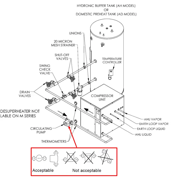
សំខាន់៖ The circulating pump must be installed with the motor shaft positioned horizontally. Under no circumstances should the pump be installed with the shaft vertical or where the shaft falls below the horizontal plane.
រូបភាពទី 7 ។ Typical WG2AD and WG2AH Primary Domestic/Hydronic Circuit Plumbing
The components are as follows:
- ម៉ាស៊ីនបូមទឹក៖ Circulating pumps, flange kits and mounting brackets are included and ship with the equipment. The design flow rate of the water circuit for the WG2AH and WG2AD should be 3 to 4 GPM per unit ton. This should be easily accomplished using the supplied circulator pump and following the piping instructions set forth in this manual. To verify the appropriate flow rate through the compressor unit heat exchanger, begin by fastening thermocouples securely on the water supply and water return copper stub outs of the compressor unit. Start the unit in heating mode. After the system has stabilized, determine the temperature differential between the supply temperature and the return temperature. The flow rate is correct if the temperature differential is 8 degrees or less. Ideally, no more than 7 degrees. If the temperature differential is higher than 8 degrees, corrections are to be made as needed to raise the flow rate.
- សំខាន់៖ The circulating pump must be installed with the motor shaft positioned horizontally. Under no circumstances should the pump be installed with the shaft vertical or where the shaft falls below the horizontal plane.
- ឧបករណ៍ត្រួតពិនិត្យសីតុណ្ហភាព៖ Digital thermostats can be provided by Total Green Mfg. These thermostats can be mounted remotely and come with a Sensor Wire 6.5 feet long.
- ធុង៖ Tanks are available through Total Green Mfg. in 80 and 119/120 US Gallon capacities, and are designed for use with Waterless® geothermal systems. These tanks can be equipped with a 4.5 kW supplemental electric heating element.
- Other Plumbing Components and Parts: Fittings, isolation valves, drain valves, strainer, unions, copper pipe, pipe insulation, etc. meeting USA industry and local code standards are commercially available through plumbing supply outlets. All elbows should be long radius and all valves should be full port.
All plumbing installations are to be in accordance with the applicable local and national codes.
- Required minimum and recommended tank capacities, flow rates and piping sizes are shown in Figure 8 for the nominal tonnage of the compressor unit specified. All field supplied tanks and piping must match what is listed.
|
Compressor Unit Model/Capacity, BTUH |
Tank Size, US Gallons |
ឈ្មោះអប្បបរមា
Type L Hard Copper Pipe & Fittings, inches |
||
| 3, 3.5 តោន
(១៤ និង ១២) |
60, 80 | 1-1/4 I.D. | ||
| 4 and 5 Ton
(១៤ និង ១២) |
80, 119/120 | 1-1/2 I.D. | ||
| ទំហំប្រព័ន្ធ | សមត្ថភាពប្រព័ន្ធ | Water Heating Flow Rate in GPM | ||
| ២២ តោន | 36,000 BTU | ពី 9 ទៅ 12 ជីពម | ||
| 3½ Ton | 42,000 BTU | ពី 10.5 ទៅ 14 ជីពម | ||
| ២២ តោន | 48,000 BTU | ពី 12 ទៅ 16 ជីពម | ||
| ២២ តោន | 60,000 BTU | ពី 15 ទៅ 20 ជីពម | ||
Figure 8. Storage Tank Capacity and Flow Rate per Unit Size
ចំណាំ៖ All water piping to be insulated with ½ inch wall pipe insulation.
Hydronic Water Heating – AH Model
(NOT to be used for Domestic Water Heating)
Hydronic Water Heating Maximum Temperature is 110°F as Measured at the Heat Exchanger Outlet
The water tank thermostat should be adjusted, regardless of the temperature shown on its display, to satisfy the call when the above condition is met. It is also recommended, for maximum efficiency, that the water temperature as measured from the water outlet of the heat exchanger be kept at 100°F or less. Your hydronic heating distribution, such as a radiant floor system, should be designed to operate at 100°F or less. If a hydronic water temperature higher than 110°F is desired, that difference in temperature should be made up with a supplemental heat source.
ការការពារប្រឆាំងនឹងការកក
- The water circulating system of a WG2AH unit must be protected from potential damage from corrosion, build-up and freeze-up by utilizing a 20% minimum of Propylene-glycol antifreeze with an Inhibitor to water solution. This antifreeze protection is provided by the installer prior to system start-up. Prior to adding glycol with an inhibitor, tank anode rods, if any, must be removed so as not to react with the glycol and inhibitor.
- Propylene glycol antifreeze solution with an inhibitor is the type of antifreeze solution required for Total Green Mfg. products utilized in radiant panel hydronic heating systems. These systems shall be freeze protected consistent with the application-specific minimum temperature as shown in the table below. Propylene-glycol antifreeze solutions should always be in the range of 20% to 50% by volume, as indicated in Figure 9.
| TEMPERATURE, °F | PROPYLENE GLYCOL, % |
| 18 | 20 |
| 8 | 30 |
| -7 | 40 |
| -៤០ | 50 |
Figure 9. Propylene Glycol Freeze Protection Table
ALWAYS REMOVE THE ANODE ROD(S) FROM THE STORAGE WATER TANK OR HEATER UTILIZED IN A RADIANT PANEL HYDRONIC HEATING IF THE ANODE ROD(S) ARE NOT REMOVED, THE PROPYLENE-GLYCOL SOLUTION WILL REACT WITH THE ANODE ROD(S) TO CREATE PARTICLES THAT BLOCK FLOW AND CAUSE SYSTEM FAILURE.
Domestic Water Heating –AD Model
(NOT to be used for Hydronic Water Heating)
Domestic Water Heating Maximum Temperature 120°F
- Please note that the maximum water temperature for the WG2AD (domestic water heating) system is 120°F as measured at the water outlet of the unit heat exchanger. This temperature is enough to satisfy most domestic water heating needs. The water tank thermostat should be adjusted, regardless of the temperature shown on its display, to satisfy the call when the above condition is met. If a higher domestic water temperature is desired, that difference in temperature should be made up with a supplemental electric element. You also have the option of sending preheated water to the cold water inlet of a standard water heater.
Filtration and Water Quality
- The inclusion of a water filter in all applications for domestic water heating is necessary. A water filter reduces the potential for silt, dirt, rust and other particulate matter from entering the heated water system. This can be achieved using a whole-house water filtration system or, at the least, a water filter on the cold water line entering the water tank.
- When specifying a system for domestic water heating, it is important to ensure that the water is not hard, and to have the water analyzed and treated as appropriate for several factors that affect the quality of potable water.
- Please refer to the applicable manual for the installation of other Total Green Mfg. equipment:
- ជាងម៉ាស៊ីនត្រជាក់
- ខ្សភ្លើង
- រង្វិលជុំផែនដី
ទិន្នន័យអគ្គិសនី និងខ្សែភ្លើងគ្រប់គ្រងវាល
ព្រមាន
សមាសធាតុអគ្គិសនីបន្តផ្ទាល់!
- Failure to follow this Warning could result in property damage, severe personal injury, or death. Follow all electrical safety precautions when exposed to live electrical components. It may be necessary to work with live electrical components during the installation, testing, servicing, and troubleshooting of this product.
- វ៉ុលខ្ពស់tage ការផ្គត់ផ្គង់ថាមពលត្រូវតែយល់ព្រមជាមួយស្លាកសញ្ញាឧបករណ៍។
- ពិនិត្យមើលថាខ្សែនឹងមិនត្រូវបានទទួលរងនូវការពាក់ ការច្រេះ សម្ពាធខ្លាំងពេក រំញ័រ គែមមុតស្រួច ឬផលប៉ះពាល់បរិស្ថានអវិជ្ជមានផ្សេងទៀត។
- ខ្សែភ្លើងត្រូវតែគោរពតាមលេខកូដជាតិ រដ្ឋ និងមូលដ្ឋាន។
- Follow instructions on the unit wiring diagram located on the bottom side of the unit lid.
សូមចំណាំ៖ ទិន្នន័យអគ្គិសនីអាចផ្លាស់ប្តូរដោយគ្មានការជូនដំណឹងជាមុន។ សូមយោងទៅលើស្លាកទិន្នន័យឧបករណ៍សម្រាប់លក្ខណៈពិសេសចុងក្រោយបំផុត។
| WG-2-XXX-D-2-XX R-454B TWO STAGE ដំណាក់កាលតែមួយ | |||||
| តោន | ដំណាក់កាលតែមួយ | អិលអេ។ | RLA | MCA | MFS |
| 3 TON {036) | ១២០ វ៉ - ៦០ ហឺត | 106 | 18.2 | 22.8 | 35 |
| 3.5 TON {042) | ១២០ វ៉ - ៦០ ហឺត | 141 | 20.1 | 25.1 | 40 |
| 4 TON {048) | ១២០ វ៉ - ៦០ ហឺត | 149 | 22.3 | 27.9 | 40 |
| 5 TON {060) | ១២០ វ៉ - ៦០ ហឺត | 166 | 28 | 35 | 50 |
| MFS = អតិបរមា Fuse ឬ HACR Circuit Breaker Size MCA = សៀគ្វីអប្បបរមា Ampទីក្រុងមួយ | |||||
| WG-2-XXX-D-2-XX R-454B TWO STAGអ៊ី ដំណាក់កាលបី | |||||
| តោន | ដំណាក់កាលតែមួយ | អិលអេ។ | RLA | MCA | MFS |
| 3 TON {036) | ១២០ វ៉ - ៦០ ហឺត | 114 | 11.5 | 14.4 | 25 |
| 4 TON {048) | ១២០ វ៉ - ៦០ ហឺត | 150 | 14 | 17.5 | 25 |
| 5 TON {060) | ១២០ វ៉ - ៦០ ហឺត | 162.3 | 19.2 | 24 | 35 |
| MFS = អតិបរមា Fuse ឬ HACR Circuit Breaker Size MCA = សៀគ្វីអប្បបរមា Ampទីក្រុងមួយ | |||||
សូមយោងសៀវភៅដៃឧបករណ៍ដោះស្រាយខ្យល់ TGM របស់អ្នកសម្រាប់តម្រូវការខ្សែភ្លើងផ្នែកឧបករណ៍គ្រប់គ្រងខ្យល់ជាក់លាក់របស់អ្នក។
- Johnson Controls A419 thermostat shown as reference. Any brand of compatible thermostat may be used. Johnson Controls A421 thermostats are available for purchase from Total Green Mfg. Be sure to match wiring and terminals to the thermostat used.


ដោយប្រើស្ថានីយ "X" និង "LA"
- Using the “X” terminal. For non-zoned single thermostat systems. Please note the “X” terminal circled in red on figure 10 on page 18. All Total Green Mfg. Waterless® Geothermal units utilize the “X” terminal along with an LED fault indicator light located above the “X” terminal on the field wiring terminal strip of the unit’s
electrical box. In the event of a system lock out, low pressure, high pressure, discharge temperature fault or,
a refrigerant leak having been detected, the “X” terminal energizes so that 24 volts can be read between ”X” and the common terminal “C”. The LED fault light will also light indicating a system lockout. The lockout circuit
is in place to protect the compressor unit from damage in the event the operating parameters of the system are out of range and, in the event of a refrigerant leak having been detected. Should a lockout occur, the system should be evaluated and, any corrections are to be made prior to placing the unit back into service. Please note that repeatedly resetting the lockout without any needed service can still result in compressor damage and may void the equipment warranty. - ស្ថានីយ "X" ក៏អាចត្រូវបានប្រើដើម្បីផ្ញើសញ្ញា "តម្រូវការសេវាកម្ម" ទៅកាន់ទែម៉ូស្តាតដែលត្រូវគ្នា។ ទែម៉ូស្តាតដែលមានមុខងារនេះជាធម្មតានឹងមានស្ថានីយ "L" ឬ "L/A" ។ សូមឡើងវិញview your thermostat manufacturer’s
installation manual for this function. Figure 11 below shows an example នៃសូចនាករតម្រូវការសេវាកម្តៅ Honeywell ។ - សូមចំណាំ៖ ប្រសិនបើប្រើប្រព័ន្ធគ្រប់គ្រងតំបន់សម្រាប់ការដាក់តំបន់ខ្យល់ដែលទាមទារឧបករណ៍បំលែងវត្ថុបញ្ជាដាច់ដោយឡែក មុខងារនេះនឹងមិនដំណើរការទេ ហើយមិនគួរមានខ្សែចូលទេ។

ដោយប្រើស្ថានីយ "LA"
- Using the “LA” terminal. Please note the “LA” terminal circled in red on figure 10 on page 18. All Total Green Mfg. Waterless® Geothermal units utilize the “LA” terminal along with an LED fault indicator light located above the “LA” terminal on the field wiring terminal strip of the unit’s electrical box. “LA” is a refrigerant leak alert signal.
- Both the compressor unit and the air handler/cased coil are equipped with A2L refrigerant leak sensors.
- If either sensor detects a refrigerant leak, the unit will go into lockout mode, disabling the compressor and backup heat source. The blower on forced air units will be activated and, the “LA” (Leak Alert) light along with the “X” (Lock Out) will turn on along with the “LA” terminal being energized with 24 volts AC. This terminal can be used as a trigger, if required by your local building codes, to set off a remote alarm and/or trigger a mechanical room exhaust fan in the event of a refrigerant leak. Please refer to the “Leak Mitigation Manual” in the unit’s service information packet for more information about leak mitigation as it applies.
សេចក្តីជូនដំណឹង
- បានដំឡើងប្រព័ន្ធរកឃើញលេចធ្លាយ។
- អង្គភាពត្រូវតែត្រូវបានថាមពល លើកលែងតែសម្រាប់សេវាកម្ម។
ព័ត៌មានឧបករណ៍ចាប់សញ្ញាលេចធ្លាយ៖ ឧបករណ៍ចាប់សញ្ញាលេចធ្លាយដែលប្រើនៅក្នុង Total Green's Waterless®
- Geothermal systems are designed for no less than a 15-year service life. Should a sensor failure occur during the life of the system, contact Total Green. Mfg. for replacement. No other sensor type or source should be considered. A sensor failure will result in the equipment staying in leak mitigation mode.
Dual Fuel Option and Thermostat Settings for the WG2Ax Units.
- WG2Ax units utilize a Smart Logic Control with built-in Dual Fuel system control. This dual fuel function must be utilized anytime the AUX/BACKUP heat source is applied prior to the indoor coil such as, a cased coil installed on the outlet of a furnace.
- When shipped, a WG2Ax unit will have a jumper wire installed across the “A” and “S” terminals as shown below.

- jumper នេះនៅតែមានសម្រាប់ឧបករណ៍ដោះស្រាយខ្យល់ស្តង់ដារជាមួយនឹងបន្ទះកំដៅប៉ុន្តែវាត្រូវតែយកចេញនៅក្នុងកម្មវិធីប្រើប្រេងឥន្ធនៈពីរដូចដែលបានពិពណ៌នាខាងលើ។ ប្រអប់ WG2A ត្រូវបានបង្ហាញសម្រាប់ជាឯកសារយោង។
- អង្គភាពនេះនឹងគ្រប់គ្រងមុខងារប្រេងឥន្ធនៈពីរ។ សូមប្រើការកំណត់ខាងក្រោមនៅក្នុងទែម៉ូស្តាតរបស់អ្នក នៅពេលប្រើមុខងារប្រេងឥន្ធនៈពីររបស់អង្គភាព។ ឧបករណ៍កម្តៅ Honeywell ត្រូវបានបង្ហាញជាឯកសារយោង។

ការដាក់បំពង់ លំហូរខ្យល់ និងការដាក់តំបន់ខ្យល់
- សរុបបៃតង Mfg. WG1A (single stagង) ប្រព័ន្ធទូរទឹកកកទៅខ្យល់ត្រូវការលំហូរខ្យល់ 400 CFM ក្នុង 5 តោន ដែលមិនលើសពី .2 អ៊ីញនៃសម្ពាធឋិតិវន្តសរុប។ សម្រាប់ WGXNUMXAx (ពីរ-stage) refrigerant-to-air systems, the same specifications are required when in second-stage ប្រតិបត្តិការ។ នៅពេលកំណត់តំបន់ខ្យល់ វាត្រូវបានណែនាំថា WG2Ax (ពីរ-stagង) ឯកតាត្រូវបានប្រើជាមួយនឹងឧបករណ៍ផ្លុំខ្យល់ដែលអាចផ្លាស់ប្តូរបានពេញលេញ។ នៅពេលកំណត់តំបន់ខ្យល់ វាត្រូវបានណែនាំថា តំបន់ទី 1 ឬធំជាងគេត្រូវមានទំហំ 70% នៃតម្រូវការលំហូរខ្យល់សរុប ហើយតំបន់ទី 2 មានទំហំសម្រាប់ 60% នៃតម្រូវការលំហូរខ្យល់សរុប។
- ការណែនាំនេះគឺដោយសារតែលក្ខណៈពិសេសដែលអាចទុកចិត្តបានដែលហៅថា "វដ្តថែទាំ" ដែលត្រូវបានរចនាឡើងនៅក្នុងគ្រឿង WG2Ax ។ បន្ទាប់ពីបួនដងជាប់គ្នាដំបូងtage calls without reaching second stage prior to satisfying the zone call, the system will run in second stage សម្រាប់ 5 នាទី។ នេះគឺដើម្បីធានាឱ្យបាននូវការត្រឡប់ប្រេងត្រឡប់ទៅអង្គភាពបង្ហាប់បានត្រឹមត្រូវសម្រាប់អាយុកាលរបស់ម៉ាស៊ីនបង្ហាប់យូរជាងមុន។
- In some instances, sizing zones as stated above may not be possible, leaving you with a small zone that may never call for second-stage or support the required air flow for the “Maintenance Cycle”. For this reason, a 24 volt signal, referred to as “Damper Override”, is provided by the “D” terminal on WG2Ax units. Terminal “D” is only energized while the unit is in the “Maintenance Cycle”. This 24-volt signal can be used to force open the largest zone of the duct system while the equipment is in the “Maintenance Cycle”. Utilizing this option requires the installation of a field-supplied SPDT relay with a 24-volt coil to isolate the zone board and air handler power supplies. The “D” terminal and relay provide a means of making the “R” and “Y” thermostat input of the zone board’s largest zone. When in the “Maintenance Cycle”, forcing that zone open relieves excessive static pressure at the air handler without the need of a bypass or dump zone. See Figure 12 for the Field Wiring Diagram for use with the damper override សញ្ញា។

ការធ្វើតេស្តត្រា
ព្រមាន!
To avoid personal injury and equipment damage, follow all safety procedures set forth by OSHA in the handling of high-pressure gases. Always use a pressure regulator and hoses that are capable of withstanding the pressures prescribed herein. Do not subject system components OTHER than the earth loop/manifold/line set configuration to 400 PSIG dry nitrogen.
- After brazing in the earth loop system (includes manifolds, earth loops and earth loop line set, but NOT the compressor unit or any other HVAC refrigeration system component), the complete underground system is to be seal tested with at least 400 PSIG of dry nitrogen. After connecting a high-pressure hose from the regulator on the nitrogen tank to a Schrader port temporarily installed on the vapor line of the line set, slowly increase the dry nitrogen pressure to no less than 400 PSIG while checking for any obvious leaks audibly.
If no audible leaks are detected, check all joints to ensure they are sealed by one of the following methods:
- ឧបករណ៍ចាប់លេចធ្លាយ Ultrasonic ឬឧបករណ៍ចាប់លេចធ្លាយដំណោះស្រាយពពុះ
- ឧបករណ៍ចាប់សញ្ញាលេចធ្លាយអេឡិចត្រូនិច (ទាមទារបរិមាណដាននៃទូទឹកកកនៅក្នុងប្រព័ន្ធ)
សំខាន់ - រង្វិលជុំត្រៀមខ្លួន
ពិនិត្យរកមើលការលេចធ្លាយដោយវិធីសាស្រ្តទាំងនេះ ឬវិធីសាស្រ្តដែលអាចទុកចិត្តបានណាមួយ ដើម្បីធានាថាមិនមានការលេចធ្លាយ ហើយប្រព័ន្ធរង្វិលជុំផែនដីត្រូវបានផ្សាភ្ជាប់! វាចាំបាច់ណាស់ដែលការផ្គុំសំណុំនៃរង្វិលជុំផែនដី / manifold / line ត្រូវបានផ្សាភ្ជាប់ទាំងស្រុងនៅមិនតិចជាង 400 psig នៃអាសូតស្ងួត។ ពិនិត្យមើលការអានឧបករណ៍ចាប់លេចធ្លាយឡើងវិញ។ លេខកូដក្នុងស្រុកអាចតម្រូវឱ្យមានសម្ពាធការធ្វើតេស្តរង្វិលជុំខ្ពស់ជាង។ គោរពតាមលេខកូដក្នុងស្រុករបស់អ្នកជានិច្ច។
- When the line set/manifolds/earth loops are deemed leak-free and sealed, valve off the nitrogen source and monitor the pressure on the underground system to ensure that at least 400 psig has been maintained for minimum of 8 hours.
- ត្រួតពិនិត្យការអានសម្ពាធក្នុងអំឡុងពេលប្រតិបត្តិការ backfilling ដើម្បីធានាថាប្រព័ន្ធរង្វិលជុំផែនដីនៅតែបិទជិត។
- សំខាន់៖ ការធ្វើតេស្តត្រាប្រព័ន្ធទាំងមូលចុងក្រោយ។
- បន្ទាប់ពីបានសាកល្បងវាលនៅមិនតិចជាង 400 PSI ដូចបានរៀបរាប់ខាងលើ នៅពេលដែលឧបករណ៍ដែលនៅសល់ដូចជាម៉ាស៊ីនបង្ហាប់ ឧបករណ៍ដោះស្រាយខ្យល់ ឬប្រអប់លេខ ETC ត្រូវបានដំឡើង ហើយសន្ទះបិទបើកម៉ាស៊ីនប្រព័ន្ធទាំងមូលគួរតែត្រូវបានដាក់សម្ពាធដល់ 150 PSI ហើយទុកឱ្យឈរមួយនាទី។ 8 ម៉ោងសម្រាប់ការធ្វើតេស្តត្រាប្រព័ន្ធសរុប។
- Please refer to your Vacuum and Charging procedures manual in your unit’s service packet for startup
- If you have any questions regarding these procedures, please contact Total Green
- Mfg. technical support at ៨៦៦-៤៤៧-២១៩៤.
សំខាន់!
- If any specifications in this manual cannot be met, contact Total Green Mfg. for a possible solution and approval. Any approved solutions that differ from the specifications in this manual must be approved with a written variance from Total Green Mfg.
ដ្យាក្រាមខ្សែភ្លើងឯកតា
WG2AD With Out Sure Start, Single phase, 230 Volts

WG2AD With Sure Start, single phase, 230 Volts

WG2AD three phase, 230 Volts

WG2AH Without Sure Start

WG2AH With Sure Start

WG2AH three-phase
- គ្រោងការណ៍អគ្គិសនី
- VG2ÅH-xxD2___
- 230V, THREE PHASE* 60HZ
- C11-19-e0242

Generic Distribution Piping, Tank and Design Examples, WG2AH only


Domestic Hot Water WG2AD units only.

ប្រយ័ត្ន៖ IF BUILDING COLD WATER SUPPLY HAS A BACK-FLOW PREVENTER. CHECK VALVE OR WATER METER WRH CHECK VALVE. PROVISIONS FOR THERMAL EXPANSION OF WATER IN THE HOT WATER SYSTEM MUST BE PROVIDED.

Installer Function Options, Jumper Wires

- Shown on the top, the AD unit, forced air heating and cooling with 100% domestic hot water on demand, ships with a jumper wire across terminals “R” and “AW”. With this jumper installed, air heating and cooling take priority over water heating. Given the fast recovery time for water heating, we recommend removing this jumper to prioritize water heating for most installations. Please note the “N” on the input strip. This is the water tank thermostat call.
Shown below the AD unit, the AH unit, forced air heating and cooling with hydronic diverting circuit, has the following terminals and features:
- Please note the “N” on the input strip. This is the water tank thermostat call.
- Please Note the “SZ”, “R”, and “AW” . These are your function option terminals.
- Units are shipped with a jumper wire across terminals “R” and “AW”. This prioritizes the forced air call over the water heating call. Removing the jumper prioritizes the water heating call over the forced air call.
- Split Zoning: The “SZ” terminal (Split Zone) allows the unit to heat one zone or floor with hydronic heat and another zone or with forced air. “Split Zone” is active by removing the priority call jumper making hydronic water heating the priority over air, and jumping “R” to the Split Zone “SZ) terminals of the field wiring terminal block. In this mode, while the unit is heating water for the hydronic zone, any “Y” call for heating in the forced air zone is shifted to the Auxiliary heating “W” Terminal. After the call completes, the unit resumes normal operation.
Examples of when air heating should be a priority over hydronic water heating:
- When radiant floor heat is not the primary heat source, such as floor tempering, meaning just enough heat to not have cold floors, such as in a Master Bath or areas of the home with tile or hardwood floors.
- When the radiant floor system uses tubing spacing or lengths of tubing requiring water temperatures above 110°F to deliver adequate heat, to be the primary heat source. In this case, the radiant floor system is just tempering the floor.
- When heating set-backs are used and fast recovery times are required.
- When Split Zoning is not used.
ប្រសិនបើអ្នកមានសំណួរទាក់ទងនឹងនីតិវិធីទាំងនេះ សូមទាក់ទងផ្នែកជំនួយបច្ចេកទេស Total Green Mfg ៨៦៦-៤៤៧-២១៩៤.
សំណួរគេសួរញឹកញាប់
Q: Can the compressor unit be placed indoors?
A: Yes, the compressor unit can be placed indoors on a level, hard surface.
Q: How should refrigerant and water lines be insulated?
A: Insulate all lines with at least 1/2 wall thickness of Armaflex or equivalent insulation.
ឯកសារ/ធនធាន
 |
WATERLEESS M Series Multi Function Machines [pdf] ការណែនាំអំពីការដំឡើង WG2AD, WG2AH, M Series Multi Function Machines, M Series, Multi Function Machines, Function Machines, Machines |