1. សេចក្តីផ្តើម
The ATO Load Cell Junction Box is designed to sum signals from multiple load cells, typically used in weighing systems such as electronic truck scales and hopper weighers. This device features a robust aluminum alloy casing, providing excellent anti-interference capabilities and an IP67 protection rating for waterproof and dustproof performance. It is equipped with 4 inlets for individual load cells and 1 outlet for the summed signal, making it easy to assemble and debug.
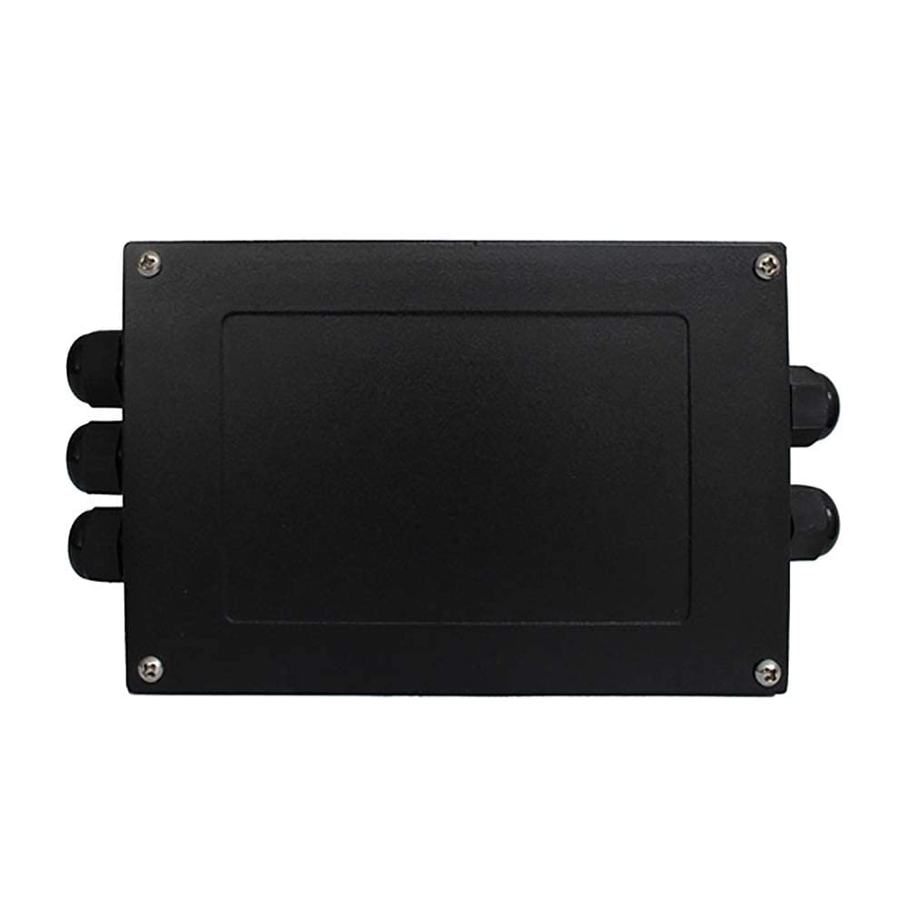
Figure 1: ATO Load Cell Junction Box (Top View)
This image shows the exterior of the ATO Load Cell Junction Box, a black rectangular aluminum alloy casing with cable glands on the sides for secure cable entry and exit.
២.១. លក្ខណៈសំខាន់ៗ
- Multi-channel Input: Features 4 inlets for connecting individual load cells.
- លទ្ធផលតែមួយ៖ Provides 1 outlet for the combined load cell signal.
- សំណង់រឹងមាំ៖ Made with an aluminum alloy casing for good anti-interference.
- ការការពារបរិស្ថាន៖ Equipped with special waterproof sealing joints and dustproof rubber gaskets, achieving an IP67 protection class.
- Easy Adjustment: Each channel includes adjustable balance potentiometers to prevent sensor damage from inductive lightning and surge signals.
- ភាពត្រឹមត្រូវខ្ពស់៖ Achieves an accuracy of ±0.1%FS.
3. មាតិកាកញ្ចប់
Please verify that all items are present and undamaged upon opening the package.
- 1 x ATO Load Cell Junction Box (Model: ATO-LCJBX-JXH-S4)
- (No additional accessories or manuals are typically included, as per product information.)
4. ការដំឡើងនិងការដំឡើង
Proper installation is crucial for the accurate and reliable operation of the load cell system. Ensure power is disconnected from all components before beginning installation.
4.1 ការដំឡើងរាងកាយ
- Mount the junction box in a secure location, preferably close to the load cells to minimize cable length and signal interference.
- Utilize the mounting holes on the casing for stable attachment to a flat surface.
- Ensure the environment is suitable for IP67 rated equipment, protecting it from excessive moisture or dust beyond its rating.

Figure 2: Load Cell Junction Box Dimensions
This diagram provides the physical dimensions of the junction box in millimeters, including length, width, and height, along with the spacing of mounting holes.
4.2 ខ្សែភ្លើង
The junction box is designed for 4 load cell inputs and 1 summed output. Refer to the wiring diagram below for correct connections.

Figure 3: Load Cell Junction Box Wiring Diagram
This diagram illustrates the internal circuit board with terminal blocks, showing connections for four load cells (LC1, LC2, LC3, LC4) to the left side and the single output connection to the right. Wire colors (Black, White, Green, Red) are indicated for both input and output, corresponding to common load cell wiring standards (e.g., Black for -EXE, White for -SIG, Green for +SIG, Red for +EXE, and SHILD for shield).
- Open the junction box cover by unscrewing the four corner screws.
- Feed the cables from each load cell through the designated cable glands (inlets) on one side of the box.
- Connect the wires from each load cell to the corresponding terminals (LC1, LC2, LC3, LC4) on the internal PCB. Ensure correct polarity:
- ខ្មៅ៖ -EXE (Excitation Negative)
- ស៖ -SIG (Signal Negative)
- បៃតង៖ +SIG (Signal Positive)
- ក្រហម៖ +EXE (Excitation Positive)
- SHILD: ខែល (ដី)
- Feed the output cable through the cable gland (outlet) on the opposite side of the box.
- Connect the output cable to the "1 Outlet" terminals on the PCB, matching the wire colors/functions as indicated in the diagram. This output will connect to your weighing indicator, transmitter, or PLC.
- Tighten all cable glands to ensure a waterproof and dustproof seal.
- Close the junction box cover and secure it with the screws.

រូបភាពទី ២៖ ផ្ទៃក្នុង View នៃ Junction Box
This image displays the open junction box, revealing the internal circuit board with terminal blocks for connecting load cells and the output, along with potentiometers for individual channel adjustments.
5. សេចក្តីណែនាំប្រតិបត្តិការ
The junction box functions as a passive summing device for load cell signals. Its primary operation involves signal combination and balance adjustment.
5.1 Signal Summing
Once all load cells are correctly wired, the junction box combines their individual electrical signals into a single output signal. This combined signal represents the total force or weight measured by all connected load cells.
5.2 Balance Adjustment (Debugging)
Each load cell input (LC1, LC2, LC3, LC4) on the PCB has an associated potentiometer (small blue adjustable resistors). These potentiometers are used to balance the output of each individual load cell, compensating for slight variations in their sensitivity or initial zero offset. This ensures that the summed signal is accurate and that the system provides consistent readings across the entire weighing platform.
- To adjust, apply a known, stable load (or no load for zero balance) to the weighing system.
- Using a small screwdriver, carefully turn the potentiometers for each load cell input. Observe the reading on your weighing indicator or display.
- Adjust each potentiometer incrementally until the system provides a stable and accurate reading, or until the zero point is correctly set when no load is applied.
- This process may require iterative adjustments to achieve optimal balance across all load cells.
6. ការថែទាំ
The ATO Load Cell Junction Box is designed for low maintenance due to its robust construction and IP67 rating. However, periodic checks are recommended to ensure optimal performance.
- ការត្រួតពិនិត្យមើលឃើញ៖ Periodically inspect the casing for any signs of physical damage, corrosion, or loose cable glands.
- ភាពសុចរិតនៃខ្សែ៖ Check all connected cables for wear, fraying, or damage. Ensure connections remain secure.
- អនាម័យ៖ If operating in a dusty environment, occasionally wipe down the exterior of the box to prevent accumulation that could compromise seals. Do not use harsh chemicals.
- ការត្រួតពិនិត្យត្រា៖ Ensure the waterproof and dustproof rubber gaskets on the cover and cable glands are intact and properly seated.
7. ការដោះស្រាយបញ្ហា
If you encounter issues with your load cell system, consider the following troubleshooting steps related to the junction box:
| បញ្ហា | មូលហេតុដែលអាចកើតមាន | ដំណោះស្រាយ |
|---|---|---|
| Inaccurate or Unstable Readings |
|
|
| គ្មានលទ្ធផលសញ្ញា |
|
|
| Water or Dust Ingress |
|
|
8. លក្ខណៈបច្ចេកទេស
| គុណលក្ខណៈ | លម្អិត |
|---|---|
| លេខម៉ូដែល | ATO-LCJBX-JXH-S4 |
| ម៉ាក | អាតូ |
| សម្ភារៈ | អាលុយមីញ៉ូម Alloy |
| ពណ៌ | ខ្មៅ |
| រចនាប័ទ្ម | បង្រួម |
| ប្រភេទបញ្ចប់ | ម្សៅស្រោប |
| ច្រកចេញចូល | 4 (for load cells) |
| ច្រកចេញ | 1 (summed signal) |
| ភាពត្រឹមត្រូវ | ± 0.1% FS |
| ថ្នាក់ការពារ | IP67 (មិនជ្រាបទឹក និងធូលី) |
| វិមាត្រកញ្ចប់ | 10.51 x 5.16 x 1.97 អ៊ីញ |
| ទំងន់ធាតុ | 1.59 ផោន |
9. ការធានា និងការគាំទ្រ
ATO is committed to providing quality products and customer satisfaction. While specific warranty details are not provided in this manual, general support is available.
- For any questions, concerns, or issues regarding the product or its operation, please contact ATO customer service.
- You can typically reach support via email, and responses are generally provided within 12 hours.
- Please refer to the product listing or ATO's official website for the most current contact information and warranty policy.


