 Kele KGD-BACNET Multi Protocol Adapter
Kele KGD-BACNET Multi-protocol RS-485 Adapter
Specifications:
- Protocol: BACNET
- Interface: RS-485
- Compatibility: Multi-protocol
User Instructions:
General Safety Information
Always refer to the user instructions for safety guidelines.
List of Warnings:
Ensure proper grounding before installation. Do not expose to water or extreme temperatures.
Use Instructions and Limitations
- Use For:
The Kele KGD-BACNET Adapter is designed for integrating BACNET protocol devices. - Do NOT use for:
Do not use the adapter for protocols other than BACNET. - Features:
The adapter supports multi-protocol communication and RS-485 interface. - Specifications:
Detailed specifications can be found in the user manual on page 7.
Installation Instructions
- Location
Choose a suitable location away from moisture and extreme temperatures. - Installation
Follow the installation steps provided in the user manual on page 8. - Connection
Connect the adapter as per the wiring instructions on page 10.
Wiring
- Signal Wire: Refer to page 11 for details.
- Topology: Follow the recommended topology on page 11.
- Length: Ensure wiring length complies with guidelines on page 12.
- Grounding: Proper grounding instructions on page 12 must be followed.
- Power Wire: See page 13 for power wire connections.
Configuration
Kele NPU Software
Utilize the Kele NPU software for configuration, details provided on page 15.
Addressing and Communication Settings
Configure addressing and communication settings as per instructions on page 16.
Firmware and Configuration Update
For firmware and configuration updates, refer to page 18 of the user manual.
FAQ:
- Q: Can I use this adapter for protocols other than BACNET?
A: No, this adapter is specifically designed for BACNET protocol devices and should not be used for other protocols. - Q: What is the recommended installation location for the adapter?
A: Choose a location away from moisture and extreme temperatures to ensure optimal performance.
General Safety Information
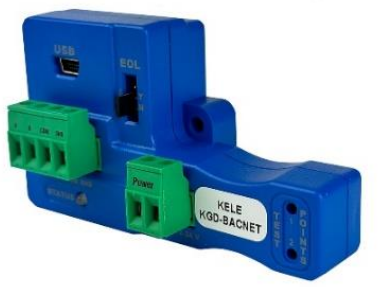
The Kele KGD-BACNET Adapter is an accessory used to convert the 4-20mA analog signal from Kele 6-Series type detectors to a digital signal for use with multipoint addressable systems. The Kele KGD-BACNET simply connects to the back of the detector and a single screw fastens it in place. The KGD-BACNET accepts the 4-20mA output and is powered from the same connection as the detector. The KGD-BACNET can interface with Building Automation Systems, Control Panels or other Control Devices that accept Modbus, BACnet, Metasys and Siemens communication protocol.
List of warnings
WARNING
- Each person using this equipment must read and understand the information in this user manual before use. Use of this equipment by untrained or unqualified persons or use that is not in accordance with this user manual, may adversely affect product performance.
- This equipment may not function effectively below 0°F or above 125°F (-18°C or above 52°C). Using the detector outside of this temperature range may adversely affect product performance.
- Do not disassemble unit or attempt to repair or modify any component of this instrument. This instrument contains no user serviceable parts, and substitution of components may impair product performance and void product warranty.
Use Instructions and Limitations
WARNING
Each person using this equipment must read and understand the information in this user manual before use. Use of this equipment by untrained or unqualified persons or use that is not in accordance with this user manual, may adversely affect product performance.
Use For
The Kele KGD-BACNET Adapter converts the Kele 6-Series 4-20mA analog output to a digital output for use with addressable network systems. The Kele 6-Series is a family of fully programmable, low voltage, dual relay gas detectors, controllers and transducers for BAS, HVAC and Fire & Security applications. The 6-Series detectors are used to measure the concentration of various gases and provide feedback and automatic control to help ensure a safe environment: Carbon Monoxide, Methane, Propane, Hydrogen, Nitrogen Dioxide and other gases.
Do NOT use for
The KGD-BACNET is not intended for use in hazardous locations or industrial applications such as refineries, chemical plants, etc. Do not mount the KGD-BACNET where the normal ambient temperature is below 0°F or exceeds 125°F (- 18°C or above 52°C). The KGD-BACNET mounts to a Kele 6-Series detector installed on a 4” x 4” electrical box electrical box supplied by the contractor.
Features
- The Kele KGD-BACNET interfaces the detector power and 4-20mA output lines with a mounted connector
- The KGD-BACNET monitors sensor type, gas level and trouble status communications from any of the Kele 6-Series detectors
- Supports Modbus, BACnet, Metasys and Siemens communication protocol.
- Communication is on a serial line with a “Two-Wire” electrical interface in accordance with EIA/TIA-485 standard using RTU Transmission Mode
- Commercial type enclosure to protect and support the electronics
- Tricolor LED indicates power, test and communication status
- Mounts behind the detector inside of a standard 4” x 4” electrical box
- Held in place on the back of the 6-Series detector with a single screw
- USB connection to configure address and communication protocol and settings.
- RS-485 termination uses 3 pin connectors with jumper to select termination: The user selects no termination or 120 Ohm termination.
- Communications connections include signal (A and B), Common and shield terminals
- Intended for use in non-hazardous areas such as parking garages, warehouses, or other commercial facilities
Specifications
- Power & Current (without detector): 1.5W (max) from 12 to 24 VAC or VDC.
- Shipping Weight: 0.25 lb (0.11 kg)
- Size: 3 1/2 x 2 x 1 3/4 in. (8.9 X 5.1 X 4.4 cm)
- Operating Environment: 14°F to 122° F (-10°C to +50°C), 20 to 90% RH non-condensing
- Connections: plugs/terminals
- Color: Blue
- Mounting screw and screwdriver included
- KGD-BACNET operates as Modbus RTU Slave, BACnet MSTP Server, Metasys N2 Slave or Siemens FLN Slave
- Baud Rate:
- Modbus: 2400, 4800, 9600, 19200 (default), 38400, 57600, 115200 bps
- BACnet: 9600, 19200, 38400 (default), 57600, 76800, 115200 bps
- Metasys N2 Slave: 9600
- Siemens FLN Slave: 2400, 4800, 9600, 19200 (default), 38400, 57600, 115200 bps
- Parity:
- Modbus: Odd, Even (default) and None
- BACnet: No Parity
- Metasys: No Parity
- Siemens: No Parity
Installation Instructions
The following instructions are intended to serve as a guideline for the use of the Kele KGD-BACNET Adapter. It is not to be considered all-inclusive, nor is it intended to replace the policy and procedures for each facility. If you have any doubts about the applicability of the equipment to your situation, call Technical Support at 877-826-9045.
WARNING
This equipment may not function effectively below 0°F or above 125°F (-18°C or above 52°C). Using the detector outside of this temperature range may adversely affect product performance.
Location
Refer to the user instructions of the specific Kele 6-Series gas detector to which the KGD-BACNET will be connected.
Installation
The Kele KGD-BACNET Adapter converts the Kele 6-Series 4-20mA analog output to a digital output for use with addressable network systems. The Kele 6-Series is a family of fully programmable, low voltage, dual relay gas detectors, controllers and transducers for BAS, HVAC and Fire & Security applications. The 6-Series detectors are used to measure the concentration of various gas and provide feedback and automatic control to help ensure a safe environment: Carbon Monoxide, Methane, Propane, Hydrogen, Nitrogen Dioxide and other gases.
- Remove the 4-20mA/Power connector from the Kele 6-Series gas detector.
- Plug the KGD-BACNET adapter into the empty 4-pin socket.
- Install the provided KGD-BACNET screw.
- See the wiring diagram for wire connection.

- The KGD-6-Series detector mounts on a 4”x 4” electrical box supplied by the contractor.
- Connect the detector to the control cables with terminal plugs. When making connections, make sure the power is off.
- There are two terminals for the dry alarm relay contacts, again with no polarity preference. The alarm relay can switch up to 0.5 A 120 V, or 60 VA. The alarm relay is activated if gas reaches or exceeds the alarm settings. See Operation of the detector User Instructions for details on relay settings.
- The alarm relay can be configured to normally open (default) (N.O.) or normally closed (N.C.) and will activate if the gas concentration exceeds alarm set point. It will deactivate once the gas concentration drops below the alarm set point. Note that the “disable” setting will cause the alarm relay not to engage at all.
- The dry contact, SPDT fan relay has three terminals: The Common (COM), normally open (N.O.) and the normally closed (N.C.) contact. The fan relay can switch up to 5.0 A up to 240 VAC. See Operation section of the detector User Instructions for details on relay settings.
Connection
The Kele KGD-BACNET output is connected via a four-terminal screw type connector. The KGD-BACNET adapter is wired in the standard 2W-Modbus circuits definition with selectable built-in terminating resistors at the ends of the RS-485 bus. The power for the KGD-BACNET adapter is connected via a two-terminal screw type connector, 12 to 24 VAC or 12 to 24 VDC and no polarity.
Note: Running the Modbus cable adjacent to or in the same conduit with high voltage wires is not recommended as there may be interference from the high voltages. Line polarization should not be required for the KGD-BACNET but may be required for other devices on the RS-485 line – see manufacturer’s directions. 
Wiring
Signal Wire
A serial Line Cable should be shielded for best performance. The shield should be connected on each detector at SHD terminal and connected to a ground terminal or chassis only at one end of the bus. An RS-485 must use a balanced pair (for A & B) and a third wire (for the Common). For RS-485, Wire Gauge must be chosen sufficiently wide to permit the maximum length (1,000m or 3,281ft). AWG 24 is always sufficient for the Data. Category 5 cables may operate for RS-485, to a maximum length of 600 m 1968.5 ft. For the balanced pairs used in an RS- 485-system, wire with a characteristic impedance of higher than 100 Ohms may be preferred, especially for 19200 and higher baud rates.
Note: It is recommended to always use twisted wires to reduce noise and allow for reliable data communication over greater distances. Use at least 3-conductor wire with one twisted pair providing a pair for signal (A & B) and Common (COM) connections.
For best performance use shielded 3-conductor wire with one twisted pair providing a pair for signal (A & B), Common (COM) and shield ground (SHD) connections.
Topology
An RS-485 configuration without repeater has one trunk cable, along which devices are connected, directly (daisy chaining) or by short derivation cables. The trunk cable, also named “Bus”, can be long. Its two ends must be connected on Line Terminations. (see Line Termination – End of Line Resistor section). The use of repeaters between several RS-485 is also possible.
 Length
The end-to-end length of the trunk cable must be limited. The maximum length depends on the baud rate, the cable (Gauge, Capacitance or Characteristic Impedance), the number of loads on the daisy chain, and the network configuration (2-wire). For a maximum 9600 Baud Rate and AWG26 (or wider) gauge, the maximum length is 1000m 3281ft. The derivations must be short, never more than 20m 65.5ft. If a multi-port tap is used with n derivations, each one must respect a maximum length of 40m 131ft divided by n.
Grounding
The Common circuit (COM) must be connected directly to protective ground, preferably at one point only for the entire bus.
Power Wire
All field wiring is completed via modular connectors (provided). After wiring, simply plug the modular connectors into the matching connectors on the KGD-BACNET. The power connections to the remote mounted detectors should be size AWG18 (minimum) for short runs. Since Kele detectors are rated for operation between 12 and 24 VDC or VAC, the voltage drop between the power supply and the KGD-BACNET should not be an issue if the recommended power wire gauge guidelines below are followed. The terminals will accept wire from 16 to 28 AWG. To install a wire, strip back approximately 0.25 in. (6 mm) of insulation and insert the bare wire into the terminal. Tighten the screw clamp and ensure that the wire cannot be easily pulled from the connector.
| Wire gauge | Feet | Meters |
| 18 | 500 | 152 |
| 16 | 800 | 244 |
| 14 | 1250 | 381 |
Table 3-1 Power Wire lengths
Configuration
 Kele NPU Software
Kele Network Parameter Utility software can be used to set the KGD-BACNET to desired address, change the communication protocol and communication settings. This software can also be used to update KGD-BACNET with any latest firmware release from Kele. Figure 4.1 shows the screen of NPU software when a device is connected. As shown in the Figure, it displays the device name (KGD-BACNET) with device configuration version (V1.0DS) under it. Fields greyed out are read-only. Protocol- Factory default for this field is BACnet. Click on drop down list to select appropriate communication protocol. Modbus, BACnet, Metasys and Siemens are protocol supported by KGD-BACNET. Address – The address of the device in the network. This setting is not available for BACnet.
MAC Address: Defines the address (0-127) that the KGD-BACNET (node) will reside on the network. This setting is available for BACnet only.
- Baud Rate – Baud rate of the network.
- Parity – Parity for the communication.
- Response Delay: Time in milliseconds that the driver waits before responding to master requests. If no delay is required, setting this field to 0 instructs the driver to send its response as soon as possible. This setting is not available for BACnet.
- APDU Timeout – The time in milliseconds that the driver will wait for a response from a device after sending a request. This setting is available for BACnet only.
- Several APDU Retries – The number of times the driver will retry a request when a response is not received. This setting is available for BACnet only.
- Device Name: Device name that will appear for KGD-BACNET in BACnet network. The device name must be unique across the entire BACnet network. Enter a string of between 1 and 16 characters long. This setting is available for BACnet only.
- Device Instance: Object Instance for KGD-BACNET device BACnet object. The instance number must be unique across the entire BACnet network. Valid entries are between 0-4194302. This setting is available for BACnet only.
- Max Master: Defines the highest allowable address (0-127) for MS/TP master nodes on the network. Any address higher than this will not receive the token from the unit. Note that this value must be greater than or equal to the configured MAC Address(es). If the highest address on the network is unknown, set this field to 127. This setting is available for BACnet only.
Addressing and Communication Settings
Connect KGD-BACNET to PC using mini USB to USB adapter, and open Kele NPU software. Kele NPU software will display the current settings of the KGD-BACNET. Update the settings in Kele NPU software and hit Submit to load the updated settings into KGD-BACNET. Footer of the NPU software displays the status of the settings update.  NOTE: After any configuration change, disconnect the USB cable from KGD-BACNET and perform power reset for KGD-BACNET.
Following table shows the valid addresses for different protocols.
| Communication Protocol | Valid Address |
| Modbus RTU | 1…247 |
| BACnet MS/TP | 0…127 |
| Metasys N2 | 1…255 |
| Siemens FLN | 1…98 |
Table 4-1
Firmware and Configuration Update
To receive the latest version of Kele NPU, as well as firmware and configurations, download the Kele NPU from our website http://www.Kele.com/downloads.html. If a newer version of firmware is available in the NPU you will be prompted to update when connected to the KGD-BACNET. Kele NPU Folder downloaded from website contains a file “KGD-BACNET_VXXX.DUF” where VXX is the version number. This file is the configuration file for different communication protocol supported by KGD-BACNET. This configuration file can be uploaded to KGD-BACNET using following procedure.
- Open the Kele Network Parameter Utility Software.
- If KGD-BACNET is connected to PC via USB, the software will display home screen like one in Figure 5-1. If Software does not detect the KGD-BACNET it will display “No Device Connected”. Make sure software detects the panel before proceeding.
- Go to File (on the top left corner of the software) and select “Update Device…”.
- A new window will pop up to select the file. Select the DUF file and hit Open.
- Now the DUF file will be loaded into the panel. The progress of the file update is displayed at the bottom.
 Once the update is complete it will reset the device and it will return to home screen. Verify the correct version of the device configuration file is updated. Device configuration version is displayed alongside the product image displayed in NPU software. It has format “Multi-Protocol VX.XX” where X.XX corresponds to the device configuration version.
Place the EOL jumper on one of the following positions:
- Y = 120 ohm
- N = No termination (default)
If Line Termination requirements are different than those provided, then the line termination will need to be provided by the installer. 
Operations
Power up
The Kele KGD-6-Series detector cycles through an internal self-test cycle for the first minute that it is powered. The unit will execute the test cycle any time power is dropped and reapplied (i.e. power failure). During the self- test cycle the unit will display the firmware version number, then count down from 60 to 0 (if the display setting is “On”) and finally go into normal operation. The alarm relay will be activated for 10 seconds and the fan relay for 60 seconds during the power-up cycle unless the “Power Up Test” (PUt) option is OFF. The indicator light (LED) will flash green during the self-test cycle. At the end of the 1-minute cycle, the unit will take its first sample of the air and the indicator light will turn solid green.
The KGD-BACNET is an adapter which allows the reading of a KGD-6-Series gas detector over a RS-485 interface. To achieve this, the KGD-BACNET will monitor the 4-20 mA current output of the detector. At power up and during its warm-up period, the 6-Series detector will communicate its sensor type over the 4-20 current output using a custom protocol. The KGD-BACNET will automatically register each 6-Series detector as it is programmed with information about all the detectors to which it can be connected. The KGD-BACNET will use this information to determine the gas level sensed by the KGD -6-Series detector by measuring the 4-20 mA current-loop output during normal operation of the detector.
4-20mA Loop
The 4-20mA Loop must be enabled “ON”, the 6-Series detector. If the 4-20mA loop has been disabled “OFF” the 6-series detector will not be able to send the signal information to the KGD-BACNET.
Normal Operation
- When the LED is solid GREEN, operation is normal, the KGD-BACNET knows the detector type, no errors are detected, and no data are being received or transmitted over the RS-485 line.
- When the LED is GREEN with random bursts of AMBER, operation is normal and now data are being received or transmitted over the RS-485 line. The AMBER LED will come on anytime that there is data traffic.
Troubleshooting
On-Board Diagnostics
Unknown Sensor Code
GREEN/OFF Alternating every 500 milliseconds – The KGD-BACNET does not know the detector type, no Modbus communications are in progress and no errors are detected.
To correct this condition:
- Disconnect the power line from the KGD-BACNET.
- Disconnect the communication line from the KGD-BACNET.
- Re-connect the communication line to the KGD-BACNET.
- Re-connect the power line to the KGD-BACNET.
Error Codes
Solid RED – The KGD-BACNET detected an error and no Modbus communications are in progress. RED with random bursts of AMBER – The KGD-BACNET detected an error and AMBER is displayed when data are received or transmitted over the RS-485 line
There are a number of conditions which are signalized in this way:
- Current EEPROM Settings not initialized
- Current EEPROM Settings have bad checksum
- Factory EEPROM Settings not initialized
- Factory EEPROM Settings have bad checksum
- Unknown Sensor exponent value
- Watchdog reset
- Loaded Factory EEPROM Settings in EEPROM Current Settings
- Latched sensor type different than registered sensor type
- Unknown sensor type because registration failed
Status LED States
| LED State | Description |
| Solid Green | Operation is normal, the KGD-BACNET knows the detector type, no errors are detected, and no data is being received or transmitted over the RS-485 line. |
| Solid Green with Bursts of Amber | Operation is normal and data is being received or transmitted over the RS-485 line. |
| Green/Off Alternating every 500ms | The KGD-BACNET doesn’t know the detector type, no errors are detected, and no data is being received or transmitted over the RS-485 line. |
| Green/Red Alternating every 200ms | Operation is normal and a USB connection has been made to a PC. |
| Solid Red | The KGD-BACNET detected an error (KGD-BACNET Status is non-zero) and no RS-485 communications are in progress. |
| Red with Bursts of Amber | The KGD-BACNET detected an error (KGD-BACNET Status is non-zero) and Amber is displayed when data is received or transmitted over the RS-485 line. |
| Flashing Red | A fatal error has occurred. The number of flashes indicates the error code, followed by 2 seconds of off time.1 – 5 = For internal use: contact Kele for assistance 6 = USB to Serial Pass-Through mode7 = Invalid or corrupt configuration. Use NPU to modify settings, recover configuration, or download a DUF file. 8 – 10 = For internal use: contact Kele for assistance |
Maintenance
The KGD-BACNET does not require regular maintenance. All maintenance and repair of products manufactured by Kele are to be performed at the appropriate Kele manufacturing facility. Kele does not sanction any third-party repair facilities.
WARNING
Do not disassemble unit or attempt to repair or modify any component of this instrument. This instrument contains no user serviceable parts, and substitution of components may impair product performance and void product warranty.
CAUTION
Avoid the use of harsh cleaning materials, abrasives, and other organic solvents. Such materials may permanently scratch the surfaces and damage the LEDs, labels, or instrument housing.
Cleaning
Cleaning of the external surfaces is best carried out using a damp cloth with a mild detergent or soap. Use a vacuum cleaner with soft brush to remove dust or contamination. Do not blow out the sensor with compressed air.
Testing
The Kele KGD-BACNET adapter converts the 4-20mA analog signal from Kele 6-Series type detectors to a digital signal for use with multipoint addressable systems. The 6-Series test procedures may be used to ensure that the KGD-BACNET accepts the 4-20mA output for communications. All 6-Series detectors are factory calibrated and 100% tested for proper operation. The units also perform a regular automatic self-test during normal operation. If the unit detects an improper voltage or inoperable component, it will default into Error mode. In this error mode, the Fan and Alarm relays will be activated, the 4-20 mA output will go to 24 mA, the unit will display the error code and the buzzer will chirp intermittently.
Operation Test
Normally this will be the only test required for the 6-Series detectors and is the recommended way to test the unit or units after installation. Check that the detector operating LED light is illuminated Green continuously. If not, do not proceed with the tests. If the unit is in error mode, contact your local representative or Kele technical service representative for information on resolving the problem.
- Remove the single screw in the middle of the front cover of the 6-Series detector.
- Remove the front cover.
- Observe the LED light on the front of the 6-Series detectors.
- If the light is solid green, proceed to step 6.
- If the light is off or flashing Green, refer to the Section 5.3 Normal Operation above.
- Locate the switch labeled ENTER/TEST on the left side of the printed circuit board. Press the Test switch once.
- The 6-Series detector will step through a cycle test:
- The display progresses through the bUZ (buzzer Test) Art (alarm relay test), Frt (fan relay test) then 42t (4-20 mA output test).
- Make sure that the settings are “on” and not disabled “diS”.
- During the first 10 seconds of the test cycle, the display will show “bUZ” and set off the audible buzzer.
- The alarm relay will be closed, so any devices connected to that relay will be tested.
- The Fan relay will be activated for the next 1 minute of the test, so if the fan circuits are wired in the typical manner, the fan should run.
- The 4-20mA output will then ramp up from 4 to 16 mA over the next 130 seconds of the test, so if the circuit is wired in the normal manner, the control panel or building automation system should respond.
- At the end of the test cycle, the light will turn green and be on steady (Normal Operation), the fan and alarm relays will be in standby mode and the 4-20 mA output will return to 4 mA in clean air (Exception for Oxygen with OX-6).
- When testing is completed, reassemble the unit or units
Manual Operation Test
This option gives the user the opportunity to manually initiate an individual test for the audible buzzer, each relay, the analog output and the sensor response to gas. From normal operation mode, press the Next button 2 times to get to the Test Mode (tSt). Press the Enter button once to get into the Test Menu. Press the Next button to scroll through the Four test options and press Enter to initiate the selected test. Note that if the relay or 4–20 mA output has been disabled, the test selection will not be displayed in the test menu.
- bUZ – Buzzer Test, 4 seconds
- Art – Alarm Relay Test, 6 seconds
- Frt – Fan Relay Test, 60 seconds
- 42t – 420 Loop Test, 135 seconds
- gSt – gas test, xxx seconds (available on select detectors)
Appendix A
Please refer to KGD-BACNET product page in www.Kele.com for details on Modbus Registers, BACnet Objects, Metasys N2 Objects, and Siemens FLN points.
NOTE: KGD-BACNET dynamically adjusts which objects/registers are exposed on the network based on whether a single-sensor detector or dual-sensor detector is detected by the KGD-BACNET. So, please refer to corresponding object mapping available on the KGD-BACNET page in www.Kele.com. For dual sensor (KGD-6-CONO2), S1 refers to carbon monoxide sensor and S2 refers to nitrogen dioxide sensor. KGD-BACNET’s network driver does not start up until a valid Kele detector is recognized and hence
objects/registers are not exposed until after successful registration with valid Kele detector. The following table list valid detector type for KGD-BACNET along with other detector details.
| Detector | Sensor Type | Sensor Range | Sensor Resolution |
| KGD-6-CO | 1 | 200ppm | 1ppm |
| KGD-6-NO2 | 2 | 20.0ppm | 0.1ppm |
| KGD-6-COMB | 3 | 50% LEL | 1% LEL |
| KGD-6-AM | 4 | 100ppm | 1ppm |
| KGD-6-H2S | 5 | 50ppm | 1ppm |
| KGD-6-O2 | 8 | 25.0% v/v | 0.1% v/v |
| KGD-6-CO2 | 10 | 5.00% v/v | 0.01% v/v |
| KGD-6-CONO2 | 1 (CO) , 2 (NO2) | 200ppm (CO) 20.0ppm (NO2) | 1ppm (CO) 0.1ppm (NO2) |
Information related to detector/sensor such as sensor reading, sensor type, sensor resolution, and sensor range are accessible via Modbus, BACnet, Metasys and Siemens communication protocol.
NOTE: Value of Sensor reading object/register is not reliable when trouble object is set or sensor type is anything other than listed in table above. In such case other objects such as Sensor Type, No Signal, Calibration Overdue, Trouble, Warm Up etc. must be monitored to validate sensor reading and get current state of the detector.
NOTE: Due to limitation of Siemen FLN protocol, readings for CD-6H and CD-6MC might not be communicated correctly if FLN master interprets 16-bit values as signed integers. So, KGD-BACNET for use with CD-6H and CD-6MC is not recommended for Siemen FLN protocol if FLN master interprets 16-bit values as signed integer.
NOTE: Due to limitation of Siemens FLN protocol and variation in range and resolution of Kele detectors,
KGD-BACNET when used with CD-6G for Siemens FLN protocol will round readings for CD-6G to one decimal place instead of two decimal place readings displayed on CD-6G detector. Due to same reason, resolution for CD-6G will be displayed as 0.0 instead of 0.01.
In addition to this, KGD-BACNET also provides following additional information about KGD-BACNET and detector connected to KGD-BACNET. Last Sensor Type
It is the last sensor id detected by KGD-BACNET at last power on.
Cal Due Days
It represents the number of days until the detector connected indicates calibration overdue. Refer to product manual to verify if the detector used supports calibration period or not. Following table represents some possible values for this field.
| Cal Due Days | Description |
| 65535 | Calibration Due feature is disabled. |
| 65534 | Unknown value (not transmitted by detector yet) |
| 65533 | Calibration Period feature not supported by detector |
| 31 | There are more than 30 days until calibration due |
| 1 – 30 | Indicates number of days left before calibration overdue |
| 0 | Calibration Overdue |
Until Cal Due
Like Cal Due Days it is also consists of information related to time left until the detector connected indicates calibration overdue. But, value represented is the intervals of 3 hours until calibration overdue.
| Cal Due Days | Description |
| 255 | Calibration Due feature is disabled. |
| 254 | Unknown value (not transmitted by detector yet) |
| 253 | Calibration Period feature not supported by detector |
| 241 | There are more than 30 days until calibration due |
| 1 – 240 | Indicates number of days left before calibration overdue |
| 0 | Calibration Overdue |
No Signal
When there is no signal on the 4-20mA output of the detector connected to KGD-BACNET, the corresponding bit of Modbus register or corresponding object is set.
Cal Overdue
When the detector connected goes into calibration overdue, then the corresponding bit of Modbus register, or corresponding object is set. Please refer to the product manual to check if detector supports this feature and refer to the manual for detail on Calibration Overdue.
BRS485 Status
When the KGD-BACNET status is not zero, then it will set this object. Following are possible reasons for non-zero KGD-BACNET status.
- When calibration data cannot be loaded. This is related to factory operation and should not occur in the field.
- When incompatible/unknown detector is connected to KGD-BACNET.
Warm up
This is set during the first 60 seconds after power is applied to KGD-BACNET. Since objects are not exposed until successful registration by KGD-BACNET, this object might not appear for the first 30 seconds of power up.
Over Range
This is set when there is over range signal on the current loop.
Trouble
This is set when there is trouble signal (24mA) on the current loop. This is also set when No Signal or Calibration overdue is set.
Cal Error
This is set when the calibration data cannot be loaded and KGD-BACNET is not calibrated. This is related to factory operation and should be 0 when used in the field. Do not use KGD-BACNET if this object is set.
Unknown Sensor
This is set when KGD-BACNET is connected to an unknown/incompatible detector.
Kele Gas Detection Product Limited Warranty
Kele warrants the KGD-BACNET Adapter will be free from defective materials and workmanship for a period of two (2) years from date of manufacture (indicated on the cover of the KGD-BACNET), provided it is maintained and used in accordance with Kele instructions and/or recommendations. If any component becomes defective during the warranty period, it will be replaced or repaired free of charge, if the unit is returned in accordance with the instructions below. This warranty does not apply to units that have been altered or had repair attempted, or that have been subjected to abuse, accidental or otherwise. The above warranty is in lieu of all other express warranties, obligations or liabilities. THE IMPLIED WARRANTIES OF MERCHANTABILITY AND FITNESS FOR PARTICULAR PURPOSE ARE LIMITED TO A
PERIOD OF TWO (2) YEARS FROM THE PURCHASE DATE. Kele shall not be liable for any incidental or consequential damages for breach of this or any other warranty, express or implied, arising out of or related to the use of said gas detector. Manufacturer or its agent’s liability shall be limited to replacement or repair as set forth above. Buyer’s sole and exclusive remedies are return of the goods and repayment of the price, or repair and replacement of non-conforming goods or parts.
Kele Inc.
- 3300 Brother Boulevard
- Memphis, TN 38133
- Technical Support Contact Information
- Phone: 1-877-826-9045
- Email: info@Kele.com
- Website: www.Kele.com
- General Contact Information
- Phone : 1-877-826-9045
- International: 001-901-382-6084
Email : info@Kele.com - Website: www.Kele.com
- Rev – 1.2.2
- Issue Date: 07.18.2024
- © Kele Inc. 2023. All rights reserved.
- REV – 1.2.2
Documents / Resources
 |
Kele KGD-BACNET Multi Protocol Adapter [pdf] Instructions KGD-BACNET, KGD-BACNET Multi Protocol Adapter, KGD-BACNET, Multi Protocol Adapter, Protocol Adapter, Adapter |


