Karlik Switches Connection Diagrams

Product Information
The product is an electrical switch manufactured by Karlik Elektrotechnik Sp. z o.o. It is available in different types, including single pole switches, two-circuit switches, two-way switch mechanisms with illumination, single push button switches, roller blind push button switches, intermediate switches with two-way switches, double pole switches, and single pole switches with two-way switches (separate power supply).
- Diagram No. 1:
- Diagram No. 1 shows a single pole switch.
- Diagram No. 2:
- Diagram No. 2 shows a two-circuit switch.
- Diagram No. 3:
- Diagram No. 3 is not specified.
- Diagram No. 4:
- Diagram No. 4 is not specified.
- Diagram No. 5:
- Diagram No. 5 shows a two-way switch mechanism with illumination.
- Diagram No. 6:
- Diagram No. 6 is not specified.
- Diagram No. 7:
- Diagram No. 7 is not specified.
- Diagram No. 8:
- Diagram No. 8 is not specified.
- Diagram No. 9:
- Diagram No. 9 shows a roller blind push button switch.
- Diagram No. 10:
- Diagram No. 10 shows an intermediate switch with two-way switches.
- Diagram No. 11:
- Diagram No. 11 is not specified.
- Diagram No. 12:
- Diagram No. 12 shows a double pole switch.
- Diagram No. 13:
- Diagram No. 13 is not specified.
- Diagram No. 14:
- Diagram No. 14 is not specified.
Product Usage Instructions
- Identify the type of switch you have: single pole switch, two-circuit switch, two-way switch mechanism with illumination, single push button switch, roller blind push button switch, intermediate switch with two-way switches, double pole switch, or single pole switch with two-way switches (separate power supply).
- Refer to the corresponding diagram number to understand the wiring configuration for your specific switch type.
- Follow the wiring instructions provided in the diagram to correctly connect the switch to the electrical circuit.
- Ensure that the power supply is turned off before attempting any wiring or installation work.
- If you have any questions or need further assistance, contact Karlik Elektrotechnik Sp. z o.o. using the provided contact information.
- For more information and updates, visit the Karlik Elektrotechnik Sp. z o.o. website.
SWITCHES CONNECTION DIAGRAMS
Single pole switch
Two-circuit switch
Two-circuit push button (double push button without pictograms, common power supply)
Double push button switch (double push button without pictograms, separate power supply)
Two-way switch mechanism with illumination
Single push button (bell, light), single push button switch
Double two-way switch
Triple switch
Roller blind push button switch
Intermediate switch with two-way switches
Double intermediate switch with two-way switches
Double pole switch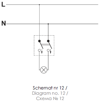
Single pole with a two-way switch (separate power supply)
Single pole with two-way switch
- Karlik Elektrotechnik Sp. z o.o.
- 62-330 Nekla
- tel. +48 61 437 34 00
- e-mail: karlik@karlik.pl
- www.karlik.pl.
Documents / Resources
 |
Karlik Switches Connection Diagrams [pdf] User Manual Switches Connection Diagrams, Switches, Connection Diagrams, Diagrams |


