JBC PHSE IR Preheater Set

Specifications
- PHSE
- Preheater for PCBs up to 13x13cm/5×5”
- Ref.: PHSE-9B 100V. Input 100V 50/60Hz Fuse T10A
- Ref.: PHSE-1B 120V. Input 120V 50/60Hz Fuse T10A
- Ref.: PHSE-2B 230V. Input 230V 50/60Hz Fuse T5A
- Maximum Power: 800W
- Heating Area: 65 x 135 mm / 2.56 x 5.31 in – 1 zone
- 130 x 135 mm / 5.12 x 5.31 in – 2 zones
- Ambient Operating Temperature: 10 – 40 ºC / 50 – 104 ºF
- Temperature Range: 50 – 250 °C / 120 – 482°F
- Temperature Measurement: Thermocouple type K
- Accuracy: ± 5 °C / ± 10 °F
- JBC Set Temperature Profiles: 3 profiles (2, 3 or 4 steps)
- User Profiles: 20 (up to 16 steps for each)
- Maximum Work Time: 600 min or indefinite
- Preheater Dimensions(L x W x H): 195 x 288 x 42 mm / 7.68 x 11.34 x 1.65 in
- Total Net Weight: 2.60 kg / 5.73 lb
- Total Package Dimensions / Weight: 368 x 368 x 125 mm / 3.58 kg
- (L x W x H) 14.45 x 14.45 x 4.92 in / 7.89 lb
- Complies with CE standards
- ESD safe
Product Usage Instructions
Features and Connections:
- Heating Areas with Zone A and Zone B
- Led Status Indicator (Blue for resting, Green for running, Red for stopped, Flashing red for error)
- Thermocouple Connectors x4 (Type K)
- RJ12 Connector to Robot
- RJ45 Connector to Console
- USB-B Connector
- Main Switch Power Socket and Pedal Connector
Status Indicator:
The LED status indicator shows different colours for various states of the preheater – Blue for resting, Green for running, Red for stopped, and flashing red for error.
Main Menu:
The main menu on the console allows you to set parameters, choose operating modes, create profiles, display graphics, manage files, check counters, select language, and reset station parameters.
Work Screen:
The console provides an intuitive user interface with a status bar displaying real-time information like instant power supplied to the heater and thermocouple current temperature.
This manual corresponds to the following references:
- PHSE-9B (100 V)
- PHSE-1B (120 V)
- PHSE-2B (230 V)
Packing List
The following items are included:

Features and Connections
Preheater Unit

Console 
Status Indicator
The LED status indicator indicates the status of the preheater as follows:
Blue:
The unit is resting, not heating. On the display, the symbol ![]() “Stop” (1) is shown.
“Stop” (1) is shown.
Green:
The unit is running and heating accordingly to the operating mode. On the display, the symbol “Play” (2) is shown.
Red:
The unit has stopped after having finished a heating cycle. The red light indicates that the glass of the heating unit may be hot. After cooling down, the LED turns blue and the symbol  “Stop” (1) appears on the display.
Flashing red:
An error has occurred. The console display indicates the error type.
Main Menu


- Set the preheater parameters.
- Choose between Temperature, Power or Profile modes.
- Choose between 3 JBC preset profiles or create up to 25 new profiles.
- Display and save graphics in real time.
- Export/import data (graphics or profiles).
- Check working hours, mode hours, etc.
- Choose the system language: English, Spanish, German, French, Italian, Portuguese, Japanese, Chinese, Russian or Korean.
- Restore station parameters to default values.
Work Screen
The console offers an intuitive user interface, which provides quick access to station parameters.
- Default pin: 0105.

Status Bar and System Notifications
System notifications are displayed on the status bar:
 USB flash drive is connected.
 The device is controlled by a PC.
 The device is controlled by a robot.
 The beep of the buttons is on.
 Device software update.
- Press INFO to start the process.
 Warning. Press INFO for failure description.
 Error. Press INFO for failure description, the type of error and how to proceed.
Troubleshooting
- Station troubleshooting is available on the product page on www.jbctools.com.
Setting Thermocouples Function
- Select Thermocouples from the Work mode menu to set them up.
- The thermocouples (TC) can work in three different ways depending on what is needed.
 Control: the unit maintains the selected temperature.
- Protection: the Heater Unit stops if the TC reaches the selected temperature.
- Info: The temperature is shown on the work display.
- The TC1 is always working in Control mode for the Temperature mode as well as for Profiles mode.
- The temperature of each TC can also be selected from the work display.
Recommended Guidelines
- Place the control thermocouple as near as possible to the component being worked on.
- If there are any sensitive components, use a thermocouple as protection.
- You can select the protection temperature in the thermocouples menu. If the selected temperature is reached, the Heater Unit will stop the process, and a warning message will be shown.

- You can select the protection temperature in the thermocouples menu. If the selected temperature is reached, the Heater Unit will stop the process, and a warning message will be shown.
- We don’t recommend exceeding ramp-up rates over 3 – 4 °C / sec (5 – 7 °F / sectoto reduce the risk of thermal stress on the PCB.
Work Mode
 Temperature Mode:
Select Temp. Mode from the Work mode menu. In this mode, the heater unit maintains the selected temperature for the TC1 thermocouple as long as the other TCs do not reach the control/protection temperature limit.
 Working within the Temperature Mode, the maximum heating rate value (Max Rate) can be defined (1).

- This function allows you to set a maximum value for the temperature increase per second when heating.
- The maximum heating rate value can be set between 0.10C/s and 2.00C/s (2) or “None” if this function is not desired.

Power Mode:
Select Power mode from the Work mode menu. In this mode, the heater unit maintains the selected power as long as the thermocouples do not reach the control/protection temperature limit.

Profile Mode:
Select Profile mode from the Work mode menu. In this mod, the heater unit regulates the temperature of the TC1 thermocouple according to the selected profile as long as the other TCs do not reach the control/protection temperature limit.

Teach Profile
- For repetitive jobs, it is also possible to run customised profiles without the thermocouple (TC). To do so, the Teach profile option has to be executed before running any profile. It can be executed from the Work mode menu if the Profile mode is selected. The first time, the thermocouple must be connected. Once the profile has been run to the end, the system has all the process data to be saved.
- Once it is saved, you can run this profile without connecting the thermocouple (TC). The heating process will be the same as long as the same working conditions are respected.
- The profiles which already have the data from the Teach profile are marked with this symbol

- These profiles can be run either with or without thermocouples. This can be selected from the
Profile mode work screen:

Profile Editor

- The Profile editor can be opened from the main menu or the Profiles mode work screen by pressing the ‘OK’ button.
- In this mode, the user can choose between the 3 JBC-preset profiles or create and save up to 22 new profiles.

JBC Predefined Profiles
- There are 3 profiles predefined by JBC: A, B and C. The difference between them is the number of steps: 2, 3 or 4. The thicker your PCB is and the more layers it contains, the more steps are needed o obtain gradual warming.
- Predefined profiles use the low position of the support.
- These profiles are not modifiable b, but they can be used as templates to create your profiles.

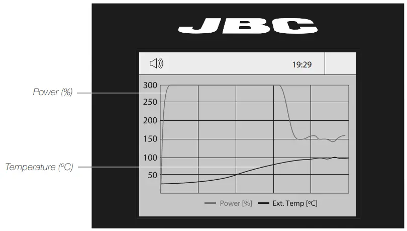
Graphics
 By pressing Graphics on the main MENU, the temperature of the TC1 and the power are displayed in real time.
Graphics Display/Save
- Select the desired work mode (Temp., Profiles or Power).
- Press the menu button (
 ) and select Graphics.
 - A pop-up window appears asking, “Do you want to save data?”.

- a A pop-up message appears: “Saving data”.
This process takes several minutes. - a The console displays the graphics screen.
- a Press the start button to start working. The graphics are displayed in real time until leaving the graphics screen.

- 4.b The graphics screen is displayed immediately.
- 5.b Press the start button to start working. The graphics are displayed in real time until leaving the graphics screen.
Files
 Exporting Graphics Data and Exporting/Importing Profile Data
Note: To export graphics/profiles, it is required to first save at least one data file (see Profile Editor/Graphics sections).

- Connect a USB pen drive to the console. To export files, it is recommended that the pen drive be empty.
- On the main menu, select Files, and then Graphics or Profiles.
- Various options are displayed:
- To delete a file, select Remove.
- To export a saved file, select Export. A confirmation pop-up window appears, and then the data is exported to the pen drive.
- To import a profile (Profiles only) from the pen drive, select Import.
Updating the Station Software
- Download the JBC Update File from www.jbctools.com/software.html and save t on a USB flash drive (preferably one with no other files).

- Insert the USB pen drive into the console. The icon
 is displayed while updating.
Working with Pedal
- Press the pedal to start heating and press again to stop, as if it were the button on the console.
- Once the work mode is defined, the heater unit can work without the console by using the pedal.

Maintenance
- Before carrying out maintenance or storage, always allow the equipment to cool down.
- Check periodically that the equipment is clean.
- Use a damp cloth when cleaning. Alcohol can only be used to clean the metal parts.
- Only if it is necessary and if cleaning with isopropyl alcohol (IPA) is not enough, it is recommended to use a scraper to remove dirt in the glass area.
- Replace any defective or damaged parts. Use original JBC spare parts only.
- Repairs should only be performed by a JBC-authorised technical service.
- A blown fuse can be replaced by the user.
- The fuse is located between the power supply connector and the on/off switch (1). To replace a blown fuse, proceed as described below.
- Important: Make sure that the preheater is disconnected from the power supply.


Reference for Replacement Fuse:
- PHSE-9B (100V), fuse T10A Ref. 0032666
- PHSE-1B (120V), fuse T10A Ref. 0032666
- PHSE-2B (230V), fuse T5A Ref. 0032687
Safety
![]() It is imperative to follow safety guidelines to prevent electric shock
It is imperative to follow safety guidelines to prevent electric shock
- Do not use the units for any purpose other than PCB preheating. Incorrect use may cause a fire.
- The mains cable must be plugged into approved bases. Make sure that it is properly grounded before use. When unplugging it, hold the plug, not the wire.
- The temperature of accessible surfaces may remain high after the unit is turned off. Handle with care.
- Do not leave the appliance unattended when it is on.
- Do not cover the ventilation grills. Heat can cause inflammable products to ignite.
- Heat can cause inflammable products to ignite even when out of sight.
- Be careful with the remains of liquid tin. In contact with the skin, it can cause burns.
- Avoid flux coming into contact with skin or eyes to prevent irritation.
- Be careful with the smoke produced when soldering.
- Keep your workplace clean and tidy. Wear appropriate protective glasses and gloves when working to avoid personal harm.
- This appliance can be used by children over the age of eight as well as persons with reduced physical, sensory or mental capabilities or lacking experience, provided that they have been given adequate supervision or instruction concerning the use of the appliance and understand the hazards involved.
- Children must not play with the appliance.
- Maintenance must not be carried out by children unless supervised.
Warranty
- JBC’s2-yearr warranty covers this equipment against all manufacturing defects, including the replacement of defective parts and labour.
- Warranty does not cover product wear or misuse. For the warranty to be valid, the equipment must be returned, postage paid, to the dealer where it was purchased.
- Get 1 extra year of JBC warranty by registering here: https://www.jbctools.com/productregistration/ within 30 days of purchase.
- If you register, you will receive e-mail notifications about new software updates for your registered product.
 This product should not be thrown in the garbage. By the European directive 2012/19/EU, electronic equipment at the end of its life must be collected and returned to an authorised recycling facility
FAQs
Q: What do the different LED colors on the preheater unit indicate?
A: Blue indicates resting state, Green indicates running and heating, Red indicates stopped after a cycle (may be hot), and Flashing red indicates an error.
Q: How many preset profiles can be chosen on the console?
A: The console offers 3 preset profiles and the option to create up to 25 new profiles.
Documents / Resources
 |
JBC PHSE IR Preheater Set [pdf] Instruction Manual PHSE-9B 100 V, PHSE-1B 120 V, PHSE-2B 230 V, PHSE IR Preheater Set, PHSE, IR Preheater Set, Preheater Set, Set |