JBC DME-9A 4-Tool Control Unit Instruction Manual
www.jbctools.com/dme-product-925.html
www.jcbtools.com
This manual corresponds to the following references:
DME-9A (100V)
DME-1A (120V)
DME-2A (230V)
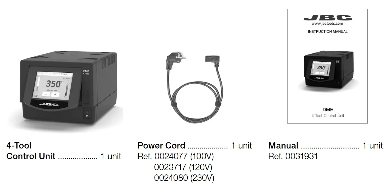
Packing List
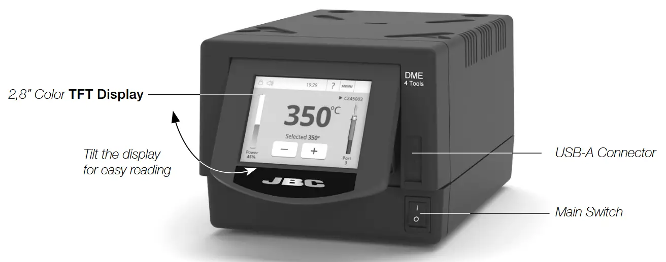
Features
DME works simultaneously with up to 4 tools, 1 module and 1 pedal for each tool (peripheral module for each tool needed).
Connection Example
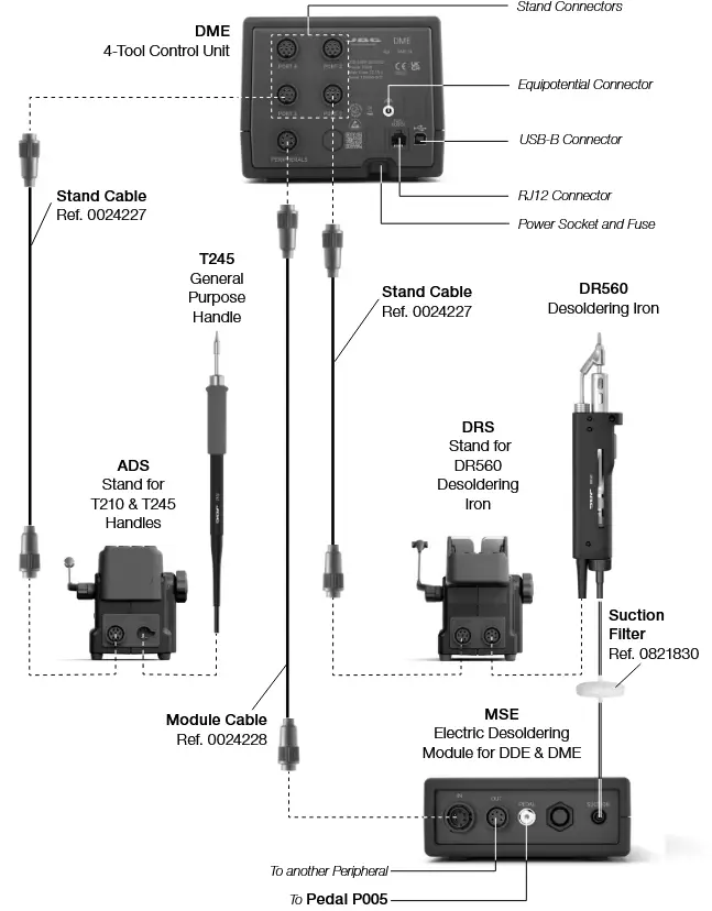
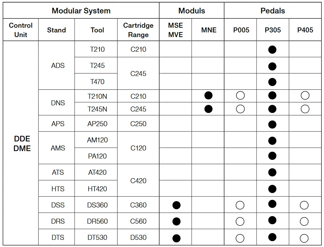
Compatibility
Combine the equipment that best suit your soldering or desoldering needs.
Marked with ◯ means pedals P405 and P005 cannot be connected directly to JBCs control units DDE and DME. A module must be used and the pedals are connected to the module.
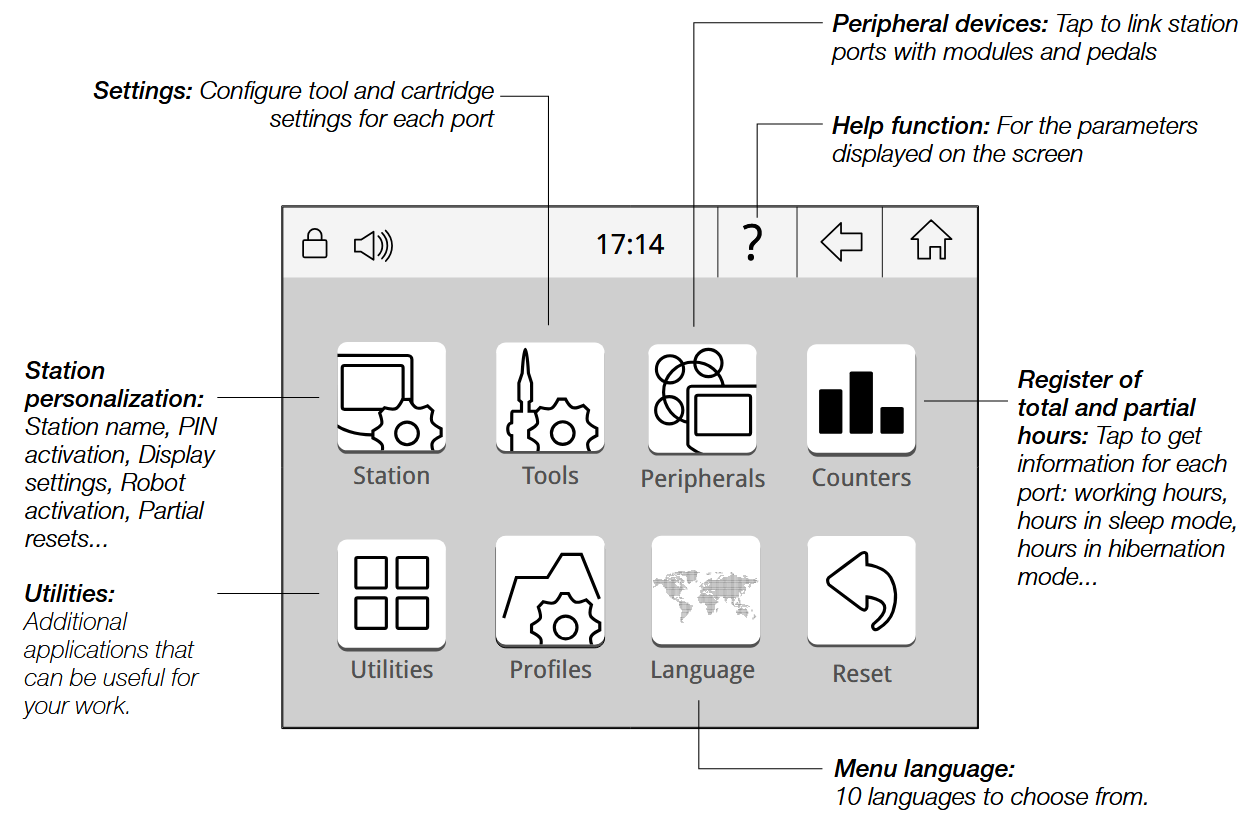
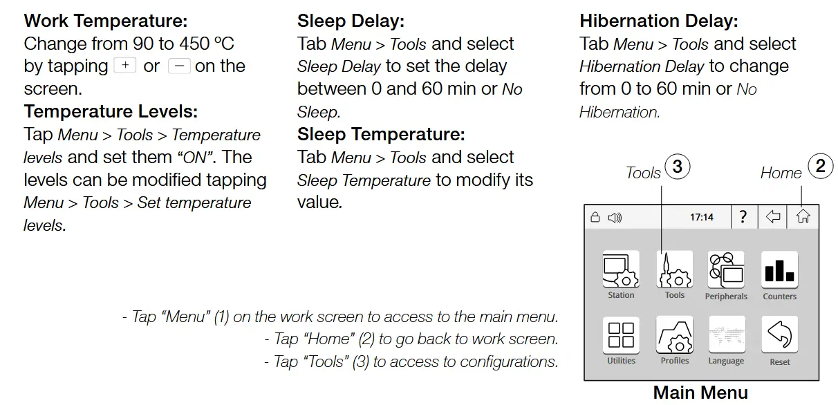
Work Screen
DME offers an intuitive user interface which provides quick access to the station parameters.
Default PIN: 0105

Troubleshooting
Station troubleshooting available on JBC’s web page:
www.jbctools.com/troubleshooting-soldering-station.html
It provides detailed graphics of tip temperature and power delivery in real-time during solder joint formation for analysis purposes. This helps you decide how to adjust your process or which tip to use to obtain the best quality soldering.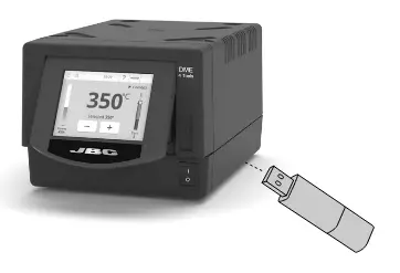

Export graphics
Insert a USB flash drive into the USB-A connector to save your soldering process in CSV format.

Play videos
Enables to play video files from a USB device as long as it is in AVI format and 320x240px.

Provides the possibility to connect a microscope* by USB connection to the station. The image will be shown on the station display.
* compatible with: Dino Lite AM2111 and AM2011

Provides calculator environment and function.

Enables to convert, for example, ºC values into ºF values.
System notifications
The following icons will be displayed on the screen status bar.
![]() USB flash drive is connected.
USB flash drive is connected.
![]() Station is controlled by a PC.
Station is controlled by a PC.
![]() Station is controlled by a robot. downloaded to the station.
Station is controlled by a robot. downloaded to the station.
![]() Station software update. Press INFO to start the process.
Station software update. Press INFO to start the process.
![]() Warning. Press INFO for failure description.
Warning. Press INFO for failure description.
![]() Error. Press INFO for failure description, the type of error and how to proceed.
Error. Press INFO for failure description, the type of error and how to proceed.
MSE / Pedal Initial Setup
![]() After connecting the electric desoldering module (MSE-A), a popup window is opened.
After connecting the electric desoldering module (MSE-A), a popup window is opened.
Peripherals
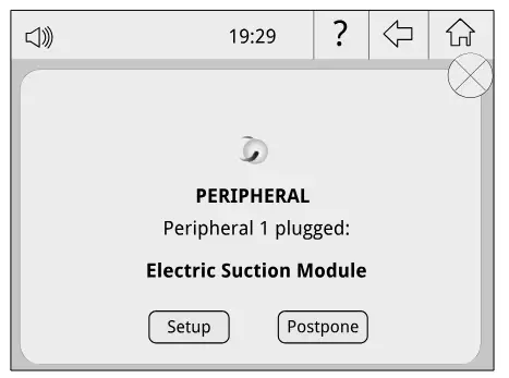
1. To configure your Electric Suction Module press Setup in the popup window.
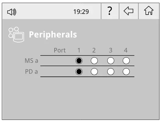
2. Select the module from the list of peripheral connections. Remember your first connection is denoted as “a”, the second being “b”, etc. (e.g. MS_a, MS_b,…). Do the same with the pedal (e.g. PD_a,…)
3. Select the port of the tool you want to link to the peripheral.
4. Press Menu ![]() or Back
or Back ![]() to save changes. Once set up, the module settings can be changed by entering the Peripherals Menu.
to save changes. Once set up, the module settings can be changed by entering the Peripherals Menu.
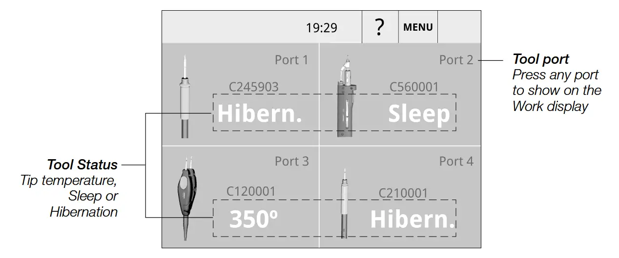
Simultaneous Ports Control
See the information for all ports in real time when pressing the tool image on the Work display.
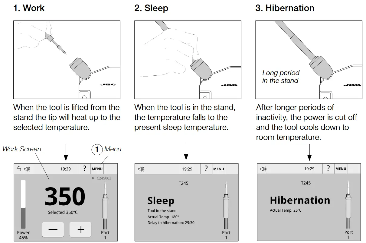
Operation
Our revolutionary technology is able to recover tip temperature extremely quickly. It means the user can work at a lower temperature and improve the soldering quality. The tip temperature is further reduced thanks to the Sleep and Hibernation modes which increase up to 5 times the life of the tip.
JBC’s Most Efficient Soldering System
USB Connector and Firmware Update
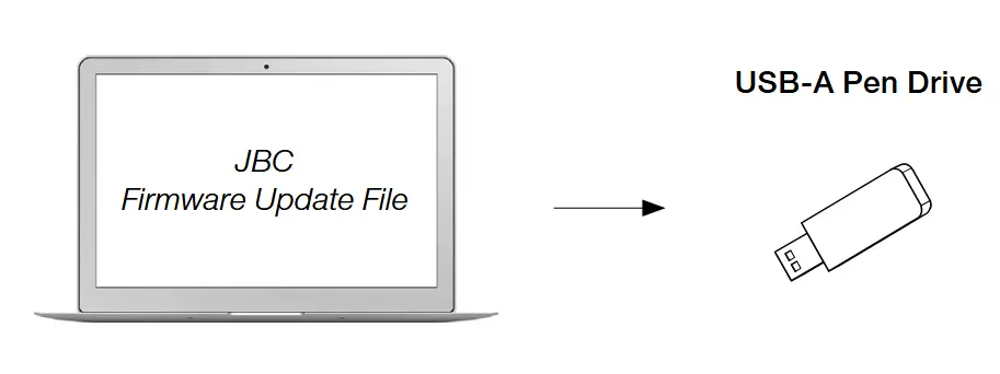
Download: JBC Firmware Update File
Download the JBC firmware update file from www.jbctools.com/software.html, which contains the latest update package. Extract the .jpu file to the root folder of a USB-A pen drive (FAT32), preferably with no other files.
Connection: USB-A Pen Drive to Control Unit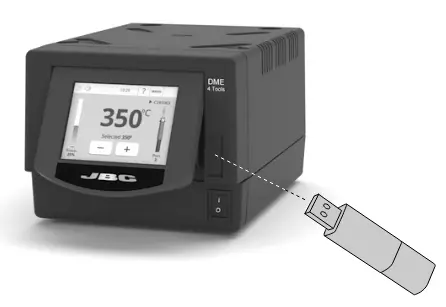
Connect the USB-A pen drive which contains the latest update file and the update notification to the control unit.
This symbol ![]() will be displayed automatically.
will be displayed automatically.
If the DME control unit does not detect the USB pen drive, please use a pen drive partitioning software.
Installation: JBC Firmware Update File
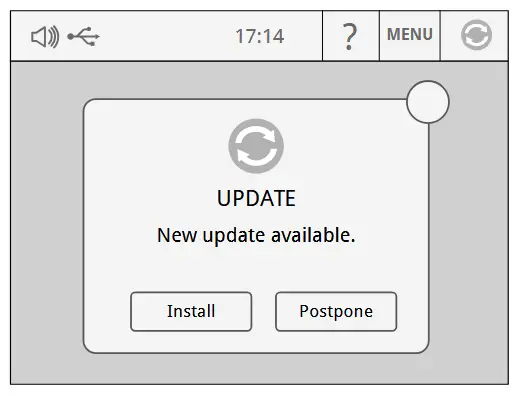
Press “Install” on the pop-up window. If ![]() is not displayed, tap on the notification.
is not displayed, tap on the notification.
Updating Process
During the updating process do not turn off the control unit, it may turn on and off automatically. The installation finishes when the updating bar is completed and the work screen is displayed.
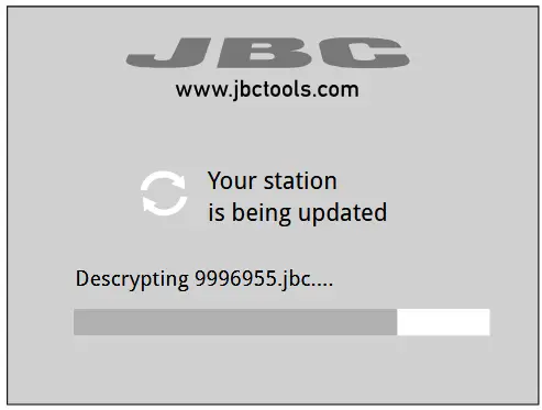
The work screen will be displayed after confirming the “Welcome” pop-up.
If the process stops for a long time (over 30 min), reset the station and wait until the installation is fully completed.
Checking Firmware Version
Check that the new firmware has been installed successfully by means of the following steps:
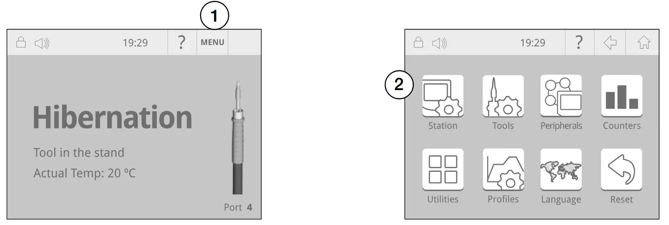
First select “Menu” (1) and then the “Station” icon (2) on the screen.
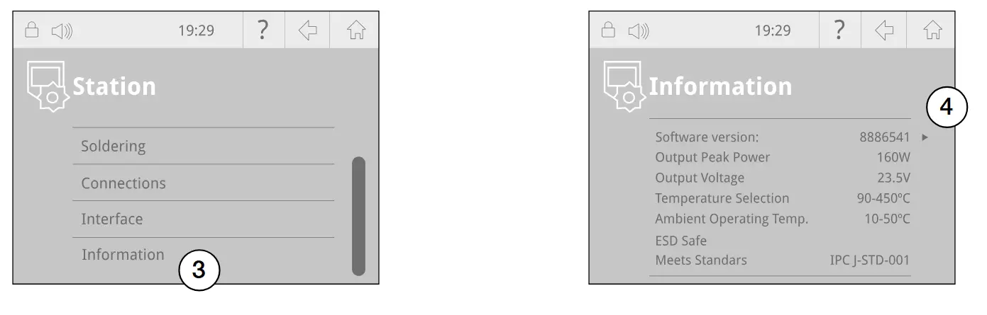
Select “Information” (3) and then press ▶ (4) to check the firmware version.
Maintenance

Before carrying out maintenance or storage, always allow the equipment to cool.
– Clean the station display with a glass cleaner or a damp cloth.
– Use a damp cloth to clean the casing and the tool. Alcohol can only be used to clean the metal parts.
– Periodically check that the metal parts of the tool and stand are clean so that the station can detect the tool and establish its status.
– Maintain tip surface clean and tinned prior to storage in order to avoid tip oxidation. Rusty and dirty surfaces reduce heat transfer to the solder joint.
– Periodically check all cables and tubes.
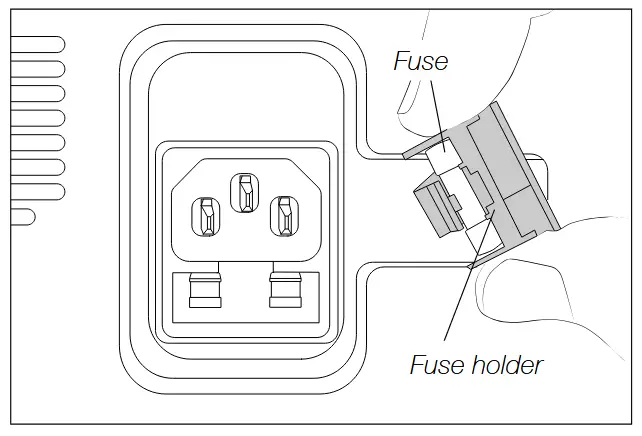
– Replace a blown fuse as follows:
- Pull off the fuse holder and remove the fuse. If necessary use a tool to lever it off.

- Insert the new fuse into the holder and return it to the station.
– Replace any defective or damaged pieces. Use original JBC spare parts only.
– Repairs should only be performed by a JBC authorized technical service.
Safety
![]() It is imperative to follow safety guidelines to prevent electric shock, injury, fire or explosion.
It is imperative to follow safety guidelines to prevent electric shock, injury, fire or explosion.
– Do not use the units for any purpose other than soldering or rework. Incorrect use may cause a fire.
– The power cord must be plugged into approved bases. Be sure that it is properly grounded before use. When unplugging it, hold the plug, not the wire.
– Do not work on electrically live parts.
– The tool should be placed in the stand when not in use in order to activate the sleep mode. The soldering tip or nozzle, the metal part of the tool and the stand may still be hot even when the station is turned off. Handle with care, including when adjusting the stand position.
– Do not leave the appliance unattended when it is on.
– Do not cover the ventilation grills. Heat can cause inflammable products to ignite.
– Avoid flux coming into contact with skin or eyes to prevent irritation.
– Be careful with the fumes produced when soldering.
– Keep your workplace clean and tidy. Wear appropriate protection glasses and gloves when working to avoid personal harm.
– Utmost care must be taken with liquid tin waste which can cause burns.
– This appliance can be used by children over the age of eight and also people with reduced physical, sensory or mental capabilities or lack of experience provided that they have been given adequate supervision or instruction concerning the use of the appliance and understand the hazards involved. Children must not play with the appliance.
– Maintenance must not be carried out by children unless supervised.
Specifications
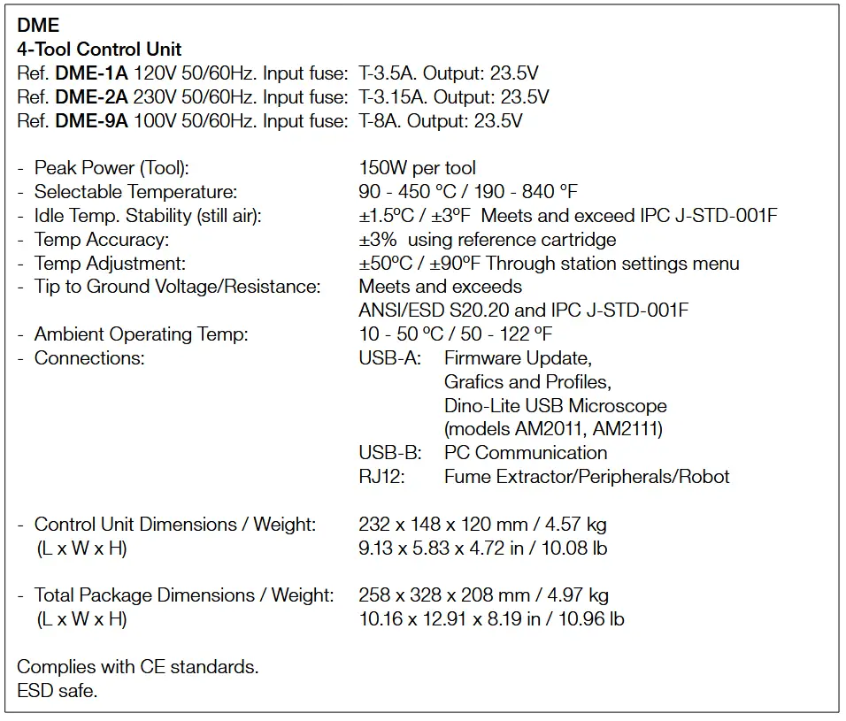
![]()
Warranty
JBC’s 2 year warranty covers this equipment against all manufacturing defects, including the replacement of defective parts and labor.
Warranty does not cover product wear or misuse. In order for the warranty to be valid, equipment must be returned, postage paid, to the dealer where it was purchased.
Get 1 extra year JBC warranty by registering here: https://www.jbctools.com/productregistration/ within 30 days of purchase.
If you register, you will receive e-mail notifications about new software updates for your registered product.
![]() This product should not be thrown in the garbage.
This product should not be thrown in the garbage.
In accordance with the European directive 2012/19/EU, electronic equipment at the end of its life must be collected and returned to an authorized recycling facility.
![]()
Documents / Resources
 |
JBC DME-9A 4-Tool Control Unit [pdf] Instruction Manual DME-9A, DME-9A 4-Tool Control Unit, 4-Tool Control Unit, Control Unit |