 JBC ALE Series Automatic Feed Soldering Control Unit

Specifications
- Product Name: ALE Automatic-Feed Soldering Control Unit
- Voltage Options: 100V, 120V, 230V
- Models with Solder Wire Perforation: ALE-908UVA, ALE-108UVA, ALE-208UVA, and more
- Models Without Solder Wire Perforation: ALE-904UA, ALE-104UA, ALE-204UA, and more
- Power Cord: Included (120V or 230V)
Packing List
Ensure the following items are included:
- Automatic-Feed Soldering Control Unit – 1 unit
- Power Cord – 1 unit (Ref. 0023717 for 120V, 0024080 for 230V)
- Manual – 1 unit (Ref. 0030217)
- Key Set for SF / AL – 1 unit (Ref. 0019341)
Assembly and Components
- Make sure components are correctly assembled in the Control
- Unit. Use the provided Solder Wire Guide Kit for proper setup.
Features and Connections
The product includes features like Solder Reel Stand, Display, USB connectors, Main Switch, and more. Ensure proper connections for effective operation.
Cartridge Assembly
Follow these steps for safe cartridge assembly/change:
- Ensure the tool is unplugged and cooled down.
- Loosen the cartridge set screw, remove the used cartridge, and insert the new cartridge up to its mark.
- Adjust the cartridge tip direction and tighten the cartridge set screw.
This manual corresponds to the following references:

Note: For correct operation, the diameter of the solder wire in use must match the diameter of the ALE reference purchased.
Packing List

Packing List

- Note: For correct operation, the diameter of the solder wire in use must match the diameter of the purchased guide kit.
- Guide sets for different diameters are available at: www.jbctools.com/solder-wire-guide-kit-product-2098.html
Features and Connections

Cartridge Assembly
- For a safe cartridge assembly/change, make sure that the tool is unplugged and that any cartridge in place has cooled down before following these guidelines:
- Loosen the cartridge set screw (1), remove the used cartridge if there is any already in place, and insert the new cartridge up to its mark (2).
- Important: It is essential to insert the cartridge completely for a good connection. Use the mark as reference (3).
- Adjust the cartridge tip direction (4) and tighten the cartridge set screw (1).

Guide Tube Set Assembly
- Open the guide tube set screw (1) and insert the guide tube set.
- Adjust the guide tube length (2). Leave a gap of 5 to 7 mm (0.19 to 0.27 in) between the tip and the outlet nozzle (3). Once the position is adjusted tighten the guide tube set screw (1).
- For better handling, use the clips (4) to attach the guide tube to the tool cable.

Outlet Nozzle Replacement
Flux can cause clogging at the outlet nozzle of the guide tube set, and it may be necessary to replace the worn or clogged outlet nozzle. Note: There is a nozzle size for each soldering wire diameter. The use of the nozzle is necessary as its inner diameter is adjusted to the solder wire diameter and guides the wire with greater precision. To replace the outlet nozzle, follow these steps: First, make sure that the tool has cooled down and unload any remaining solder wire that might still be inside the guide tube (see pages 11 and 12). Unplug the tool. Loosen the guide tube set screw (1) and detach the guide tube set from the tool for easier handling.

Tool Assembly
- Connect the tool to the control unit following these steps:
- Loosen the set screw, insert and push the guide nozzle until it stops (1) and tighten the set screw (2) again. Then plug in the tool connector (3).

Solder Reel Assembly

Loosen the reel locking screw (1) and remove the reel locking (2) from the axis. Assemble the solder reel onto the axis (3).
Assemble the solder reel in such a way – when viewed from above – that the solder wire unwinds on the dispensing mechanism side (4). Then pass the solder wire through the wire guidance (5).

Reel Locking Assembly

Align the flat side of the axis (2) with the inner flat side (the one with the screw) of the reel locking (3) and reassemble it to the axis (4).
Note: To prevent the solder reel from spinning freely or binding, before tightening the reel locking screw gently press the reel locking down, but only enough to allow the solder reel to rotate freely, before tightening the reel locking screw (5).
Main Menu Screen
Acces to Main Menu by pressing ![]() , select “Feeder settings” (1) and then “Wire diameter” (2) to adjust the value to the current solder wire diameter.
, select “Feeder settings” (1) and then “Wire diameter” (2) to adjust the value to the current solder wire diameter.

Solder Wire Loading
Pass the solder wire through the wire guidance and introduce the solder wire into the inlet nozzle
- until it reaches the wheels
- Select “Tinreload process” and then use
 to feed the solder wire and advance until it comes out of the outlet nozzle.
If needed, carefully push the wire until it gets locked in between the rotating wheels for the wire to start moving forward. Keep pressed and after a while, the wire will advance faster.
Make sure the wire passes through the intermediate nozzle (3) and enters the guide tube (4).

Solder Wire Feeding
Forward the solder wire by pressing the dragging button (1) until the wire comes out of the tip (2).

Alternatively, solder wire can also be fed using the pedal P405. The pedal should be plugged in at the rear of the feeder control unit into the pedal connector.

Solder Wire Unloading
With Solder Wire Perforation, to unload solder wire with perforation that has already passed through the guide tube, cut the wire between the wire guidance and the inlet nozzle (1
To extract the wire out of the tube, hold the tool in your hand and press![]() forward. Until the wire stops
forward. Until the wire stops
Grasp the wire coming out of the outlet nozzle with a pliers and pull until it is completely out.

Solder Wire Unloading
Without Solder Wire Perforation
When using a kit without solder wire perforation, press ![]() until the wire is completely wound to unload the solder wire. It is best to rotate the reel by hand as the wire is being pulled back in order to keep it neatly arranged on the reel. Or, If preferred, proceed as described before for perforated solder wire unloading.
until the wire is completely wound to unload the solder wire. It is best to rotate the reel by hand as the wire is being pulled back in order to keep it neatly arranged on the reel. Or, If preferred, proceed as described before for perforated solder wire unloading.

Guide Kits Disassembly
- For this operation, disconnect the device from the mains. Unload any solder wire running inside the guide tube, disconnect the tool from the control unit and open its cover.
- Before trying to remove any components, be sure to loosen the corresponding set screws. To do this, use the Allen key and spanner provided with the station.
- First, disassemble the guide tube set (1), the guide wheel (4), the blade and blade clamp (5), and then the nozzles (2) + (3). Note: The wheel components® on devices without solder wire perforation (10) are slightly different from those with solder wire perforation.
- Lastly, disassemble the counter wheel (6), introducing the Allen key through the frontal opening (9) to loosen its set screw.

Guide Kits Assembly – with Solder Wire Perforation:
Assemble first the counter wheel (1). Make sure that its thread entry for the set screw is aligned with the flat side of the axis (2). If not, the set screw will protrude, which may cause difficulties for the wire transportation.
Inserting the Allen key through the front opening will make it easier to tighten the screw (3).
Afterwards Insert the intermediate nozzle (4) until its collar rests against the housing and tighten its screw.


Guide Kits Assembly – without Solder Wire Perforation:
- Assemble first the counter wheel (1) in the same way as shown on the previous page (see (1), (2), and (3) on the page before).
- Afterwardas insert the intermediate nozzle (2) until its collar rests against the housing and tighten its screw.
- Assemble the inlet nozzle (3).
- Assemble the support wheel* (4) and the traction wheel (5) on the corresponding axis and tighten the respective scre.ws
- Finally insert the guide tube set (6) and tighten the screw.

Control Process
Feeder Setting Modes
Access to Main Menu by pressing , ![]() select “Feeder Settings” and then “Mode”. Choose between “continuous”, “discontinuous” and “program” mode.
select “Feeder Settings” and then “Mode”. Choose between “continuous”, “discontinuous” and “program” mode.

Troubleshooting
- Station troubleshooting ng available on the product page at www.jbctools.com
Program Mode
With ALE C.U. there can be up to 5 feeder programs defined. Select “Edit Program” and access the program parameters.

- For each program, between 1 and 3 feeding steps (length and speed) should be defined.
- If fewer than 3 feeding steps are needed, set up wire length and speed to “0.0” and the parameter will change to “None”.
- Quick Access to Feeder Setting Modes
- The solder wire dispensing values can be directly set up from the work screen.
- Press
 or to change the tool temperature value.
When the main screen is displayed, speed and length values can be set up by pressing ok. The following parameters can be changed according to the different dispensing modes:- Continuous Mode: Speed
- Discontinuous Mode: Speed and length
- Program Mode: 3 feeding parameter pairs (length and speed) for every program.
Note: First, select the program to be modified at the work screen by selecting the program. >AND< to switch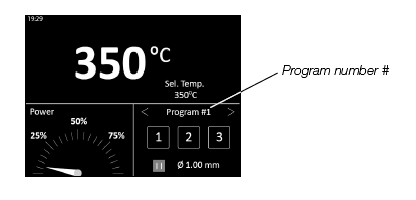
Control Process

Maintenance
Before carrying out maintenance, always switch the device off and disconnect it from the mains. Allow the equipment to cool down.
- Clean the station display with a glass cleaner or a damp cloth.
- Use a damp cloth to clean the casing and the tool. Alcohol can only be used to clean the metal parts.
- Periodically check that the metal parts of the tool and stand are clean so that the station can detect the tool’s status.
- Maintain the tip surface clean and tinned prior to storage in order to avoid tip oxidation. Rusty and dirty surfaces reduce heat transfer to the solder joint.
- Periodically check all cables and tubes.
- Replace any defective or damaged pieces. Use only original JBC spare parts.
- Repairs should only be performed by a JBC authorized technical service.

EARTH
- FUSE When this warning appears on the main screen, the earthing fuse must be replaced.
- Replace a blown fuse as follows (applies to both the earthing fuse and the main fuse):
- Pull off the fuse holder and remove the fuse.
If necessary, use a tool to lever it off. - Insert the new fuse into the fuse holder and return it to the station.
- Pull off the fuse holder and remove the fuse.


Safety
It is imperative to follow safety guidelines to prevent electric shock, injury, fire, or explosion.
- Do not use the units for any purpose other than soldering or rework. Incorrect use may cause a fire.
- The power cord must be plugged into approved bases. Be sure that it is properly grounded before use. When unplugging it, hold the plug, not the wire.
- Do not work on electrically live parts.
- The tool should be placed in the stand when not in use in order to activate the sleep mode. The soldering tip or nozzle, the metal part of the tool, and the stand may still be hot even when the station is turned off. Handle with care, including when adjusting the stand position.
- Do not leave the appliance unattended when it is on.
- Do not cover the ventilation grills. Heat can cause inflammable products to ignite.
- Avoid flux coming into contact with skin or eyes to prevent irritation.
- Be careful with the fumes produced when soldering.
- Keep your workplace clean and tidy. Wear appropriate protective eyeglasses and gloves when working to avoid personal harm.
- Utmost care must be taken with liquid tin waste, which can cause burns.
- This appliance can be used by children over the age of eight and also people with reduced physical, sensory or mental capabilities or lack of experience provided that they have been given adequate supervision or instruction concerning the use of the appliance and understand the hazards involved. Children must not play with the appliance.
- Maintenance must not be carried out by children unless supervised.
Specifications


Warranty
- JBC’s 2-year warranty covers this equipment against all manufacturing defects, including the replacement of defective parts and labor.
- Warranty does not cover product wear or misuse.
- In order for the warranty to be valid, equipment must be returned, postage paid, to the dealer where it was purchased.
- Get 1 extra year of JBC warranty by registering here: https://www.jbctools.com/productregistration/ within 30 days of purchase.
- If you register, you will receive email notifications about new software updates for your registered product.
This product should not be thrown in the garbage.
By the European directive 2012/19/EU, electronic equipment at the end of its life must be collected and returned to an authorized recycling facility.
FAQS
Q: Do I need to match the solder wire diameter with the purchased reference?
A: Yes, for correct operation, ensure the solder wire diameter matches the purchased reference or guide kit.
Q: Are additional guide kits available for different solder wire diameters?
A: Yes, guide sets for different diameters are available at www.jbctools.com/solder-wire-guide-kit-product-2098.html.
Documents / Resources
 |
JBC ALE Series Automatic Feed Soldering Control Unit [pdf] Instruction Manual ALE-908UVA, ALE-108UVA, ALE-208UVA, ALE-915UVA, ALE-115UVA, ALE-215UVA, ALE-910UVA, ALE-110UVA, ALE-210UVA, ALE-916UVA, ALE-116UVA, ALE-216UVA, ALE Series Automatic Feed Soldering Control Unit, ALE Series, Automatic Feed Soldering Control Unit, Soldering Control Unit, Control Unit |
 |
JBC ALE Series Automatic Feed Soldering Control Unit [pdf] Instruction Manual ALE-908UVB, ALE-108UVB, ALE-208UVB, ALE-915UVB, ALE-115UVB, ALE-215UVB, ALE-910UVB, ALE-110UVB, ALE-210UVB, ALE-916UVB, ALE-116UVB, ALE-216UVB, ALE Series Automatic Feed Soldering Control Unit, ALE Series, Automatic Feed Soldering Control Unit, Feed Soldering Control Unit, Soldering Control Unit, Control Unit |