1. はじめに
This manual provides essential information for the safe and efficient operation of your DATOUBOSS 48V 300Ah LiFePO4 Powerwall Lithium Battery. Please read this manual thoroughly before installation and use, and retain it for future reference. This battery is designed for deep cycle energy storage in various applications including home backup, solar power systems, RVs, and off-grid setups.

Figure 1: DATOUBOSS 48V 300Ah LiFePO4 Powerwall Lithium Battery.
2. 安全情報
警告: これらの安全指示に従わなかった場合、感電、火災、重傷、または死亡につながる可能性があります。
- バッテリーを取り扱う際は、必ず絶縁手袋や目の保護具などの適切な個人用保護具 (PPE) を着用してください。
- バッテリー端子をショートさせないでください。
- Do not expose the battery to fire, high temperatures, or direct sunlight.
- バッテリーを水やその他の液体に浸さないでください。
- 設置および操作中は適切な換気を確保してください。
- バッテリーを子供やペットの手の届かない場所に保管してください。
- Only use compatible chargers and inverters.
- バッテリーを開けたり、分解したり、修理したりしないでください。修理が必要な場合は、資格のある担当者にご連絡ください。
- 地域の規制に従ってバッテリーを廃棄してください。
- Ensure the installation environment is free from flammable materials.

図2:以上view of the battery's multiple protection functions, including overvoltage, overcharge, overdischarge, short circuit, and temperature protections.
3.製品オーバーview
3.1 主な特徴
- High-Quality LiFePO4 Cells: Utilizes A-grade LiFePO4 cells for durability and long cycle life (up to 15,000 cycles).
- Advanced 210A BMS: Integrated Battery Management System provides comprehensive protection against various electrical faults.
- スマートLCDディスプレイ: リアルタイムのボリューム監視tage, State of Charge (SOC), temperature, and BMS status.
- 通信インターフェース: Equipped with RS485, CAN, and RS232 for wide inverter compatibility and remote monitoring.
- Scalable Energy Storage: Supports parallel connection of multiple units for increased capacity.
- 柔軟な設置: Designed for both floor-standing and wall-mounted configurations.
- モビリティデザイン: Optional wheels/pulleys for easy relocation.
3.2 パッケージ内容
パッケージにすべてのアイテムが揃っていることを確認します。

Figure 3: Contents of the product package, including the battery pack, mounting bracket, wall-mount brackets, battery connection cables, communication cable, screws, and instruction manual.
- Finished home energy storage battery pack (1 unit)
- 取付ブラケット(1個)
- Wall-Mount Brackets (2 units)
- Positive Battery Connection Cable (1 unit)
- Negative Battery Connection Cable (1 unit)
- Communication cable (1 unit)
- Screws (Set)
- Instruction manual (1 unit)
3.3 コンポーネントの識別

図4:詳細 view of the battery's control panel and ports, including DIP switches, RS485, CAN, RS232 communication ports, reset switch, indicators, battery terminals, push button switch, and air switch.
- DIP アドレス: Switches for parallel communication address selection.
- RS485 (External Communication): Port for external communication.
- RS232: Reserve communication port.
- できる: External communication port.
- リセットスイッチ: Reboots or shuts down the unit when pressed.
- スイッチングインジケーター: Shows switch status.
- 操作インジケータ: 動作ステータスを表示します。
- アラームインジケータ: Alerts for system issues.
- バッテリーインジケーター: Shows remaining capacity.
- バッテリープラス端子: Positive connection point.
- バッテリーマイナス端子: Negative connection point.
- 押しボタンスイッチ: Controls power on/off.
- エアスイッチ: Disconnects input and output.
- 液晶: Touchscreen display for monitoring and control.
4. セットアップとインストール
4.1 インストール場所の選択
- バッテリー パックを可燃性の建築材料の上に設置しないでください。
- It should be installed on a solid surface.
- It is recommended to install the battery box at eye level for easy LCD display readability.
- 最適な動作のためには、周囲温度は 0°C ~ 55°C の範囲にする必要があります。
- It is recommended to install vertically on the wall.
- Ensure sufficient heat dissipation space and wiring removal space (at least 20cm/7.8in from sides, 50cm/19.6in from top/bottom).

Figure 5: Illustration of recommended clearances for wall-mounted installation, showing minimum distances from surrounding surfaces for proper ventilation and access.
4.2 Installation Steps (Wall Mount)
- First, fix the mounting bracket to the wall using expansion screws.
- Fix the wall-mount brackets to the back shell of the machine with short screws.
- Hang the battery unit onto the fixed wall bracket.
Note: Only suitable for installation on concrete or other non-flammable surfaces.
4.3電気接続
Connect the positive and negative battery cables to your inverter or load according to the inverter's manual. Ensure all connections are secure and correctly polarized.
WARNING: Incorrect wiring can cause severe damage to the battery and connected equipment, and poses a fire hazard.
4.4 並列接続(オプション)
Multiple units can be connected in parallel to increase total energy storage capacity. Up to 15 units can be connected in parallel.

Figure 6: Visual representation of how multiple DATOUBOSS battery units can be connected in parallel to expand energy storage capacity.
When connecting battery packs in parallel, use the DIP addressing function. If DIP6 is connected to ON, use the default automatic address assignment. Otherwise, use the DIP switch on the BMS to set the address to distinguish different data packets.

Figure 7: Explanation of DIP switch settings for addressing multiple battery units in a parallel configuration, including binary address assignments.

Figure 8: Diagram illustrating parallel wiring instructions and examples of automatic address assignment for multiple battery units.
5. 操作
5.1 電源のオン/オフ
To power on the battery, ensure the air switch is in the "ON" position, then press the push button switch. To power off, reverse the process.
5.2 LCDディスプレイとモニタリング
The high-definition color LCD screen provides real-time information about the battery's status. You can switch between multiple pages for detailed data.
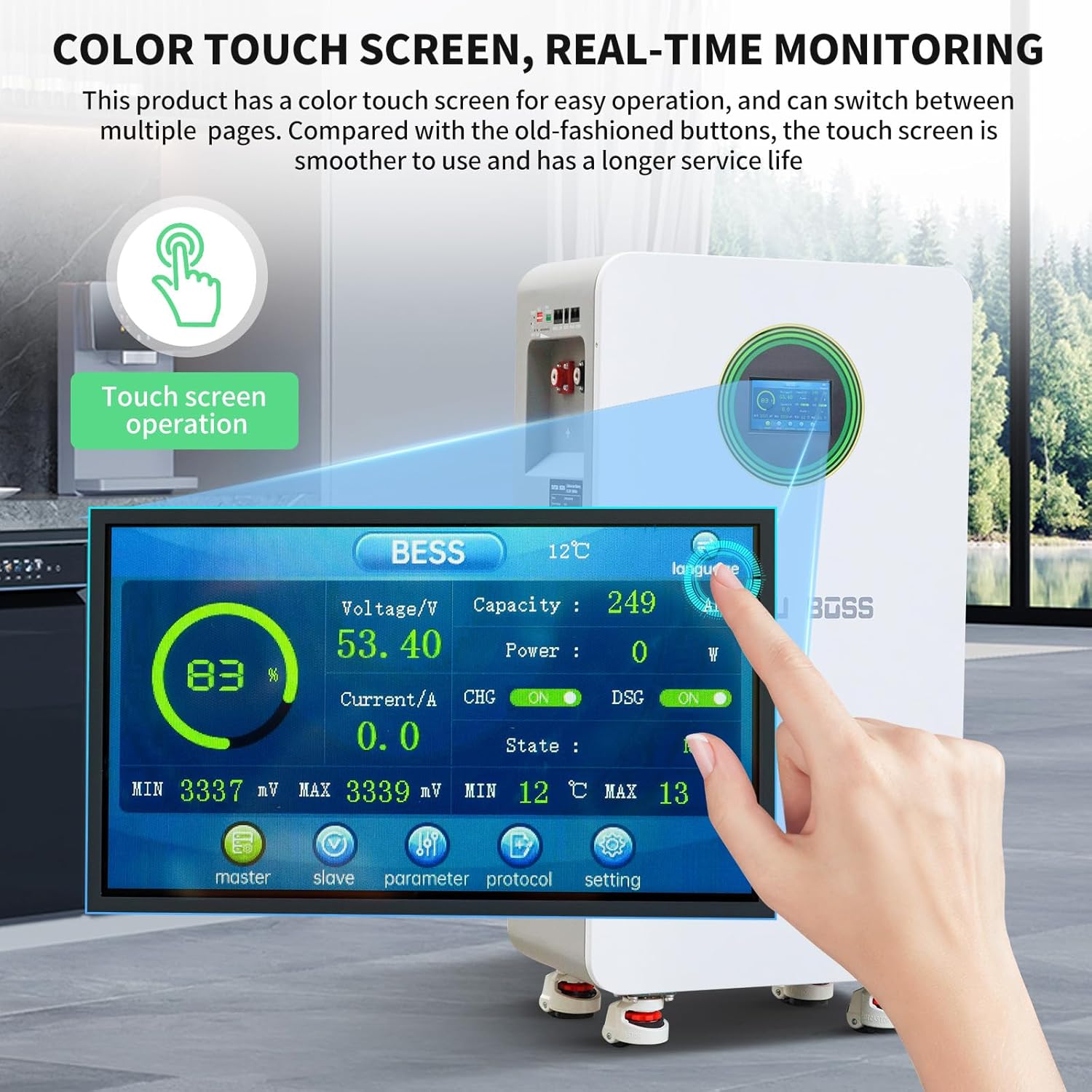
Figure 9: Close-up of the color touch screen displaying real-time battery parameters such as voltage, capacity, power, current, state of charge (SOC), and temperature.
ディスプレイには次のように表示されます:
- 巻tage(V)
- Capacity (SOC %)
- 電力 (W)
- 電流(A)
- 温度(℃)
- BMS Status (CHG/DSG, ON/OFF)
5.3 通信インターフェース
The battery supports RS485, CAN, and RS232 communication protocols for integration with various inverters and monitoring systems. This allows for remote monitoring, control, and parameter adjustments.

Figure 10: Diagram showing the RS485, CAN, and RS232 communication ports and a table defining the pin assignments for each interface.
インターフェース定義テーブル:
| インターフェース | RS485 | できる | RS232 | RS485 | ||||
|---|---|---|---|---|---|---|---|---|
| 機能説明 | Connection to host computer or Inverter | Connection to host computer or Inverter | パラレル通信 | パラレル通信 | ||||
| ピンの説明 | ピン | 説明 | ピン | 説明 | ピン | 説明 | ピン | 説明 |
| 1、8 | RS485-B1 | 1、8 | NC | 1、2、6 | NC | 1、8 | RS485-B2 | |
| 2、7 | RS485-A1 | 2、7 | NC | 3 | TX | 2、7 | RS485-A2 | |
| 4 | NC | 4 | CANH1 | 4 | RX | 4 | NC | |
| 5 | NC | 5 | CANH1 | 5 | グランド | 5 | NC(L)/OUT(R) | |
| 3、6 | グランド | 3、6 | グランド | 3、6 | グランド | |||
6. メンテナンス
- 定期点検: Periodically check the battery for any physical damage, loose connections, or signs of overheating.
- クリーニング: Keep the battery surface clean and free from dust and debris. Use a dry, soft cloth for cleaning. Do not use liquids.
- 換気: 適切な熱放散を可能にするために、通気口が塞がれていないことを確認してください。
- 温度: Operate the battery within the recommended temperature range (0°C to 55°C).
- ファームウェアの更新: 可能な場合は、BMS のファームウェア アップデートを定期的に確認して適用し、最適なパフォーマンスとセキュリティを確保します。
7。 トラブルシューティング
This section provides solutions to common issues. For problems not listed here, please contact customer support.
| 問題 | 考えられる原因 | 解決 |
|---|---|---|
| バッテリーの電源が入らない | Air switch off, push button not pressed, low battery voltage, internal fault. | Ensure air switch is ON. Press the push button. Check battery voltage on LCD. If fault persists, contact support. |
| 出力電力なし | Overload, short circuit, BMS protection activated, loose connections. | Reduce load. Check for short circuits. Verify all connections are secure. Check alarm indicator on LCD. Reset if necessary. |
| Communication error with inverter | Incorrect cable, wrong port, incompatible protocol, incorrect DIP switch settings. | Verify communication cable type and connection. Ensure correct port is used. Check inverter compatibility and protocol settings. Adjust DIP switches for parallel units. |
| バッテリーの過熱 | 換気が悪い、負荷が大きすぎる、周囲温度が高い。 | Ensure adequate clearance around the battery. Reduce load. Move to a cooler environment if possible. |
8. 仕様
The following table details the technical specifications of the DATOUBOSS 48V 300Ah LiFePO4 Lithium Battery.

Figure 11: Key technical specifications of the DATOUBOSS 48V 300Ah Lithium Iron Phosphate battery, including capacity, voltage, current, cycle life, and communication protocols.
| パラメータ | 価値 |
|---|---|
| モデル | 48V 300AhLiFePO4リチウム電池 |
| バッテリー容量 | 15.36kWh (48V 300Ah) |
| 定格オペレーティングボリュームtage | 51.2V(DC) |
| 最大出力電流 | 210A |
| 標準入力電流 | 150A (maximum 210A) |
| ピーク充電電流 | 215A/2秒 |
| ピーク放電電流 | 215A/2秒 |
| Power-off Self Consumption | <300uA |
| バッテリーサイクル寿命(25°C、70% SOH) | ≥8000サイクル |
| バッテリーサイクル寿命(45°C、70% SOH) | ≥3000サイクル |
| 通信プロトコル | RS232、RS485、缶 |
| 寸法(長さ×幅×高さ) | 453 x 260 x 879 mm (17.83 x 10.24 x 34.65 インチ) |
| アイテム重量 | 110 kg (242 ポンド) |
| オーバーボルtag保護 | 58.4V |
| 過充電保護回復 | 54.0V |
| 過放電保護 | 43.2V |
| 過放電保護回復(30秒以内) | 48V(調整可能) |
| 充電高温保護 | 50℃ |
| 充電高温保護回復 | 45°C (adjustable) |
| 充電低温保護 | 0°C (adjustable) |
| チャージクライオプロテクションリカバリ | 5℃ |
| 放電過熱保護 | 50℃ |
| 放電過熱保護回復 | 45℃ |
| 低温保護 | -15℃ |
| 低温保護回復 | -10℃ |
| 充電過電流 | 215A |
| 放電過電流保護 | 215A |
| 短絡保護 | Recovery method: "Charge Removal, Load Removal" |
| 出荷電力量 | 40%から60% |
| 均等化 | 受動的な均衡 |
9. 保証とサポート
DATOUBOSSは 10年間保証 for this battery. This warranty covers quality issues under normal use and service conditions.
For any issues or inquiries, please contact DATOUBOSS customer support. We aim to respond and assist within 24 hours.

Figure 12: Image depicting professional customer support representatives, indicating available assistance for product inquiries.


