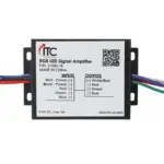
ITC 2300X-KKKK-RV-01 Versi Control Smart System Plus – RV-C

Product Specifications
- Product Name: VersiControl Smart System Plus – RV-C
- Part Number: 2300X-KKKK-RV-01
- Mating Connectors: RV-C DT06-4S
- Power Wires: DTP06-2S
- RGB Wires: DT04-4P
- RGBW Wires: DT04-6P
- Addressable Wires: DT04-3P
Installation Instructions
Safety Instructions
- This device may not cause harmful interference.
- This device must accept any interferences received, including interference that may cause undesired operation.
Wiring Diagrams
Follow the wiring diagram below to wire the module to your system. Note: Maximum replacement fuse size is 20 amps.
- 23002-RGB-RV-01 – Two Standard RGB Zones
- 23002-RGBW-RV-01 – Two Standard RGBW Zones
- 23004-RGB-RV-01 – Four Standard RGB Zones
- 23004-RGBW-RV-01 – Four Standard RGBW Zones
- 23022-RGB-RV-01 – Two Standard RGB/Two Addressable
- 23022-RGBW-RV-01 – Two Standard RGBW/Two Addressable
- 23031-RGB-RV-01 – One Standard RGB/Three Addressable
- 23031-RGBW-RV-01 – One Standard RGBW/Three Addressable
- 23040-RGBW-RV-01 – Four Addressable Zones
FAQ (Frequently Asked Questions)
- Q: What is the maximum replacement fuse size for this product?
A: The maximum replacement fuse size is 20 amps. - Q: Can I mix and match different types of zones in my setup?
A: Yes, you can mix different types of zones according to the available wiring diagrams provided. - Q: Where can I find additional support or contact information?
A: For additional support or contact information, you can reach out to ITC at 3030 Corporate Grove Dr. Hudsonville, MI 49426 or call 616.396.1355. You can also visit itc-us.com for more details.
Safety Instructions
- Disconnect power before installing, adding or changing any component.
- To avoid a hazard to children, account for all parts and destroy all packing materials.
- Do not install any luminaire assembly closer than 6” from any combustible materials.
- Positive (+) outputs require a fuse if the attached wire leads are not rated to handle the max current.
- This device complies with part 15 of the FCC rules. Operation is subject to the following two conditions:
- This device may not cause harmful interference
- This device must accept any interferences received, including interference that may cause undesired operation
Mating Connectors
WIRING DIAGRAMS
Follow the wiring diagram below to wire the module to your system. Note: Maximum replacement fuse size is 20 amps.


3030 Corporate Grove Dr. Hudsonville, MI 49426 Phone: 616.396.1355
itc-us.com
For warranty information please visit www.itc-us.com/warranty-return-policy
Documents / Resources
 |
ITC 2300X-KKKK-RV-01 Versi Control Smart System Plus - RV-C [pdf] Instruction Manual 2300X-KKKK-RV-01, 23002-RGB-RV-01, 23002-RGBW-RV-01, 23004-RGB-RV-01, 23004-RGBW-RV-01, 2300X-KKKK-RV-01 Versi Control Smart System Plus - RV-C, 2300X-KKKK-RV-01, Versi Control Smart System Plus - RV-C, Control Smart System Plus - RV-C, Smart System Plus - RV-C |