 INSTALLATION INSTRUCTIONS
Digital Dimmer
Part#: 21005
PARTS/TOOLS NEEDED:
 |
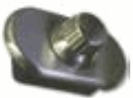 |
| Dimmer Switch | Bezel & Knob (optional) |
 |
 |
| Mounting Screws | Wire Nuts |
 |
|
| Power Drill | |
IMPORTANT SAFETY INSTRUCTIONS. READ CAREFULLY FOR YOUR PROTECTION AND SAVE ALL INSTRUCTIONS.
- Disconnect power before installing, adding or changing any component.
- To avoid a hazard to children, account for all parts and destroy all packing materials.
- It is recommended that fuse protection be added to the positive (+) input.
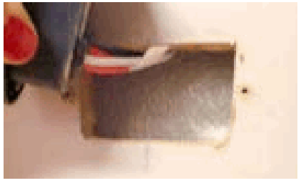
- Determine the installation location for your switch and cut a 1-1/2” x 2” hole using a drywall saw.
- Using wire nuts attached the units’ power to the wires labeled input and attach the output side to your selected light fixture. (figure 1)
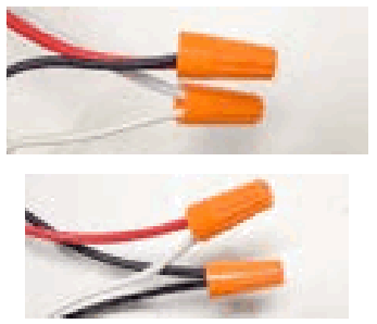
- Feed wires back through the hole and screw the switch in place using the screws provided.
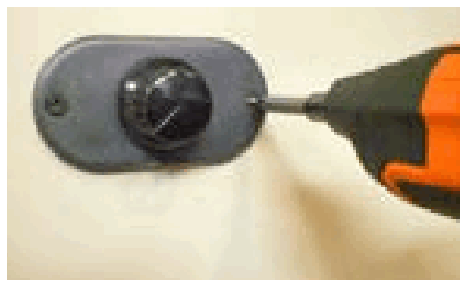
- To attach the bezel, first remove the black knob. Slide bezel onto switch and install new knob.
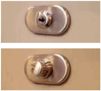
Figure 1: Wire the switch based on the wiring diagram below. 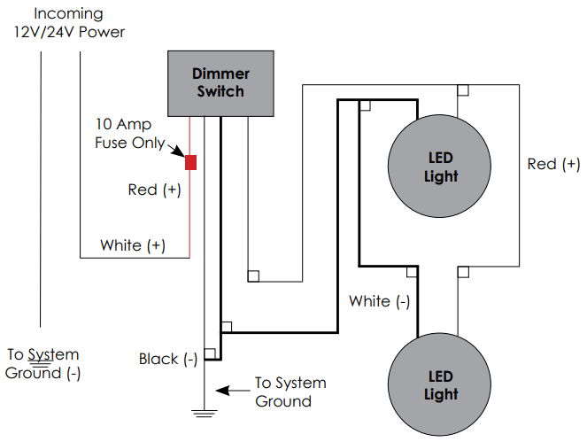
3030 Corporate Grove DrHudsonville, MI 49426
Phone: 616.396.1355
itc-us.com
For warranty information please visit www.itc-us.com/warranty-return-policy
DOC #: 710-00097 • Rev B •11/16/2022
Documents / Resources
 |
ITC 21005 Digital Dimmer [pdf] Instruction Manual 21005 Digital Dimmer, 21005, Digital Dimmer, Dimmer |


