1. Prodotto finitoview
The Murata BLM18PG series chip ferrite beads are designed for noise suppression in electronic circuits. These components function like resistors at noise frequencies, preventing signal waveform distortion while minimizing the possibility of resonance. They are particularly suitable for circuits where stable ground lines are not available, as they do not require an earth connection.
The nickel barrier structure of the external electrodes provides excellent solder heat resistance, ensuring reliable performance in various applications. The BLM_P type features low DC resistance, making it ideal for high-current circuits. This series is designed for general-purpose applications.
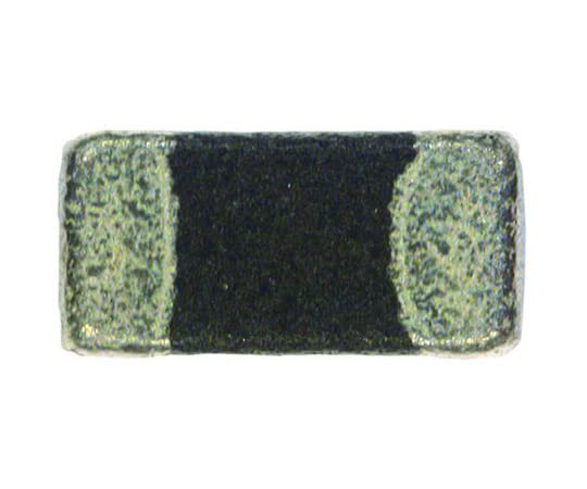
Figure 1: Murata BLM18PG471SN1D Chip Ferrite Bead. This image shows a close-up of the small, rectangular ferrite bead with metallic end terminals.
2. Specifiche
| Parametro | Valore |
|---|---|
| Produttore | MURATA |
| Numero di parte | BLM18PG471SN1D |
| Tipo | Chip Ferrite Bead |
| Tipo di pacchetto | 0603 (1608 milioni) |
| Impedance @ 100MHz | 470 Ohm |
| Corrente nominale | 1A |
| Dimensioni (L×W×H) | Dimensioni: 1.6 × 0.8 × 0.8 mm |
| Lunghezza | 1.6 millimetri |
| Larghezza | 0.8 millimetri |
| Altezza | 0.8 millimetri |
| Materiale | Ferrite |
| Conformità RoHS | Compiacente |
| Quantity per bag | 25 pezzi |
3. Linee guida per l'applicazione
These ferrite beads are surface-mount devices (SMD) and are typically integrated into circuit boards during the manufacturing process. Proper soldering techniques are crucial for reliable performance. Ensure that the component is placed correctly on the solder pads according to the circuit design.
For optimal noise suppression, consider the frequency range of the noise you intend to suppress. The BLM18PG471SN1D offers 470 Ω impedance at 100MHz, making it effective for high-frequency noise. Its low DC resistance (BLM_P type) allows it to be used in power lines or signal lines carrying significant current without causing excessive voltage goccia.
Since these ferrite beads do not require an earth connection, they are suitable for circuits where the earth line is unstable or unavailable. This simplifies circuit design and layout.
4. Principi operativi
Ferrite beads function as frequency-dependent resistors. At low frequencies (e.g., DC or low signal frequencies), they exhibit very low impedance, allowing the desired signal to pass through with minimal attenuation. As the frequency increases, especially into the noise frequency range, the ferrite material becomes lossy, and the bead's impedance significantly increases, effectively attenuating the high-frequency noise.
This characteristic allows the ferrite bead to suppress noise without distorting the signal waveform, unlike a simple resistor which would attenuate all frequencies. The BLM18PG series is designed to prevent signal waveform distortion while simultaneously reducing the possibility of resonance, which can occur with capacitors or inductors.
5. Stoccaggio e movimentazione
To maintain optimal performance and reliability, store ferrite beads in a dry environment, away from direct sunlight and extreme temperatures. Avoid mechanical stress or excessive force during handling and assembly, as this can damage the component or its terminals.
Always handle components with anti-static precautions to prevent damage from electrostatic discharge (ESD), especially when integrating them into sensitive electronic circuits.
6. Informazioni sulla sicurezza
These components are intended for professional use in electronic circuit design and manufacturing. They are small and can pose a choking hazard if ingested. Keep out of reach of children.
When soldering, ensure adequate ventilation to avoid inhaling fumes. Follow all standard safety procedures for handling electronic components and working with soldering equipment.
7. Garanzia e supporto
For specific warranty information and technical support regarding Murata products, please refer to the official Murata Manufacturing Co., Ltd. website or contact their authorized distributors. As these are passive electronic components, their warranty typically covers manufacturing defects under normal operating conditions.
For detailed application notes, reliability data, and further technical inquiries, it is recommended to consult Murata's official documentation and support channels.


