iSecus SDR Counter UAV Digital Module User Manual
Overview
SDR CounterUAV Digital Module is a general-purpose digital RF module based on software radio architecture, which contains two major parts: digital source and power amplifier unit. The digital source part of the FPGA can generate UAV jamming code signals with different digital modulation methods, which are converted into RF signals through the SDR platform and amplified by the power amplifier. The digital source meets the frequency range of 100MHz~6000MHz output, the bandwidth of 200MHz arbitrary configuration, with accurate frequency characteristics. The module can select the corresponding digital modulation jamming code for different UAV types to achieve the best counter effect, supporting ELRS, Crossfire, Flysky, Ocusync, Lightbridge, skyleas and other common protocols for effective jamming. Small form factor, flexible port, simple integration.
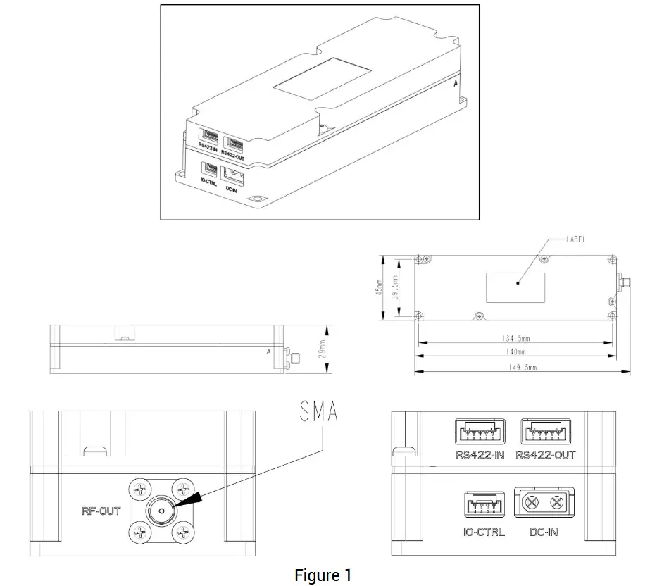
Appearance and Dimensions
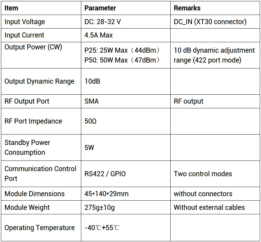
Parameters
Table 1: Product parameters
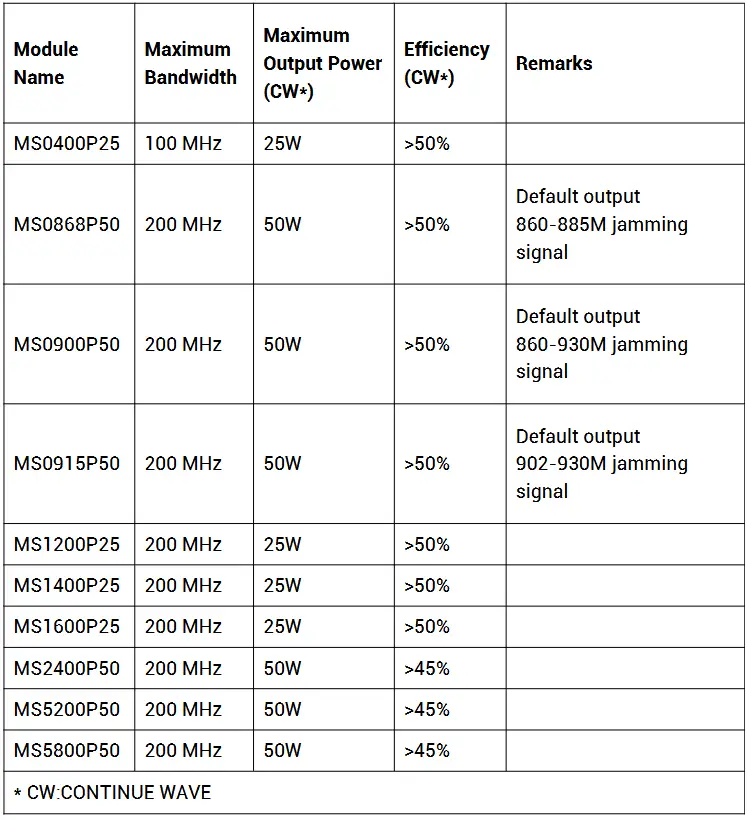
Performance Features
Table 2: Performance features
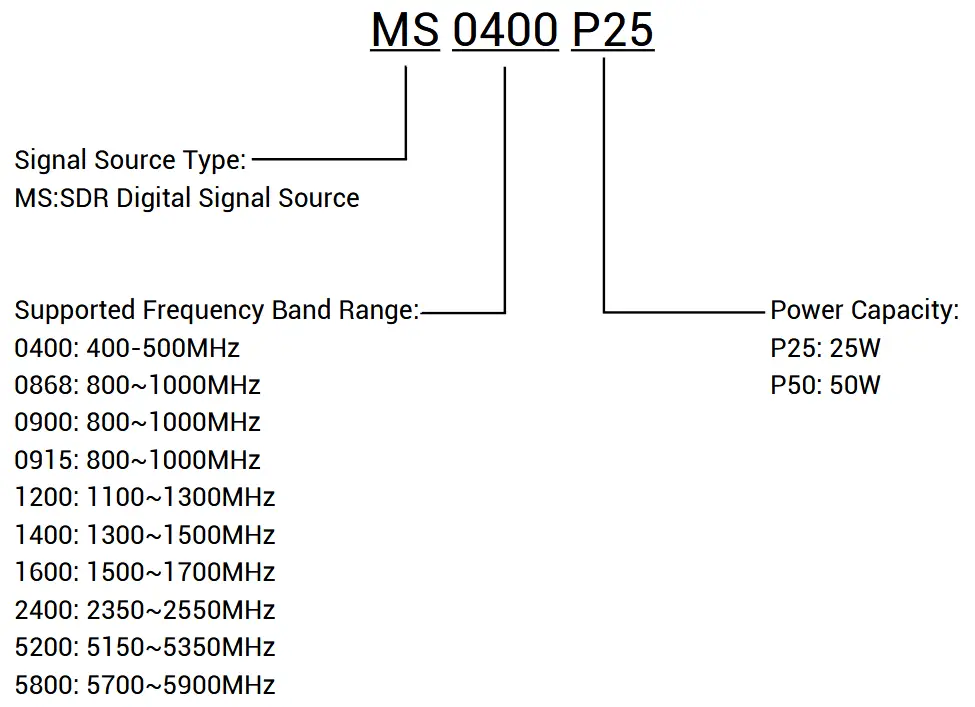
Naming Convention
Functionality
Basic Functions
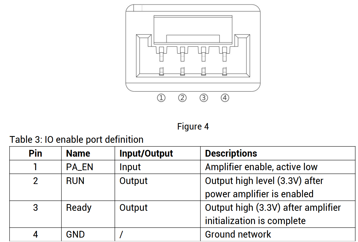
After the module is powered on, wait for the initialization of the module to be completed, and after the Ready signal goes high, the amplifier switch can be controlled through the PA_EN pin.
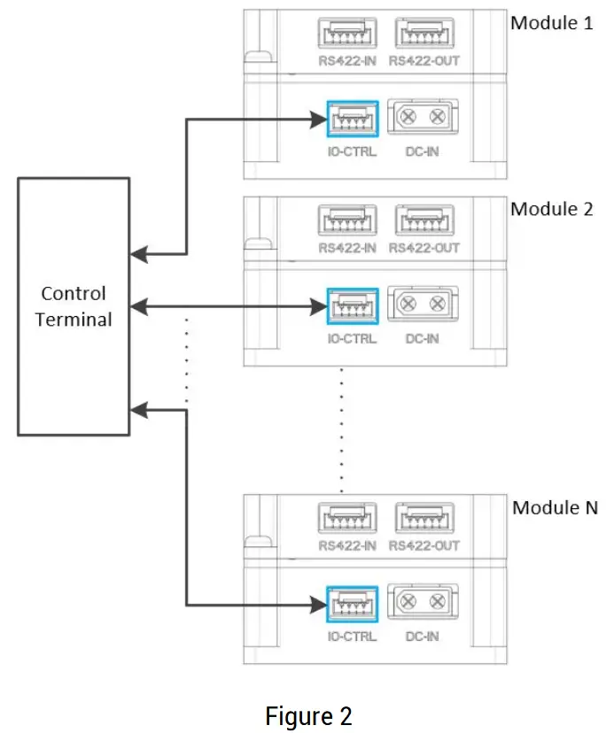
The module has two control ports, IO enable port and RS-422 communication port; IO enable control is simple and convenient for users to integrate and use; RS-422 port in addition to controlling the amplifier.Besides there is access to the module temperature, current and other state parameters, as well as configuration of the digital interference code, so that the product is more flexible and more intelligent. Each module has 2 RS-422 ports, which are used to connect the modules in series and reduce the ports and wiring harness.
(1) IO enable mode wiring diagram
(2) RS-422 port mode wiring diagram

Port Definitions
(1) IO Enable Port: Use GH series 4P connector, the port definition is shown below.
(2) RS-422 Port: Use GH series 5P connector, the port definition is shown below.

(3) Power Supply Port: use XT30 air model port to ensure stable and reliable power supply, the port definition is as follows.

SDR Digital Module Evaluation Kit
Evaluation Kit Instructions
(1) Preparation
1. DC power supply: 28V/5A
2. A computer: win10 and above system
3. SDR digital module evaluation kit
(2) Procedure
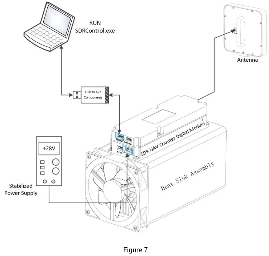
1.Connect the module to the computer according to Figure 7
2.Turn on the +28V power supply
3.Open the upper computer software: SDRControl.exe, the port is as following Figure 8
4.Select the corresponding port, configure the jamming code, and turn on/off the jamming.
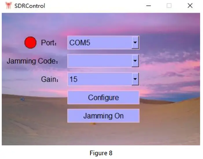
Software Ports
- Port selection: Connected to the serial port after the port appears on the left side of the red indicator dots.
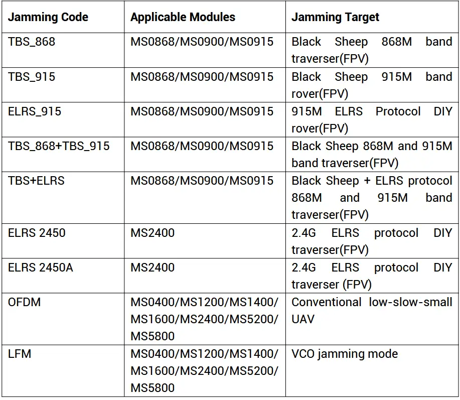
- Jamming code selection: You can select different interference codes corresponding to jam with different targets (optional when the module communication is normal, otherwise the option is blank), the relevant instructions in Table 5.
- Gain Selection: Support 1~15 gain selections, power-on default is the highest 15, step ≤ 1dB, after modifying the gain, press the Configure button to take effect.
- Configuration button: Send the current gain configuration to the module.
- Jamming On button: Turn on jamming.
Jamming Code Loading Instructions
Table 5: Jamming code loading instructions
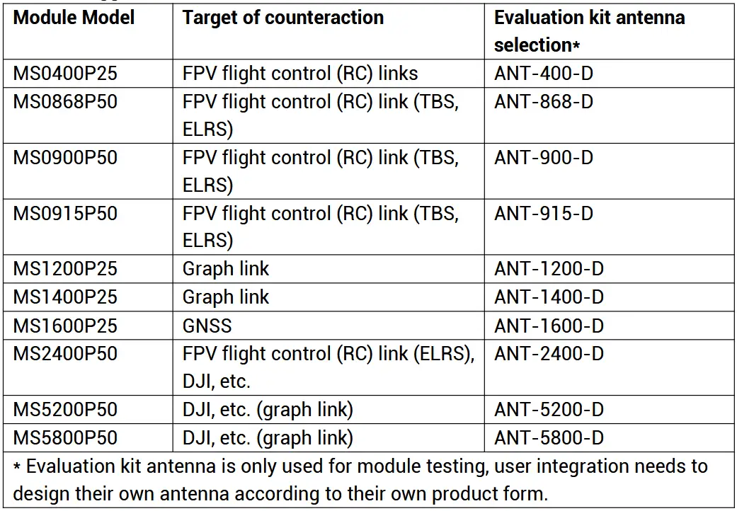
Suggestions for Selection
Table 6: Suggestions for selection
Evaluation Kit Checklist
Table 7: Evaluation kit checklist

Caveats
- The frequency range of the output antenna should be the same as the frequency range of the module, and the non-correspondence of the frequency will lead to the damage of the module.
- The power supply wiring should meet the current requirements and be connected reliably.
- When the module is used, good heat dissipation should be ensured, so as to avoid overheating and causing damage to the module.
- After purchasing the module, please ask for the RS-422 protocol from the professional sales.
Documents / Resources
 |
iSecus SDR Counter UAV Digital Module [pdf] User Manual SDR Counter UAV Digital Module, SDR, Counter UAV Digital Module, UAV Digital Module, Digital Module, Module |