Intellitec Bi-Directional Isolator Relay Delay Installation Guide
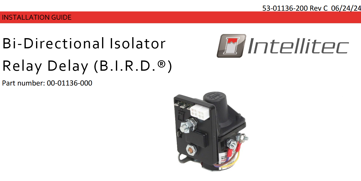
The B.I.R.D.® was designed to make installation simple. With its all in one integrated design, Intellitec brought the electronics to the source, eliminating additional wiring and simplifying the installation process. The B.I.R.D.® has a mounting plate attached with two mounting holes located in the back and uses automotive standard connectors for peripheral connections.
These instructions contain all the information needed to help you install the Battery Disconnect. It is assumed the installer has basic skills in electrical wiring, mechanics, and carpentry. If you have any doubts about these techniques or instructions consult with someone BEFORE you connect a wire or cut a hole.

Wire Diagram 1 illustrates the primary connections of the B.I.R.D.®. 5/16” bolts are used for both battery supplies and are capable of supporting 100A of current.

Wire Diagram 2 illustrates the additional connections on the B.I.R.D.®. Note that the second battery connection is on the opposite side of the device.
Application Connections:

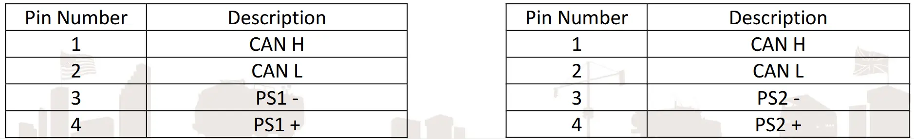
RV-C Connectors:
The RV-C network connections use 4 pin Mini-Fit connectors and follows the RV-C standard pin-out convention described in section “2.1.4 Connectors” of the RV-C guideline.
Locating the B.I.R.D.® Aux Start Switch:
The B.I.R.D.® offers a direct switch input signal that allows the user to bridge the two batteries together for extra cranking power when necessary. This can become very useful if the chassis battery is low or depleted and the vehicle cannot be started. The switch should be readily accessible by the user. This switch not only controls the state of the isolator relay but also provides indication of the state and whether faults have occurred. Ensure the wall used for mounting the switch has enough clearance behind it to allow cables access. Typically, ¾” to 1” is required.

Note: Drawing dimensions refer to the switch used in the Intellitec kit (part # 10-01136-000).
Installing the B.I.R.D.®:
WARNING: Before proceeding, disconnect all sources of power. Unplug the shore power cable and turn off the generator. Disconnect the battery(s) negative (-) terminal.
The B.I.R.D.® controls a relay that acts as electro-mechanical switch that disconnects the battery. It should be located near the batteries for wiring simplicity. When installed, the relay will be inserted “in-line” between the two battery banks positive (+) terminals. Keep this in mind when choosing the installation location.
While holding the relay in place near the battery banks, mark the location of the two holes for the relay mounting bolts. Set the relay aside, and drill two mounting holes. Before bolting the relay in place, route the Control Cable near the mounting place. When installing in an engine compartment, be sure to provide sufficient space for airflow to allow for cooling.
Connecting the Cables:
WARNING – Torque requirements for the high-power Battery Positive terminal 4-5 FT-LBS and Primary Load contact studs should be 5 – 7 FT-LBS. When connecting the primary load wires (Copper Stud), you must use two wrenches (One open-ended low profile and one torque wrench) to tighten the nuts on the stud, use the torque wrench to turn the outside nut and the open-ended low profile to hold the nut on the inside from turning. The copper stud must not turn, or relay operation may be affected.
Locate the positive battery cable for the chassis battery. Carefully cut the cable near the relay. Strip the cable insulation back about 1/2″ on each end and crimp on the battery cable terminals defined in the Application Connections table. Remove keps nuts from both copper studs and connect the terminals to the copper studs on the relay. It’s important that the “Battery Positive” and “Primary Load” signals defined in Table 1 go to the studs defined in Wire Diagram 1 and 2.
If using the provided B.I.R.D.® Switch Harness Kit (10-01136-000), follow Wire Diagram 2 for matching the wire harness colors to the connectors.
The B.I.R.D.® has 2 RV-C ports. One of these ports provides battery source 1 power while the other provides battery source 2 power. This feature offers a more advanced network management option. Refer to Wiring Diagram 2 to ensure proper connection of the RV-C network.
After all wires have been connected and tightened properly, reconnect the batteries negative cable.
Verifying Operation:
To verify the B.I.R.D.® is powered up, check for the green LED heartbeat on the device. This will illuminate right above the company logo.
If using the provided switch with the Intellitec kit 10-01136-000 toggle the state of the disconnect. If the LED ring on the switch is illuminated then the isolator relay is closed is closed, if the LED ring on the switch is not illuminated then the isolator relay is open.
When using this device in an RV-C network use the DC DISCONNECT DGN to change the state of the isolator relay. Refer to the 53-01136-300 – Integrators Guide for specific information regarding the status and control of the B.I.R.D.®.
Available Product Literature and Guides:
Brochure: 53-01136-000
Product Specification: 53-01136-001
User’s Guide: 53-01136-100
Installation and Applications: 53-01136-200
Integrators Guide: 53-01136-300
Contact Information: www.intellitec.com
Intellitec Products, LLC
1485 Jacobs Road, DeLand Florida, USA 32724
Documents / Resources
 |
Intellitec Bi-Directional Isolator Relay Delay [pdf] Installation Guide Bi-Directional Isolator Relay Delay, Bi-Directional, Isolator Relay Delay, Relay Delay, Delay |