Intellitec 01141 Road Commander Module
Description
Intellitec Road Commander modules are configurable to accommodate a wide variety of operational needs and conditions. While the configuration procedure is simple, specific procedures should be followed.
Programming Connections
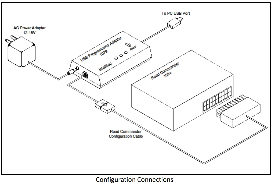
Road Commander module programming is accomplished using an Intellitec 00-01079-000 USB programming adapter, Road Commander configuration cable adapters, a power adapter, and a PC running the iCAN Configuration tool. Please see the connection diagram below. Note that the module is powered and programmed via the USB programmer. No additional power supply to the module is required or recommended.
Step-by-Step Instructions
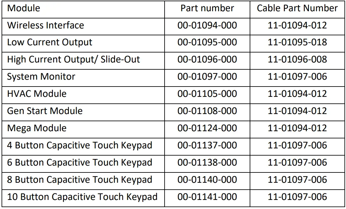
- Select the Road Commander configuration cable. There is a unique configuration cable for each Road Commander module. See Table.
- The rectangular connector on the configuration cable must match the connector on the Road Commander module.
- Insert the flat connector on the configuration cable into to USB programming adapter cable.
- Insert the other end of the configuration cable into the Road Commander module.
Note: For the 1096 High Current / Slide-Out module, quickly connect the terminal on the cable to “Battery Positive” on the module. - Confirm switch on the USB programming module is set to “RS232”.
Note: Programmer MUST be set to RS232 to successfully program the module. - Plug the AC power adapter (12V) into to USB Programming adapter.
- Plug the AC power adapter into the AC outlet.
- Connect the USB programming adapter to the PC using the USB cable provided.
- Open the Road Commander configuration application on your PC by clicking on “iCAN Config GUI”.
- Assign settings as needed. See Road Commander module documentation.
- Select “Comm/Write Configuration” to transmit data to the module.
- Confirm status window indicates success.
- Disconnect the configuration cable from the Road Commander module.
- Repeat as needed for additional modules.
Product Specifications
- Wireless Interface
- Low Current Output
- High Current Output/ Slide-Out System Monitor
- HVAC Module
- Gen Start Module
- Mega Module
- 4 Button Capacitive Touch Keypad
- 6 Button Capacitive Touch Keypad
- 8 Button Capacitive Touch Keypad
- 10 Button Capacitive Touch Keypad
Step-by-Step Configuration Procedure
- Select the appropriate configuration cable based on the Road Commander module you are configuring.
- Ensure the rectangular connector on the configuration cable matches the connector on the Road Commander module.
- Insert the flat connector of the configuration cable into the USB programming adapter cable.
- Connect the other end of the configuration cable to the Road Commander module.
- Select “Comm/Write Configuration” to transmit data to the module.
- Confirm that the status window indicates a successful transmission.
- Disconnect the configuration cable from the Road Commander module.
- Repeat the process for additional modules as needed.
Frequently Asked Questions
Q: Can I use the same configuration cable for all Road Commander modules?
A: No, each Road Commander module requires a unique configuration cable. Refer to the provided table for the correct part numbers.
Q: How do I know if the data transmission was successful?
A: After selecting “Comm/Write Configuration,” check the status window for a success indication. If successful, you can proceed with disconnecting the cable.
Documents / Resources
 |
Intellitec 01141 Road Commander Module [pdf] Instruction Manual 00-01094-000, 00-01095-000, 00-01096-000, 00-01097-000, 00-01105-000, 00-01108-000, 00-01124-000, 00-01137-000, 00-01138-000, 00-01140-000, 00-01141-000, 01141 Road Commander Module, 01141, Road Commander Module, Commander Module, 01141 Module |