Intellian OW70L OneWeb LEO User Terminal
Specifications
- Product Name: OW70L (P-P) – OneWeb LEO User Terminal
- Function: Dual Antenna System with fail-safe operation
- Feature: Embedded dual antenna mediator
Product Usage Instructions
- Configuration of Dual Antenna System:
- Make sure the antenna system components are properly installed as per the details in section 6.2 of the manual.
- Accessing LUI:
- To establish communication between Compound UT#1 and Compound UT#2:
- Connect an ethernet cable from the MGMT port on CNX to a LAN port of a PC.
- Setting the Compound UT#2 (Secondary):
- Turn on UT#2’s POWER switch on CNX and wait for system startup.
- Select Install and navigate to Installation Navigation.
- Select Compound UT#2 (Secondary) and click Submit to apply the settings.
- Access LUI using the changed ip address (192.168.100.10).
- Go to Diagnostics > Compound UT Info to verify the Secondary role.
- Setting the Compound UT#1 (Primary):
- Turn on UT#1’s POWER switch on CNX and wait for system startup.
- Select Install and navigate to Installation Navigation.
- Select Compound UT#1 (Primary) and follow the steps as done for UT#2.
FAQs
- Q: What should I do if the MoCA indicator does not turn on after turning on the POWER switch?
- A: Check the cable connection status and try turning the CNX power off and on again. If the issue persists, refer to troubleshooting steps in the manual.
“`
Precautions
Chapter 1. Precautions
Prior to installation, read this Installation Guide carefully including the safety warnings and information.
Failure to do so could result in serious injury or inoperability of the terminal.
Antenna installation must be provided by a suitably trained professional installation technician or bya
qualified antenna installation service. Installation is not to be attempted by someone not trained or
experienced in this type of work.
1.1 Warnings, Cautions, and Notes
WARNING, CAUTION, and NOTE statements are used throughout this manual to emphasize important and
critical information. You must read these statements to help ensure safety and to prevent product damage.
The statements are defined below.
WARNING
WARNING indicates a potentially hazardous situation which, if not avoided, could resultin
death or serious injury.
CAUTION
CAUTION indicates a potentially hazardous situation which, if not avoided, could result
in minor or moderate injury or damage to equipment. It may also be used to alert
against unsafe practices.
NOTE
A NOTE statement is used to notify people of installation, operation, programming, or
maintenance information that is important, but not hazard-related.
1.2 General Precautions
Before you use the antenna, make sure that you have read and understood all safety requirements.
THIS WAY UP
• Place the boxes/crates on the floor with the arrow pointing up.
FRAGILE
• Since the Radome is fragile, handle it with care. Do not apply excessive pressure or
shock. These may cause surface cracking or other damage.
DO NOT STACK
• Do not stack boxes/crates as there is a risk boxes/crates may fall and be damaged.
KEEP DRY
• Always make sure the antenna is stored on a dried floor.
• The antenna can withstand ordinary rain. However it water resistance cannot be
guaranteed if submerged.
• Keep the antenna in dried place for sufficient ventilation. Do not store the antenna
wrapped in a tarp, tent, vinyl, and others.
* DO NOT SHIP VIA RAIL: Ensure not to ship any system via Rail.
• Before you begin a site installation, check the appropriate electrical code requirements and with other
regulations governing this kind of installation within the country of use.
• When installing, replacing, or disconnecting any cable components, make sure that each exposed metal
connector of the antenna is grounded firmly before the work.
• The outdoor antenna and antenna cables are electrical conductors so transients or electrostatic
discharges may occur at the antenna during thunderstorms. If the antenna is not installed properly, the
electronic equipment may be damage and/or cause personal injury or death to persons touching the
exposed metal connectors of the electronic equipment.
• Avoid installing the antenna at high-voltage arc-over place where there is any possibility of service drops
to buildings.
• Do not climb the tower during a thunderstorm or in windy, wet, icy, or snowy conditions.
• Do not touch antennas, surge arrestors, or antenna cables during a thunderstorm.
• ODE (Outdoor Equipment) must be properly mounted and secured to the tower. Failure to do so could
result in detachment of the unit, causing disruption in the unit’s operation or could result in the unit
falling, which could cause serious injury or death.
• When installing the antenna, remember;
– DO NOT use a metal ladder.
– DO dress properly: wear rubber gloves, shoes with rubber soles and heels, and a long sleeve shirt or jacket.
Introduction
Chapter 2. Introduction
2.1 Introduction to OW70L-Dac
The OW70L-Dac is a dual parabolic terminal with a 73 cm reflector size based on a 12.3 dB/K G/T which can beoperated in the OneWeb low earth orbit (LEO) satellite constellation. The OneWeb communications networkcomprises terrestrial gateways positioned around the globe communicating with OneWeb user terminals. Aradio link to the satellites is established using the User Terminal (UT) operating in the Ku-band, with uplink frequencies between 14.0 and 14.5 GHz, and downlink between 10.7 and 12.7 GHz. The antenna provides Internet access via the OneWeb satellites and OneWeb gateways.
2.2 OW70L-Dac Features
• LEO satellite scan and tracking algorithm.
• 3-axis stabilization platform with motion drift compensation solutions.
• Fully sealed to protect against outdoor environment.
• Dual-dome operation for blockage mitigation.
• Single IP allocation to common user device behind CNX when UTs are paired for blockage mitigation to enable seamless IP-switching across UTs.
• Simple and suitable industrial design for professional installation.
• Wideband GNSS antenna improves location precision.
• Provides secure connections over GigE between router and BBU or Cell-site router.
• Remote monitoring, diagnostics and trouble-shooting to resolve issues on site, which is made available to the end user via a local management interface.
• Ability to store multiple software versions to fallback to a known good or factory version in case of errorsin the current working version of software.
Planning Installation
Chapter 3. Planning Installation
CAUTION
Be sure to complete the pre-installation checklist before you begin installing the antenna. Refer to
“10.1 Appendix A. Pre-Installation Checklist” on page 46.
3.1 Installation Precautions
The User terminal installation requires extreme precaution and safety measures given the installation
environment. Failure to follow the correct installation process may lead to injury of the installer and/or cause
damage to the system. In order to maximize the performance of the system, a thorough review of this
installation guide is strongly recommended, as well as executing the installation process as it is noted in this
manual.
To ensure your own safety and convenience of installation, note the following precautions.
• Review the general safety precautions in the Safety Precautions chapter.
• Familiarize yourself with the antenna and the mounting instructions prior to climbing any roof or ladder.
• Verify that all safety measures for outdoor or rooftop installation are arranged.
• Test all requirements before beginning the actual installation to determine if the equipment and
necessary items are available and functioning properly.
• Install the grounding system for the antenna tower, radio hardware, and surge arrestor before connecting
the cable from the equipment to the surge arrestor. This protects the system against lightning strikes
during installation.
3.2 Selecting Installation Site
Before installing the antenna system, consider the best place to position the antenna for both performance
and safety.
3.2.1 Installation Location for Antenna
The antenna should be placed in an area with little to no RF signal blockage. A safe mounting place and a
restricted access location should be selected.
When the antenna is transmitting, obstacles in way of the beam path will decrease the satellite signal
strength. The antenna unit should have direct line-of-sight with the desired satellite without any obstacles in
the beam path. Certain minimum distances between the antenna and other onboard devices must also be
considered during installation.
3.2.2 Installation Location for CNX
An ideal location for the CNX should be:
• Within 100 m (300 ft) of the antennas
• In a dry, cool and ventilated location
• Within close proximity to the digital and analog interface
• Close to a power source
3.2.3 Minimizing Satellite Blockage
The ideal antenna site should have a clear view of the horizon or of the satellite with all-around clearance.
Some examples of obstacles you must avoid for the directional antenna to operate effectively are:
neighboring buildings, trees, or other obstructions and power lines. To minimize the influence of obstacles,
signal interference, or reflections, note the following guidelines:
• Avoid trees in the signal path. Seasonal changes such as leaves or hanging icicles can impact signal
absorption. Mount the antenna as high as possible above the ground to free up space. In open areas,
the ground is the actual surface of the earth.
• To use the basic antenna system you need to install two antennas. Intellian recommended Installing the
antenna at least 1.53 m (60.23″) away from the other antenna.
• Make sure there are no obstacles within 53 degrees from Zenith. Obstacles can interrupt the satellite
signal transmission and reception of the antenna.

3.2.4 RF Hazard Precautions
The Federal Communications Commission has adopted a safety standard for human exposure to RF (Radio
Frequency) energy, which is below the OSHA (Occupational Safety and Health Act) limits. To comply with
current FCC RF Exposure limits, the antenna must be installed at or exceeding the minimum safe distance
as guided by the antenna manufacturer or supplier.

ARNING
Exposure to radio frequency energy (RF) from the antenna may cause thermal injuries including
tissue damage from increased heating and body temperature. Keep everyone at a safe distance
from the antenna when the system power is ON. Personnel must maintain a minimum distance
of A (refer to the table below) from the antenna and installers must place the ODE (Outdoor
Equipment) transmitter in a manner to maintain minimum spacing requirement. Failure to do
so could result in exposure to radio frequency energy (RF) transmitted from the ODE (Outdoor
Equipment) that could result in serious injury or death.
The value of the table applies to persons in the general population who are in an uncontrolled
environment.
For General population/Uncontrolled exposure 1.0 mW/cm2
Reflector Size (mm) Antenna Gain A Minimum Distance (m (ft))
*730 mm 38.5 7.50 (24.60)
*The minimum distance values for radio frequency energy (RF) depend on the reflector size of the
antenna. Confirm your reflector size of the antenna.
3.3 System Package
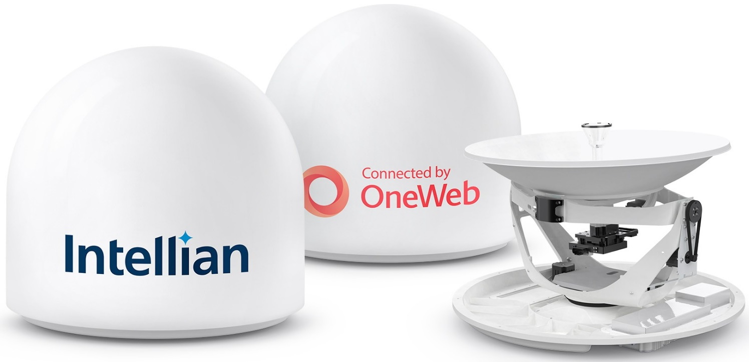
3.3.1 Above Deck Unit (ADU)
The OW70L-Dac operates in a dual parabolic primary and secondary configuration. Each terminal consists
of apedestal, a reflector, RF modules and antenna control modules which are enclosed in a radome.
• Pedestal: 3-axial stabilized platform for the position compensation of the antennas
• RF modules: the antenna consists of a reflector, OMT, feeder and RCM which converts the satellite
signals into the IF bands and up-converts IF bands to the forward-link satellite signals. The primary
antenna includes the modem module, called SSM, which implements necessary functionality to transmit
and receive signals as well as communicate and command pointing directions to the antenna.
• Control modules: the antenna interface module, called AIM, controls the antenna motion by interfacing
with the modem and RF modules.
• Radome: protects the antenna from outdoor environment.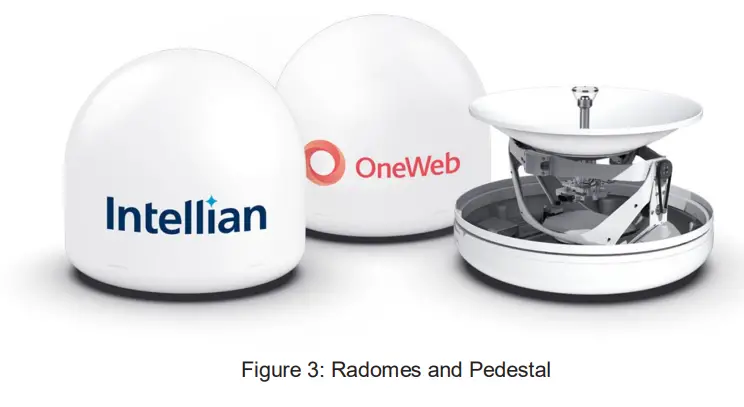
3.3.2 Customer Network Exchange (CNX)
The Customer Network Exchange (CNX) must be installed in a weather-protected area. It interfaces with user equipment and provides power and data interconnection. The CNX connects to primary antenna while providing secure GigE connection to the Baseband Unit. The CNX takes 48 V input but can vary by product variant.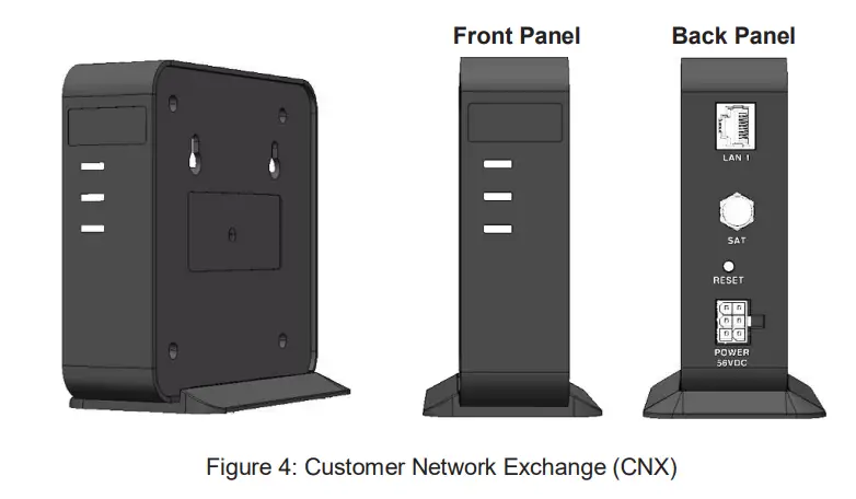
3.5 Unpacking System Package
Follow the steps for easy and safe unpacking. The system package consists of two packages that a Primary
Antenna Package (Box 1) and a Secondary Antenna Package (Box 2).
1. Bring System Packages (Primary Antenna Package(Box 1) and Secondary Antenna Package (Box 2)).
2. Remove the top cover and
Installing Above Deck Unit ADU
Chapter 4. Installing Above Deck Unit (ADU)
4.1 General Requirements
4.1.1 Tower Construction Requirements
The antenna is designed to be installed on a cell tower, mostly monopole type but some lattice or guyed
towers or buildings are also in consideration. To accommodate the antennas, the antenna tower must
satisfy the following requirements:
• Ensure that the construction of the tower consists of sturdy, weatherproof, and non-corrosive material
(e.g. stainless or galvanized steel construction pipe).
• The recommended mounting height of the antennas is about 6m above the ground level and each
antenna will, desirably, be mounted approximately 1 m out from the pole.
• Make sure that the tower is free from any substance which may prevent a good electrical connection
with the antenna.
4.1.2 Antenna Mounting Requirements
You need to procure or fabricate a suitable mounting plate and tower to support the ODE (Outdoor
Equipment).
Consider the following factors to select the mounting method:
• The physical size of the unit (770 mm (30.31 inch) high by 730 mm (28.74 inch) diameter)
• The weight of the unit (30 kg, 66.13 lbs)
• The mechanical resonance of the system excited by: wind induced vibration (5 Hz)
• The system operates in primary-secondary mode. To mount dual antennas on a single tower, ensure
there is <100 ft separation between domes.
• The preferred installation orientation is East to West.
• Ensure the antenna is levelled ±1° in elevation and ±5° from the True North axis.
4.2 Antenna Dimensions
Confirm the height and diameter of the antenna unit shown in the following figure before installing it.
The mounting surface and overall space occupied by the radome must be sufficient for the height and
diameter of the fully constructed radome on top of its mounting base. The primary and secondary radome
dimensions are the same.
Unit: mm (inch)
4.3 Placing Antenna on Tower
4.3.1 Leveling Mounting Plate
Make sure the horizontal pole and mounting plate are almost parallel to the surface (precondition) using
leveling tools.
Mounting
Plate
HHoroizroinztaolnPotalel Pole
in(
s
i
tnals
le
t
daol
nletdhe Tt
ooweTrower)
Earth Coordinate
Surface
4.3.2 Marking True North Point on Mounting Plate
A. When using a magnetic compass:
1. Measure the orientation of the magnetic north by using a compass.
2. Mark the magnetic north point on the mounting plate.
3. Get the magnetic declination angle at the installation area by the calculator (Refer to the Magnetic Field
Calculators on the National Oceanic and Atmospheric Administration (NOAA) website www.ngdc.noaa.gov.
4. Mark the True North point on the mounting plate by including the declination angle.
B. When using a true north indicator:
Mark the True North point on the mounting plate by using the true north indicator.
4.3.3 Placing Antenna on Mounting Plate
1. Fasten the lifting straps (separate purchase) to the antenna unit. Check the condition of the lifting strap
and ensure the shackle is tightened up. Lift the antenna above the mounting plate using a crane and
carefully lower down the antenna toward the mounting plate.
2. Check the Arrow Mark on the bottom radome.
3. Place the antenna on the mounting plate. Align the Arrow Mark to the True North point (marked in the
previous step) of the mounting plate. The antenna must be correctly aligned during installation or after
major repairs to perform properly.
Lifting Straps
(separate purchase)
Arrow Mark
True North
Figure 6: Placing Antenna on Mounting Plate
CAUTION
Ensure the antenna is mounted within ±5° azimuth and ±1° elevation.
WARNING
When moving the antenna, it may sway by windy. Be careful when handling the antenna.
OW70L (P-P) – OneWeb LEO User Terminal
Chapter 7. Starting Dual Antenna System
The OW70L has the embedded dual antenna mediator function, which is used to instantly switch between two antenna systems. When one antenna loses line of sight to a satellite, the other antenna will immediately provide a fail-safe operation to maintain the highest levels of system performance and reliability. This ensures always-on broadband service by reducing the out of service time.
7.1 Configuration of Dual Antenna System
To use the Dual Antenna System, make sure the antenna system components are properly installed. Refer to “6.2 Antenna System Configuration” on page 38 for more details.
7.2 Accessing LUI
To establish Dual Antenna System communication between the compound UT#1 (operate as the primary) and the compound UT#2 (operate as the secondary), follow the steps below. Connect an ethernet cable from the MGMT (Management) port on the front panel of CNX to a LAN port of a PC.
CNX- E Front Panel
MGMT (Management) Port PC (Not supplied)
Figure 14: Front Panel LAN Port Connection with CNX
42
Starting Dual Antenna System
7.2.1 Setting the Compound UT#2 (Secondary)
First, the Compound UT#2 (Secondary) should be set and then the Compound UT#1 (Primary). 1. Turn on the UT#2’s POWER switch on the front panel of the CNX, and then wait a few seconds for
system startup. The MoCA indicator light on the CNX display will turn green.
NOTE If the MoCA indicator does not turn on after five minutes during step 1, check the cable connection status and try to turn the CNX power off and on again.
Power On/Off MoCA
Switch
indicator
2. Use the following IP address to access LUI page. · IP Address: 192.168.100.1 (Default) NOTE The LUI should be accessed by Chrome web browser when setting a CUC (Compound UT Controller) role.
3. Select Install on the navigation bar, and then go to the Installation Navigation. 4. Press Back or Next button on the Installation Navigation until the Select Installation Role is reached. 5. Select Compound UT#2 (Secondary) on the Select Installation Role option to activate the function.
Then click the Submit button to apply the settings to the system. LUI will automatically reboot.
3
4
5 5
43
OW70L (P-P) – OneWeb LEO User Terminal
6. Try to access the LUI again using the changed Compound UT#2 (Secondary) ip address (192.168.100.10).
7. Go to Diagnostics Compound UT Info to verify the Secondary of CUC (Compound UT Controller) role on the Compound UT Info.
6
7
7
NOTE
If you cannot see the “Compound UT Info” menu on “Diagnostics” in the 6th step, check the CUC role’s settings and try to start the first process again.
7.2.2 Setting the Compound UT#1 (Primary)
The Compound UT#1 (Primary) should be set after setting the Compound UT#2 (Secondary).
1. Turn on the UT#1’s POWER switch on the front panel of the CNX, and then wait a few seconds for system startup. The MoCA indicator light on the CNX display will turn green.
Power On/Off MoCA
Switch
indicator
NOTE If the MoCA indicator does not turn on after five minutes during step 1, check the cable connection status and try to turn the CNX power off and on again.
2. Use the following IP address to access LUI page. · IP Address: 192.168.100.1 (Default) NOTE The LUI should be accessed by Chrome web browser when setting a CUC (Compound UT Controller) role.
3. Select Install on the navigation bar, and then go to the Installation Navigation. 4. Press Back or Next button on the Installation Navigation until the Select Installation Role is reached.
44
Starting Dual Antenna System 5. Select Compound UT#1 (Primary) on the Select Installation Role option to activate the function.
Then click the Submit button to apply the settings to the system. LUI will automatically reboot and then display the Diagnostics page.
3 4
5 5
6. Go to Diagnostics Compound UT Info to verify the Primary of CUC (Compound UT Controller) role on the Compound UT Info.
6
6
NOTE If you cannot see the “Compound UT Info” menu on “Diagnostics” in the 6th step, check the CUC role’s settings and try to start the first process again.
45
OW70L (P-P) – OneWeb LEO User Terminal
7.3 Starting Install Menu (Install Wizard)
The Install Wizard will guide you through the setup steps for the antenna system commissioning. We highly recommend using this wizard to complete the installation and commissioning of the system. After accessing LUI main page, go to the Install menu on the navigation bar and perform the wizard. The LUI Installation page serves as the front end for installation.
ü Initial Install Page The first page of the installation process is a splash screen that states that the UT has not yet been installed. To proceed with the installation to the next step, click on Start Installation. On the right are three buttons: · Start Over button: Brings you back to the first step of the installation. · Back button: Steps one step back in the installation. · Next button: Advances to the next step in the installation.
1
2
3
ü Step 1: Upload Software Bundle
The Upload Software Bundle page displays the current software versions running on each component. When uploading a software bundle, the software mode should be factory. (Refer to “8.9.2 Switch UT Software” on page 88 for more details.) 1. Clicking on the empty text box or the Browse button allows the upload of a Software Bundle. 2. Until a bundle has been uploaded, the Upload button is greyed out. If the upload is not successful, a
status error message will be displayed.
46
Starting Dual Antenna System ü Step 2: Upload Ephemeris Data The Upload Ephemeris Data page is a simple file upload page. Simply click on the empty text box or the Browse button to upload an Ephemeris file. Until a file has been uploaded, the upload button is greyed out. Upon a successful upload, a success status message will be displayed, and the state can be advanced. Click on Next.
NOTE What is Ephemeris Data? Ephemeris Data contains current information about the orbits of the satellites in the OneWeb constellation. The User Terminal uses ephemeris data to determine the positions of the satellites in the sky at any given time. Remark: Every 30days, this data file is updated. Once the User Terminal is commissioned this will be updated automatically. ü Step 3: RF Cable Setup The IF Cable Type and IF Cable Length(m) on the Internal is pre-set with a default value depending on the RF cable. Make sure that is the same with the following default values. Click the Next button to go to the next step. · IF Cable type : SS405 · IF Cable Length(m) : 2.24
47
OW70L (P-P) – OneWeb LEO User Terminal ü Step 5: Configure Blockage Zones It is optional to set up the blockage zones for the system. Each antenna can be configured up to 10 blockage zones with transmission muted. Click the Add more blockage zones to configure additional blockage zones. · Azimuth Min/ Max : The Azimuth Min is the relative azimuth angle where the blockage starts, and the
Azimuth Max is the relative azimuth where the blockage ends (Range: 0 ~ 360). · Elevation Min/Max: The Elevation Min/Max is the elevation angle where the blockage is set (Range: 0 ~
90). The blockage is activated below the elevation angle. · Antenna ID: Enter the value of 0. · Transmission prohibited? : Set whether to activate a TX mute or not (Yes/No). Click the Submit button to apply the settings to the system.
1 2 3 4
48
Starting Dual Antenna System
NOTE · When setting a blockage zone, both “Blockage zones” and “No transmit zones” should be considered.
– Blockage zones : Zones where obstructions can inhibit or degrade satellite communication – No transmit zones : Areas where transmit power is potentially dangerous for persons
N
Blockage Zone
Blockage Zone
Blockage Zone with no-transmit zones, azimuth (example)
Blockage Zone with no-transmit zones, Elevation (example)
· If Blockage zone is set, you can see the status at LUI > Antenna > Blockage Zones menu.
· To get a blockage zone value, you should install the Theodolite application on an iOS device. Intellian recommends using the Theodolite application.
ü Step 6: Antenna Levelling Click the Next button to go to the next step.
49
OW70L (P-P) – OneWeb LEO User Terminal ü Step 7: Autonomous States Autonomous states all display a progress bar of its progress. The following states require no action from the user aside from proceeding to the next state. All installation states are displayed, or some installation status is displayed underneath the progress bar.
ü Step 8: Installation Complete & Result The configuration result is displayed. Toggle activation button to the right position on each result row to see the results. This completes the steps of the wizard.
50
Starting Dual Antenna System
7.4 Monitoring Dual Antenna System
You should monitor the performance of the dual system via LUI. To monitor the dual system, position two windows side-by-side and then access LUI using ip address for each compound UT.
Compound UT#1 (Primary)
Compound UT#2 (Secondary)
51
OW70L (P-P) – OneWeb LEO User Terminal
Chapter 8. Using Local User Interface (LUI)
8.1 Introduction
With the embedded Using Local User Interface (LUI) software, the antenna can be monitored, controlled, and diagnosed remotely through a web browser. It saves time and cost generated by maintenance activities such as operating firmware upgrades, tracking parameter resets, and system diagnosis, etc.
8.2 Turning On System
The antenna has to be connected to the CNX and powered up in order to access the webpage. The CNX should be connected to a power adapter before connecting between the antenna and CNX.
52
8.3 Accessing Webpage
Using Local User Interface (LUI)
8.3.1 TCP/IP Connection through LAN Port
The network is automatically configured by DHCP with no additional PC IP configuration. 1. Connect an Ethernet cable from the MGMT (Management) Port on the front panel of CNX to a LAN Port
of a PC. The Data MoCA indicator will turn Green if CNX is connected. 2. Enter the IP address into your web browser’s address bar to log in to the Local User Interface (LUI).
· Compound UT#2 (Secondary): 192.168.100.10 · Compound UT#1 (Primary): 192.168.100.1
CNX- E Front Panel
MGMT (Management) Port
PC (Not supplied)
Figure 15: Front Panel LAN Port Connection with CNX NOTE To access the LUI, you should set the CUC (Compound UT Controller) role. Refer to the “7.2 Accessing LUI” on page 42 for more details.
53
OW70L (P-P) – OneWeb LEO User Terminal
8.4 Webpage Layout
Once you log in, the following information and menus are displayed.
8.4.1 Navigation bar
The navigation bar as shown below is the antenna way being able to navigate the LUI. The navigation bar is persistent across all LUI pages.
No.
Item Logo Language Drop Down Menu
Navigation Items
Auto-Refresh Reboot
Description
This is the banner that displays the branding logo. Clicking on the logo on any given page will return the LUI to the homepage.
The language drop-down menu lists all supported languages. Picking a language from the drop-down menu will change all text to the specified language immediately.
These are the navigation items on the navigation bar. Clicking on a section will take you to a different part of the LUI. The sections are as follow:
· Home: The homepage of the LUI displays a high-level overview of most components via a card layout.
· Install: Guides the user through the installation process. More information on the installation process can be found in the “7.3 Starting Install Menu (Install Wizard)” on page 46.
· Antenna: Displays Antenna Information such firmware version, configuration and status.
· Modem: Displays Modem Information (IMSI, IMEI, Manufacturer, Software Version, etc.), Modem Status (Call Status, Operating mode, etc.), OneWeb Extension Statistics.
· Network: Displays statistics for all the network interfaces on the SSM such as the CNX interface, MGT interface, and WAN interface.
· Diagnostics: Contains most of the SSM related statistics and configuration. Displays information such as the UT Status, Sensor Information, Host Processor Logs, and Event Logs.
· Management: Displays UT Network Management Information such as SDL Information and UCR Statistics.
This is the auto-refresh drop-down. Choosing an interval other than 0 will refresh the display, fetch the data again at the specified interval.
This is the reboot button. Clicking this button will trigger an SSM reset. While the SSM is rebooting, the reboot button turns from green to red. Upon successful reboot, the LUI will automatically refresh the page and the reboot button will go back to being green.
54
Using Local User Interface (LUI)
8.4.2 Home Page
The home page consists of several cards that display a high-level overview of certain components such as the UT System, Antenna, or UT Network Management. Each card has a border that, depending on the status of the subsystem, changes color. · Green: The system is behaving as normal. · Orange: The system might cause errors. You should take precautions to prevent the occurrence of the
errors or any situation. · Red : The system is abnormal or incorrect (Error). In this case, follow the steps below.
a. Check the state code on each card. b. Download the antenna logs. (Diagnostics Host Processor Logs download all) c. Check the cable connection status. If the cable connection is incorrect, try to connect a cable again. d. Click the reboot button on the navigation bar, and then turn the CNX power off and on again. e. If the same state code error(red) persists after rebooting, you should contact Intellian Technical Support
for assistance. Clicking on a card will take you to the webpage where you can find more detailed information about the subsystem.
55
OW70L (P-P) – OneWeb LEO User Terminal
8.4.3 Footer
The footer, like the navigation bar, is persistent throughout all LUI pages. The footer contains two pieces of information: one on the left and one on the right. The current software version that is running on the Host Processor is displayed on the left. The operational software mode follows the software version. The text on the footer changes color depending on the operational software mode. · Green: The operational software mode is main. · Red: The operational software mode is factory. There are two ways to change the factory mode to main
mode. – Set all managed components to false and reboot
a. Go to Diagnostics Configuration and search the term “manage”. b. Click the word true in the value column to make the checkbox appear for each of the values not
currently displaying false. Uncheck the checkboxes for each. c. Click Save and Reload. d. Ensure that the values remain false. Any changed values will be highlighted in red. e. Click the reboot button on the navigation bar to reboot. The reboot will take a few minutes. f. Ensure that all the changed items are now showing false in the value column. – Switch to the Factory Partition a. Go to Management Switch UT Software. b. Select main, and then click Submit. Clicking on this will take you to the UT Status section of the Diagnostics page. The system uptime is displayed on the right. It displays how much time has passed since the last reboot. The format is days:hours:minutes:seconds.
56
Using Local User Interface (LUI)
8.5 Antenna
This menu sets and displays the Antenna Info, Massage stats, ModemAntenna Latency, Blockage zones, Antenna status, Antenna Setup, Sensor Offset, RF cable setup, RCM, Product Information, Software Version, RF Gain Offset, True North Calibration, Download Complete Logs and Download AIM Logs.
8.5.1 Antenna Info
Displays the antenna information.
57
OW70L (P-P) – OneWeb LEO User Terminal
8.5.2 Massage Stats
Provides the tables of a variety of information at once. · Clear Status: Click the Clear status button to clear the shown page.
8.5.3 Modem Antenna Latency
Displays the latency between modem and antenna. · Reset Max Latencies: Resets the maximum latencies.
58
8.5.4 Blockage zones
Displays the set blockage zones.
8.5.5 Antenna status
Using Local User Interface (LUI)
Displays the antenna status, position and sensor information.
59
OW70L (P-P) – OneWeb LEO User Terminal
8.5.6 Antenna Setup
1 2
3 4
5 6
60
Using Local User Interface (LUI)
Set the antenna. Click the Submit button to apply the settings to the system.
Set the TN calibration.
True North Pointing
· Run Pt Assist at Every Reboot : Run the Pt assist at every reboot. Choose the False / True from the drop-down list.
· Threshold Time: Indicates a time that enters the Extended Pointing Assistant. (Default: 90 minutes)
· Ex Threshold Time: Indicates a time that takes the antenna to complete one cycle for Extended Pointing Assistant.
Set the current antenna elevation, range, step and stop condition. Searches the satellite signal from around the target angle.
Coarse Search
· Maximum Elevation: Set the completion condition for coarse search. If the SINR is higher than the stop condition and the antenna EL angle is lower than max. EL, the coarse search will be completed.
· Range: Set the search range.
· Step: Set the search step.
· Stop Condition: If the SINR receives more than the stop condition value, the stop condition will be completed.
Set the current antenna elevation and BFS (Background Fine Search). Searches the target satellite with the azimuth full scan (360º).
· Start Condition: Set the SINR threshold value to start the fine search.
Fine Search
· Maximum Elevation: Set the completion condition for fine search. If the SINR is stable and the antenna EL angle is lower than max. EL, the fine search will be completed.
· BFS (Background Fine Search): Choose whether to use the function (False / True) after TN calibration is completed.
For setting the True North Offset, you need to select a satellite which is trackable in satellite information. When the antenna tracks the selected satellite, true north offset can be calculated.
Primary True North offset
· Azimuth: Indicates how azimuth is far from the true north when the TN calibration is completed.
· Elevation: Indicates how elevation is far from the satellite when the TN calibration is completed.
· BFS Azimuth: Indicates the fine-tuning value from the azimuth value.
· BFS Elevation: Indicates the fine-tuning value from the elevation value.
Set the debug log level.
· Log Flags: Sets how detailed the logs are to be displayed.
Debug Log Level · Download Log Duration: Set the date range for which you want to download files.
· P-Log Interval: Set the P-Log interval
If the miss point maintains for more than setting time(sec), it will report the Mis Mis-Point Alarm Point Alarm.
· Threshold Time: Set the current threshold timeout (sec).
61
OW70L (P-P) – OneWeb LEO User Terminal
8.5.7 IMU Offset
1
2
The tilt values of the elevation and cross-level axes were calibrated to the optimal condition at the factory prior to shipment. The values should not be arbitrarily changed.
External IMU Sensor
Internal IMU Sensor
Displays the reflector sensor value. · Tilt EL Offset : Displays the tilt EL offset value. · Tilt EL Offset : Displays the tilt CL offset value. Displays the calibrated value for the main sensor. · Tilt EL Offset : Displays the tilt EL offset value. · Tilt EL Offset : Displays the tilt CL offset value.
62
8.5.8 Installation
Displays the installation roll.
8.5.9 RF Cable Setup
Using Local User Interface (LUI)
The IF Cable Type and IF Cable Length(m) on the Internal is pre-set with a default value depending on the RF cable. Make sure that is the same with the following default values. The values should not be arbitrarily changed. · IF Cable type : Displays the cable type (SS405). · IF Cable Length(m) : Displays the cable length (2.24).
8.5.10 Blockage Zone
Displays the set blockage zones.
63
OW70L (P-P) – OneWeb LEO User Terminal
8.5.11 RCM
Displays the current RCM status (DSA Table(Primary Tx/Rx), Connection (Status), Product Information (Vendor, Model, Serial Number) Tx/ Rx status (Frequency, Attenuator, Temperature, TX or RX, KEYLINE, PLL Lock, , LO Lock).
8.5.12 Product Information
Displays the product information (Part Number, Serial Number).
64
8.5.13 Software Version
Using Local User Interface (LUI)
Displays the software version. (Factory, SYS0, SYS1, Current Partition, PCU version)
8.5.14 RF Gain Offset
1
2
Updates the RF gain values in real time.
Transmit Receive
To increase or decrease TX gain, enter the values. · Channel: Adjust the Tx gain values for each channel. To increase or decrease Rx gain, enter the values. · Channel: Adjust the Rx gain values for each channel.
65
OW70L (P-P) – OneWeb LEO User Terminal
8.5.15 TILT Calibration
Sets the tilt calibration. · Select Antenna: Select the antenna you want to execute the tilt calibration. · TILT Calibration Action: Select whether to start the tilt calibration or delete the setting value.
8.5.16 True North Calibration
Set the TN calibration. · Pointing Assist Control: Choose the Start from the drop-down list to run the true north calibration and
then click the Submit button.
8.5.17 Download Complete Logs
Click the Download button to download the complete log.
8.5.18 Download AIM Logs
Click the Download button to download the AIM log.
66
Using Local User Interface (LUI)
8.6 Modem
This menu sets and displays the Modem Info, APN Info, Modem status, Modem Control Panel, OneWeb Extension, PPS status.
8.6.1 Antenna Info
Displays the modem information.
8.6.2 APN Info
Displays the APN0/1 information.
67
OW70L (P-P) – OneWeb LEO User Terminal
8.6.3 Modem status
2 1
Displays the modem status.
Modem status QMI Errors
Displays the current modem status. Displays the current modem error.
8.6.4 Modem Control Panel
The color shows the modem status.(Green: The modem is behaving as normal./Red: The modem is abnormal or incorrect (Error).) · Bring Up Diagnostic Bridge: Try to connect the diagnostic bridge to check the modem status. · Bring Modem Online: Converts the modem to online status.
68
8.6.5 OneWeb Extension
1
Using Local User Interface (LUI)
2
3
Make sure of the satellite connection status. (satellite signal, tracking etc.)
Request / Response
Indication Faults
Displays the request and response for the SSM. · Clear Status: Click the Clear status button to clear the shown page. Displays the tracking progress. Displays the tracking faults.
69
OW70L (P-P) – OneWeb LEO User Terminal
8.6.6 PPS Status
Displays the PPS status.
70
8.7 Network
This menu sets and displays the Network info, Packet Graphs .
8.7.1 Network info
Using Local User Interface (LUI)
Displays the modem information. (CNX Interface, Antenna Interface, Management Interface, WAN0, MoCA Interface)
71
OW70L (P-P) – OneWeb LEO User Terminal
8.7.2 Packet Graphs
Measures an input Rx/Tx signal frequency within the full frequency range, and displays the information on the Graph. The display of the pocket statistics has the amplitude displayed on the vertical axis.
72
Using Local User Interface (LUI)
8.8 Diagnostic
This menu sets and displays the UT status, Host Processor Logs, Event Logs, UT Configuration, UT Advanced Configuration, Fault Management, CNX Manager, MoCA Info, System Monitor status, Sensor and Device Info, Statistics, Self Test Results, TWAMP.
8.8.1 UT status
1
2
3
4
Displays the UT status.
UT Info
Displays the Platform type, SSM serial number and UT Serial number
Restart Panel Resets the antenna, modem, CNX, MoCA. Click each button to reset them.
Feature Status Displays the feature status.
UT components software report
Displays the software report.
73
OW70L (P-P) – OneWeb LEO User Terminal
8.8.2 Host Processor Logs
Download the host processor logs. Choose the desired logs from the drop-down list and then click the submit button. · Download All : Click the Download All button to download the all logs. · Filter by regex or string: Displays the logs filtering by regex or string.
8.8.3 Event Logs
Download or reload the event logs. · Reload: Click the Reload button to reload the event logs. · Reboot Events: Click the Reboot Events button to reboot the host controller. · Download CSV: Click the Download CSV button to download the CSV. · Clear Events: Click the Clear Events button to clear the host controller logs.
74
8.8.4 UT Configuration
Using Local User Interface (LUI)
Displays the UT Configuration. · Save: Click the Save button to save the UT Configurations. · Reload: Click the Reload button to reload the UT Configurations.
75
OW70L (P-P) – OneWeb LEO User Terminal
8.8.5 UT Advanced Configuration
1
2
Display the UT advanced configuration. · Reload: Click the Reload button to reload the UT advanced configuration.
CNX Interface
Antenna Interface
Displays the CNX interface. · Interface Name: Displays the interface name. · Interface IPv4 Address : Enter the ip address. · Interface Address Mask: Choose the subnet mask from the drop-down list. · Enable DHCP: Select the checkbox to activate the DHCP. · DHCP Start address: Enter the DHCP start address. · DHCP End address: Enter the DHCP end address. · Compound UT Peer IPv4 Address: Displays the IP address of Peer CUC. If the
UT is configured as Primary, it will show the IP address of secondary CUC. Displays the antenna interface. · Interface Name: Displays the interface name. · Interface IPv4 Address : Displays the ip address. · Interface Address Mask: Displays the subnet mask
76
8.8.6 Fault Management
Using Local User Interface (LUI)
Displays the fault status.
77
OW70L (P-P) – OneWeb LEO User Terminal
8.8.7 CNX Manager
1
2
Displays the CNX information. CNX Information Displays the CNX information. Diagnostic Data Displays the diagnostic result.
78
8.8.8 MoCA Info
Using Local User Interface (LUI)
Displays the MoCA information.
79
OW70L (P-P) – OneWeb LEO User Terminal
8.8.9 System Monitor Status
Displays the system monitor status · Clear Status: Click the Clear status button to clear the shown page.
80
8.8.10 Sensor and Device Info
Using Local User Interface (LUI)
Displays the sensor/device information. The color shows the sensor/device status. · White: The modem is behaving as normal. · Yellow: The system might cause errors. · Red: The modem is abnormal or incorrect (Error).
81
OW70L (P-P) – OneWeb LEO User Terminal
8.8.11 System Monitor Status
Checks the antenna status periodically and displays on the page. To activate the function, set the Update_ Statistics value to true on configuration. · Upload Metrics: Upload the status information to OneWeb server.
82
8.8.12 Self Test Results
Using Local User Interface (LUI)
Run the self test to check the AIM/CNX status.
83
OW70L (P-P) – OneWeb LEO User Terminal
8.8.13 TWAMP
Sets the network test function by entering the required parameters. · Server IPv4 Address: Enter the server IPv4 address. · Server Port: Enter the server port. · Inter-Packet Interval(m):Enter the inter-packet interval(m). · Number of Packets: Enter the number of packets. · Start: Click the Start button to start the TWAMP.
84
8.8.14 Compound UT Information
1
Using Local User Interface (LUI)
2
3 4 5
6 7
85
OW70L (P-P) – OneWeb LEO User Terminal
Displays the primary-secondary antennas information.
Received Message
Displays the message information used for tracking satellites (Track message etc.).
Path Usability Update
Displays the path usability update.
General Statistics
Displays the information about Oneweb network connection.
Compound Data
Path Availability
Statistics
Displays the information about the primary-secondary handover and Oneweb
Compound Data network available.
Path Availability
Events
Service Availability
Statistics
Displays the information about Oneweb network connection or disconnection statics.
Service Availability
Events
Displays the statistics of corresponding CUC.
86
Using Local User Interface (LUI)
8.9 Management
This menu sets and displays the Management Status and Switch UT Software.
8.9.1 Management Status
Displays the management status. · Clear Status: Click the Clear status button to clear the shown page.
87
OW70L (P-P) – OneWeb LEO User Terminal
8.9.2 Switch UT Software
Software mode can be switched to factory or main. Click the Submit button to apply the settings to the system.
88
Chapter 9. Specification
9.1 Technical Specification
9.1.1 RF Specification
Item Rx Frequency Rx Gain (Wthout Radome) G/T (@ 11.8 GHz, @ >30deg. EL) Tx Frequency Tx Gain (Without Radome)
EIRP
Cross pol Isolation Polarization
Specification Rx : 10.7 12.7 GHz Rx: 36.0 dBi
12.2 dB/K Tx: 14.0 14.5 GHz Tx: 38.4dBi 35.6 dBW / 20 MHz (single carrier) 38.6 dBW / 40 MHz (dual carrier) Min 15 dB Rx: RHCP, Tx: LHCP
9.1.2 System Specification
Item
Platform
Positioning
Pedestal Motion Range
Azimuth Elevation Cross-Level
Power Consumption
CNX Input Power DC Power to Transceiver
Digital Signals
Ant. Monitor, Control Interface RF Cable Ethernet Cable
Specification Three Axis: Azimuth, Elevation, Cross-level 3-axis Control: Azimuth, Elevation, Cross-Level -300° to +300° -59° to +59° from zenith (FOV -53° to +53°) -10° to +10° Primary 1 : 87 W Max Primary 2 : 87 W Max 100-240 VAC, 50 ~ 60 Hz (Enterprise) Current 1.6A Max @ 40-60V, 56V nominal Tx-ON : LVDS Rx-ON : LVDS Frequency Reference: LVDS Reset: LVDS Ethernet, 10/100 Base T RG6(30m) or RG11(100m) CAT5 (CNX to User terminal)
Specification
89
OW70L (P-P) – OneWeb LEO User Terminal
9.1.3 Mechanical Specification
Item Radome Height Radome Diameter Reflector Size Radome Color Antenna Safety Gap Antenna Weight
Specification 770 mm (30.3″) Ø845 mm (33.3″) 73 cm (28.7″) White 15 mm < 34 kg with Radome & OHM
9.1.4 Package Specification
Item
Antenna Package
Single stack
Double stack
CNX
Size
Package Weight
Size Weight Size Weight
Specification 910 mm x 910 mm x 1070 mm (L x W x H) Approx. 66 kg (Antenna+Package +OHM)
Approx. 64 kg (Antenna+Package) 910 mm x 910 mm x 2140 mm (L x W x H) Approx. 132 kg (Antenna+ Package+OHM) Approx. 128 kg (Antenna+Package) 576 mm x 381 mm x 140 mm 6.3 kg (2.6 lbs)
Package size may change with design revisions
Unit: mm
1070 950 140 381
910 Antenna Package
576 CNX Package
90
Specification
9.2 Customer Network Exchange (CNX) Specification
9.2.1 CNX-E Specification
Item Size (W x D x H) Weight Transceiver Interface Encryption AC Input Voltage Operating Power Output Voltage Output Power
LEDs
Specification 442 mm x 250 mm x 44.4 mm (17.4″ x 9.8″ x 1.7″) 5.1kg (11.2 lbs) Eight GigE RJ-45 Ethernet(1 Management Port) MoCA 2.0 E-band (400-700MHz) AC 100V ~ 240V/50Hz ~ 60Hz Max. 30 W Nom. 56V Max. 250W PWR: · Operational: Solid GREEN · Off: No power MoCA · Operational: Solid GREEN
(CNX-SSM MoCA connected) · Off : CNX-SSM not connected
9.3 Environmental Specification
Item Operational Temperature Survival Temperature Storage Temperature Storage Environment Operational Temperature (CNX) Operational Humidity
Non-operational Humidity Operational Vibration
Non-operational Vibration
Operational Shock Non-operational Shock Weather Tightness Lightning Protection
Specification
– 25°C to + 55°C (w/o heating device)
-40°C to +80°C
-40°C to +85°C
ETSI EN 300 019 Class 1.1
-25°C to +55°C
Relative humidity range of 10% to 100% non-condensing in accordance with IEC60068-2-78 for a period of 96 hours.
IEC 60068-2-78 Method Db for a period of 4 hours
IEC 60068-2-64, .001 – .02 PSD, slope +12, 5 to 10 Hz .02 PSD, slope 0, 10 to 50 Hz .02 – .001 PSD, slope -12, 50 to 100 Hz
IEC 60721-3-4, Class 4M3 3.0 mm peak (+/- 1.5) (2-9 Hz) 5 m/s2 (9-200 Hz) IEC 60068-2-6 with test duration of 5 sweeps per each of the 3 axes.
IEC 60068-2-27
IEC 60068-2-27
IP66 per IEC 60529
IEC 61000-4-5 Class 4
91
OW70L (P-P) – OneWeb LEO User Terminal
Item Hail Impact Operating Wind Resistance Lightening
Specification
ASTM E822
80 km/hr (50 mph)
IEC 61000-4-2 (ESD) IEC 61000-4-4 (EFT) IEC 61000-4-5 (Surge)
* Wind Load: N is weight expression unit: newton and kgf is 9.80665N
92
Warranty
Chapter 10. Warranty
Subject to the terms and conditions set forth in this Intellian Standard Global Warranty, the Agreement and/or any other terms and conditions agreed upon by Distribution partners and Intellian, Intellian satellite antenna products are warranted against defects in parts and workmanship for a period of one (1) year in respect of defects in parts and for a period of one (1) year in respect of the factory labor. Warranty Time Period: Warranty periods commence from the date of shipment from an Intellian facility. If installation occurs within six months of the date of shipment from an Intellian facility then Intellian will extend the duration of the warranty by the number of days between shipment and installation of the terminal. If installation occurs on or after six months of the date of shipment then the duration of the warranty will not be extended. This Warranty shall be void for any Product which has been subjected to “Intellian Standard Global Warranty”. Warranty Claim Procedure: Information on Intellian’s warranty policy and coverage can be found on the Intellian Partner Portal. Intellian’s warranty policy aims to reimburse Distribution partners for a reasonable percentage of costs and time that would be incurred when repairing an Intellian system. Intellian’s warranty policy does not cover any other costs including those incurred by Distribution partners to support End Users. To submit a Warranty Claim with Intellian. Please follow the directions in “Intellian Standard Global Warranty”.
93
OW70L (P-P) – OneWeb LEO User Terminal
Chapter 11. Appendix
11.1 Pre-Installation Checklist
This pre-installation checklist describes important considerations before installing the UT. It must be completed by the certified installer to install in a safe location. Please fill out the general information below.
Date of Survey: Date of Install (If different from installation date):
Installer Information · Company Name: · Installer’s Name: · Contact Phone Number: · Address: · Email:
Customer Information · Organization Name: · Customer Name: · Phone Number: · Address: · Email: · Site Location (Lat / Long.): · UT Type Being Installed (w. CNX):
The following checklist is to be completed by the Installer.
Building / Site checklist
Check Item The proposed antenna mount type is checked. (Roof Mount / Ground Mount / Ground Level Pole Mount / Pole Mount Bolted to Wall / Custom Mount / Etc.) The location of the site is checked. (Urban / Semi-urban / Rural / Remote) The building’s external wall composition is checked. (If mounted on the building) The line-of-sight of the antenna is checked for radiation safety. The safety from unauthorized access is checked. The roof space/floor space availability based on mount type is checked. The roof/soil composition based on mount type is checked. The lightning protection availability is checked.
Expected Obstructions / Possible Interference checklist
Check Item The field of view to the satellite constellation is checked. The no interference with RF transmitters is checked. The no interference by high voltage lines, power cables, and telephone cables is checked. The no other possible sources of interference are checked. The map of no obstruction is checked. (Also updated into UT configuration as an array of AZ, EL coordinates.)
Result (Fill out) (Fill out) Yes / No / N/A Yes / No / N/A Yes / No / N/A Yes / No / N/A Yes / No / N/A Yes / No / N/A
Result Yes / No / N/A Yes / No / N/A Yes / No / N/A Yes / No / N/A Yes / No / N/A
94
11.2 Tightening Torque Specification
This table shows the recommended values of tightening torques.
Bolt Size M2 M2.5 M3 M4 M5 M6 M8 M10 M12 M14 M16
Tightening Torque (N m) 0.5 1 1.5 3 6 12 27 50 85 130 200
Appendix
95
OW70L (P-P) – OneWeb LEO User Terminal
11.3 Checking separately sold items
Refer to separately sold items list below table.
Accessory Kit
Part Number OW-NPM5-Kit OW-GB-1050-Kit
Part Description None-Penetrating Mount Kit Ground Braid Kit
Accessories
Part Number OW-TK-1008 OW-CIK-1010 OW-RG11-1009 OW-LS-1002-OW70 OW-NPM5-1074-RM OW-NPM-1013-ATP OW-NPM5-1076-RM OW-GB-1053 OW-GB-1054-M58 OW-GB-1055-FW OW-GB-1056-TLW
OP-T1B0
Part Description Toolkit, Compression Connector Connector Installation Kit 1000′ Reel RG11 Cable, Solid Copper Conductor UT Lifting Strap for OW70L-D NP Mount NP Adjustable Top Plate (2EA) NP Rubber Mat Grounding Braid (1EA) M5 X 8 Screw for GB (25EA) Flat Washer for GB (100EA) Tooth Lock Washer for GB (100EA) CNX-T
96
11.4 Important Notice of Waterproofing Connector
Appendix
11.4.1 Introduction
During antenna installation, it is important to ensure that once the cable is connected to the antenna, proper waterproofing of the connector must b e done with a self-amalgamating tape. If you need any assistance, please contact Intellian Technical Support (support@intelliantech.com).
11.4.2 Outline of Taping
Self-amalgamating tape comes with a protective, plastic peel-away layer that allows the tape to be rolled and shipped. To waterproof a connector, you need to begin by peeling away a portion of this protective plastic layer and then start wrapping the tape around it.
11.4.3 Procedure
1. Connect the cable to the connector to be fully secured.
CAUTION
· DO NOT over-tighten the connector, nuts, or screws when mounting the antenna to prevent any damage. · DO NOT leave any cables loosen and non-fixed, especially for those installed outside of the antenna.
2. Apply tape over the connector. It is important to wrap the cable onto itself and the best practice is to wrap the tape over itself by 50%, meaning that once you wrap your first layer your second layer should overlap over half of the first layer, and so on. This ensures that you get a strong bond between the different layers of tape that properly adhere to one another.
3. Ensure that the entire RF connector is taped up as shown in the picture right.
WARNING · Note that you cannot use ordinary electrical tape to waterproof the RF connector.
Only self-amalgamating tape is able to waterproof the connector properly. · Failure to do so will result in rust and corrosion to the cable and its connector and this might end up
damaging the antenna.
97
Documents / Resources
 |
Intellian OW70L OneWeb LEO User Terminal [pdf] Instruction Manual OW70L OneWeb LEO User Terminal, OW70L, OneWeb LEO User Terminal, LEO User Terminal, Terminal |