Intellian OW50SL-Dac OneWeb LEO User Terminal
Product Usage Instructions
- Planning Installation
- Installation Precautions
- Follow all safety guidelines and precautions before starting the installation process.
- Selecting Installation Site
- Determine the best location for installing the antenna and CNX, considering factors like minimizing satellite blockage and RF hazards.
- Installation Precautions
- Installing Outdoor Unit (ODU)
- Follow these steps to install the Outdoor Unit:
- Ensure all general requirements are met.
- Mount the antenna according to the provided dimensions.
- Properly ground the antenna.
- Connect the cable to the antenna following the specified instructions.
- Installing Indoor Unit (IDU)
- For installing the Indoor Unit, follow the provided CNX dimensions and cable connection guidelines.
- Using Local User Interface (LUI)
- To access the OneWeb Web Interface, follow these steps:
- Turn on the system.
- Access the webpage through the LAN port.
- Set up cable and antenna by following the RF cable setup, TILT calibration, and antenna setup instructions.
- Start the Install Menu (Install Wizard) for further configuration.
FAQs
- Q: Where can I find the most up-to-date product information?
- A: The most up-to-date information is available on our website at intelliantech.com.
- Q: What should I do if I encounter RF hazards during installation?
- A: Follow the RF hazard precautions outlined in Chapter 4 of the user manual and seek professional assistance if needed.
“`
OW50SL-Dac
OneWeb LEO User Terminal
Installation & Operation User Guide
Serial number of the product
This serial number will be required for all troubleshooting or service inquiries.
© 2022 Intellian Technologies, Inc. All rights reserved. Intellian and the Intellian logo are trademarks of Intellian Technologies, Inc., registered in the U.S. and other countries. The OW50SL-Dac is a trademark of Intellian Technologies, Inc. Intellian may have patents, patent applications, trademarks, copyrights, or other intellectual property rights covering subject matter in this document. Except as expressly provided in any written license agreement from Intellian, the furnishing of this document does not give you any license to these patents, trademarks, copyrights, or other intellectual property. All other logos, trademarks, and registered trademarks are the property of their respective owners. Information in this document is subject to change without notice. Every effort has been made to ensure that the information in this manual is accurate. Intellian is not responsible for printing or clerical errors.
Disclaimer The information in this user guide is subject to change without prior notice out the product life cycle. The printed version of the guide is periodically updated, but it may contain inaccuracies or omissions compared to the most recent product information. The most up-to-date information is always available on our website at intelliantech.com.
Doc. No. UG-KL3011-V1.9
Precautions
Chapter 1. Precautions
Prior to installation, read this Installation Guide carefully including the safety warnings and information. Failure to do so could result in serious injury or inoperability of the terminal. Antenna installation must be provided by a suitably trained professional installation technician or by a qualified antenna installation service. Installation is not to be attempted by someone not trained or experienced in this type of work.
1.1 Warnings, Cautions, and Notes
WARNING, CAUTION, and NOTE statements are used throughout this manual to emphasize important and critical information. You must read these statements to help ensure safety and to prevent product damage. The statements are defined below.
WARNING WARNING indicates a potentially hazardous situation that if not avoided, could result in death or serious injury. CAUTION CAUTION indicates a potentially hazardous situation that if not avoided, could result in minor or moderate injury or damage to equipment. It may also be used to alert users about unsafe practices. NOTE A NOTE statement is used to notify people of installation, operation, programming, or maintenance information that is important, but not hazard-related.
7
OW50SL-Dac – OneWeb LEO User Terminal
1.2 General Precautions
Before you use the antenna, make sure that you have read and understood all safety requirements.
THIS WAY UP · Place the boxes/crates on the floor with the arrow pointing up.
FRAGILE · Since the Radome is fragile, handle it with care. Do not apply excessive pressure or shock.
These may cause surface cracking or other damage.
KEEP DRY · Always make sure the antenna is stored on a dry floor. · The antenna can withstand ordinary rain. However, water resistance cannot be guaranteed if
submerged. · Keep the antenna in a dry place with sufficient ventilation. Do not store the antenna wrapped in
a tarp, tent, vinyl, and others.
* DO NOT SHIP VIA RAIL: Ensure not to ship any system via rail. · Before you begin a site installation, check the appropriate electrical code requirements and with other
regulations governing this kind of installation within the country of use. · When installing, replacing, or disconnecting any cable components, make sure that each exposed metal
connector of the antenna is grounded firmly before the work. · The outdoor antenna and antenna cables are electrical conductors so transients or electrostatic
discharges may occur at the antenna during thunderstorms. If the antenna is not installed properly, the electronic equipment may be damage and/or cause personal injury or death to persons touching the exposed metal connectors of the electronic equipment. · Avoid installing antenna near high voltage overhead cables or similar. · Do not climb the pole during a thunderstorm or in windy, wet, icy, or snowy conditions. · Do not touch antennas, surge arrestors, or antenna cables during a thunderstorm. · ODU (Outdoor Unit) must be properly mounted and secured to the pole. Failure to do so could result in detachment of the unit, causing disruption in the unit’s operation or could result in the unit falling, which could cause serious injury or death. · When installing the antenna, remember the following; – DO NOT use a metal ladder. – DO dress properly: wear rubber gloves, shoes with rubber soles and heels, and a long sleeve shirt or
jacket.
8
Certifications
Chapter 2. Certifications
This device complies with Part 15 of the FCC Rules [and with Industry Canada licence-exempt RSS standard(s)]. Operation is subject to the following two conditions: (1) this device may not cause harmful interference, and (2) this device must accept any interference received, including interference that may cause undesired
operation.
L’émetteur/récepteur exempt de licence contenu dans le présent appareil est conforme aux CNR d’Innovation, Sciences et Développement économique Canada applicables aux appareils radio exempts de licence. L’exploitation est autorisée aux deux conditions suivantes : (1) L’appareil ne doit pas produire de brouillage; (2) L’appareil doit accepter tout brouillage radioélectrique subi, même si le brouillage est susceptible d’en
compromettre le fonctionnement.
WARNING Changes or modifications not expressly approved by the manufacturer could void the user’s authority to operate the equipment.
Radiofrequency radiation exposure Information: This equipment complies with RED and FCC, IC radiation exposure limits set forth for an uncontrolled environment. This equipment should be installed and operated with minimum distance of 4.8 m between the radiator and your body. This transmitter must not be co-located or operating in conjunction with any other antenna or transmitter.
Note: · This equipment has been tested and found to comply with the limits for a Class B digital device, pursuant to part
15 of the FCC Rules. These limits are designed to provide reasonable protection against harmful interference in a residential installation. This equipment generates, uses and can radiate radio frequency energy and, if not installed and used in accordance with the instructions, may cause harmful interference to radio communications. However, there is no guarantee that interference will not occur in a particular installation. If this equipment does cause harmful interference to radio or television reception, which can be determined by turning the equipment off and on, the user is encouraged to try to correct the interference by one or more of the following measures: – Reorient or relocate the receiving antenna. – Increase the separation between the equipment and receiver. – Connect the equipment into an outlet on a circuit different from that to which the receiver is connected. – Consult the dealer or an experienced radio/TV technician for help. · This RF hazard is calculated using the following calculation.
– Sff: Power density (on acus) in W/m2 – Pt: Power fed to the antenna feed horn in W – G: Power gain factor in the direction of interest relative to an isotropic radiator –
9
Doc Number IT23-DC0203-02
OW50SL-Dac – OneWeb LEO User Terminal
RED Declaration of Conformity (DoC)
We, Intellian Technologies, Inc. located at 18-7, Jinwisandan-ro, Jinwi-myeon, Pyeongtaek-si, Gyeonggi-do 17709, Korea declare under our sole responsibility that the product(s) described in the below to which this declaration relates is in conformity with the essential requirements and other relevant requirements of the Radio Equipment Directive (2014/53/EU).
Product Information: Product Name(s):
OW50SL-Dac
To provide the presumption of conformity in accordance to Annex III (encompassing Annex II) of Directive 2014/53/EU; the following harmonized standards and normative documents are those to which the product’s conformance is declared, and by specific reference to the essential requirements of Article 3 of the Directive 2014/53/EU.
2014/53/EU Article SAFETY (Art 3.1.a)
Standard(s) Applied in Full
EN IEC 62368-1:2020 + A11:2020 EN 62368-1:2014+A11:2017 EN 62311: 2008
Test Report Number OT-22D-RSD-019 OT-22N-RWD-093
Result Pass
EMC (Art. 3.1.b)
EN 55032: 2015+A11:2020 EN 301 489-1 V2.2.3 EN 301 489-12 V3.1.1 EN IEC 61000-3-2:2019 EN 61000-3-3:2013/A1:2019
OT-229-RED-065
Pass
SPECTRUM (Art. 3.2)
EN 303 980 V1.2.1
OT-22N-RWD-094
Pass
Supplementary Information: Testing Organization
ONETECH Corp. 43-14, Jinsaegol-gil, Chowol-eup, Gwangju-si, Gyeonggi-do, 12735, Korea
Technical/Compliance File Intellian Technologies, Inc.
Held by:
18-7, Jinwisandan-ro, Jinwi-myeon, Pyeongtaek-di, Gyeonggi-do 17709 Korea
Place and Date of issue:
SAFETY- Gyeonggi-do, Korea on 21 December, 2022 EMC- Gyeonggi-do, Korea on 27 September, 2022 SPECTRUM- Gyeonggi-do, Korea on 28 November, 2022
Authority:
James Cha / CTO
Signature: Date:
3rd February, 2022
APAC Headquarter/Innovation Center 18-7, Jinwisandan-ro, Jinwi-myeon Pyeongtaek-si, Gyeonggi-do 17709 Korea T +82 31 379 1000
EMEA Rotterdam Office Sheffieldstraat 18, 3047AP, Rotterdam, The Netherlands
T +31 1 0820 8655
AMERICAS Irvine Office 11 Studebaker Irvine, CA 92618 U.S.A.
T +1 949 727 4498
10
Introduction
Chapter 3. Introduction
Introduction
3.1 Introduction to OW50SL-Dac
The OW50SL-Dac is a single parabolic terminal with a 53 cm reflector size based on a 9 dB/K G/T which can be operated in the OneWeb low earth orbit (LEO) satellite constellation. The OneWeb communications network comprises terrestrial gateways positioned around the globe communicating with OneWeb user terminals. A radio link to the satellites is established using the User Terminal (UT) operating in the Ku-band, with uplink frequencies between 14.0 and 14.5 GHz, and downlink between 10.7 and 12.7 GHz. The User Terminal provides network and Internet access via the OneWeb satellites and OneWeb gateways.
3.2 OW50SL-Dac Features
· LEO satellite pointing and tracking algorithm. · 2-axis stabilization platform with motion drift compensation solutions. · Fully sealed to protect against outdoor environment. · Single-dome operation with fast retrace during inter-satellite handovers. · Simple and suitable industrial design for professional installation. · Remote monitoring, diagnostics and troubleshooting to resolve issues on site, which is made to the end
user via a local management interface. · Ability to store multiple software versions to fallback to a known good or factory version in case of errors
in the current working version of software.
11
Planning Installation
OW50SL-Dac – OneWeb LEO User Terminal
Chapter 4. Planning Installation
CAUTION · Be sure to complete the pre-installation checklist before you begin installing the antenna. Refer to “11.1
Pre-Installation Checklist” on page 55 · DO NOT OPERATE THE ANTENNA WITHOUT THE RADOME. THIS WILL RESULT IN DAMAGE TO THE
ANTENNA AND ABNORMAL OPERATION.
4.1 Installation Precautions
The User Terminal installation requires extreme precaution and safety measures given the installation environment. Failure to follow the correct installation process may lead to injury of the installer and/or cause damage to the system. To maximize the performance of the system, a thorough review of this installation guide is strongly recommended. In addition, you should execute the installation process as it is noted in this manual. To ensure your own safety and convenience of installation, note the following precautions. · Review the general safety precautions in the Safety Precautions chapter. · Familiarize yourself with the antenna and the mounting instructions prior to climbing any roof or ladder. · Verify that all safety measures for outdoor or rooftop installation are in place. · Verify all requirements before beginning the actual installation to determine if the equipment and
necessary items are available and functioning properly. · Install the grounding system for the antenna support structure, radio hardware, and surge arrestor before
connecting the cable from the equipment to the surge arrestor. This protects the system against lightning strikes during installation.
4.2 Selecting Installation Site
Before installing the antenna system, consider the best place to position the antenna for both performance and safety. Here, there should be references to the “Site pre-requisite survey” document for more details.
4.2.1 Installation Location for Antenna
The antenna should be placed in an area with no RF signal blockage. A safe mounting place and a restricted access location should be selected. When the antenna is transmitting, obstacles in way of the beam path will decrease the satellite signal strength and interrupt the connection. The antenna unit should have direct line-of-sight within 59 degrees from zenith (or above 31 degrees of elevation from local horizon at all directions) without any obstacles in the beam path.
4.2.2 Installation Location for CNX
An ideal location for the CNX should be: · Within 100 m (300 ft) of the antenna · In a dry, cool, and ventilated location · Close to a power source
12
Planning Installation
4.2.3 Minimizing Satellite Blockage
The ideal antenna site should have a clear view of the horizon or of the satellite with all-around clearance. Some examples of obstacles you must avoid for the directional antenna to operate effectively are: neighbouring buildings, trees, or other obstructions and power lines. To minimize the influence of obstacles, signal interference, or reflections, note the following guidelines: · Avoid trees in the signal path. Seasonal changes such as leaves or hanging icicles can impact signal
absorption. Mount the antenna as high as possible above the ground to free up space. In open areas, the ground is the actual surface of the earth. · Make sure there are no obstacles within 53 degrees from Zenith. Obstacles can interrupt the satellite signal transmission and reception of the antenna.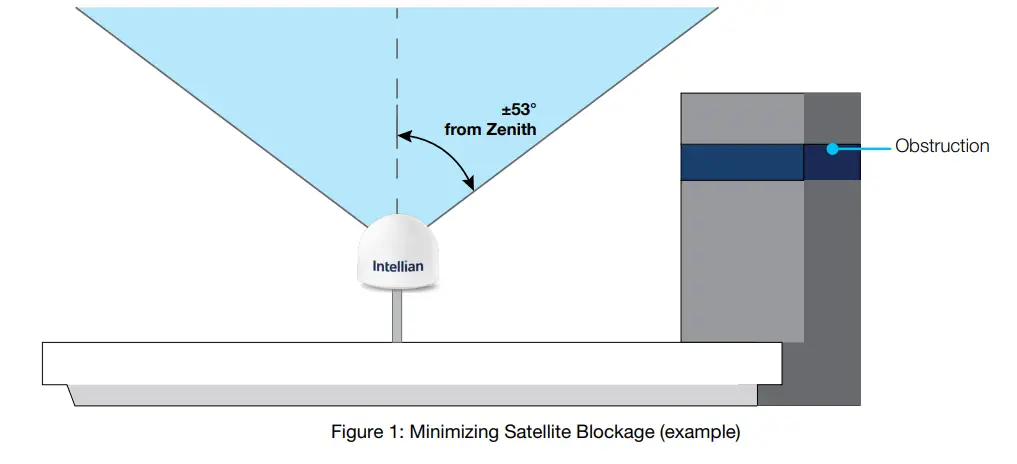
±53° from Zenith
Obstruction
Figure 1: Minimizing Satellite Blockage (example)
13
OW50SL-Dac – OneWeb LEO User Terminal
4.2.4 RF Hazard Precautions
The Federal Communications Commission has adopted a safety standard for human exposure to RF (Radio Frequency) energy, which is below the OSHA (Occupational Safety and Health Act) limits. To comply with current FCC RF Exposure limits, the antenna must be installed at or exceeding the minimum safe distance as guided by the antenna manufacturer or supplier.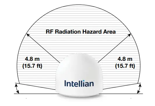
RF Radiation Hazard Area
4.8 m (15.7 ft)
4.8 m (15.7 ft)
NOTE This RF hazard is calculated using the following calculation.
· St: Power density in the transition region in in W/m2 · Pt: Power fed to the antenna feed horn in W · A: Physical (geometrical) area of the aperture antenna in m2 · Rnf: Extent of near-field in m · Rff: Distance to beginning of near field in m · R: Distance to the point of interest in m · D: Maximum dimension of antenna(Diameter if circular) in m · : Aperture efficiency (typically 0.5-0.75 for circular apertures) · : Wavelengths in m
14
4.3 System Package
Planning Installation
4.3.1 Outdoor Unit (ODU)
The OW50SL-Dac operates in a single parabolic basic configuration. The terminal consists of a pedestal, a reflector, RF modules and antenna control modules which are enclosed in a radome.
· Pedestal: Tilted 2-axial stabilized platform for the position compensation of the antenna
· RF modules: the antenna consists of a reflector, OMT, feeder and RCM which converts the satellite signals into the IF bands and up-converts IF bands to the forward-link satellite signals. The antenna includes the modem module, called SSM, which implements the necessary functionality to transmit and receive signals as well as communicate and command pointing directions to the antenna.
· Control modules: the antenna interface module, called AIM, controls the antenna motion by interfacing with the modem and RF modules.
· Radome: protects the antenna from outdoor environment.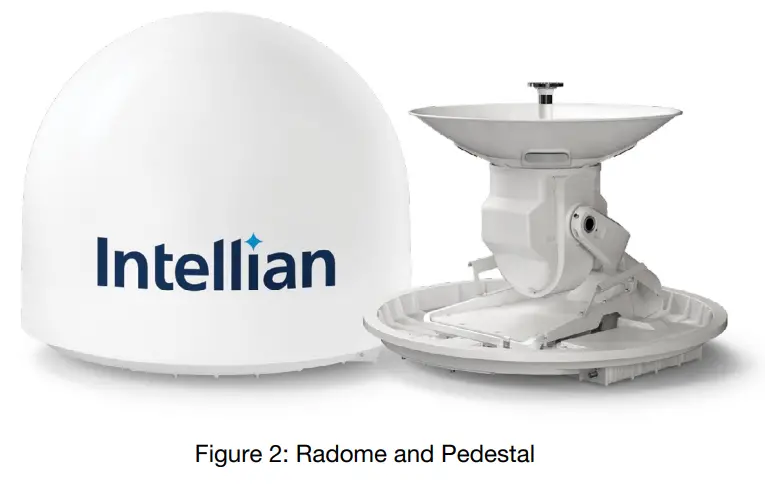
Figure 2: Radome and Pedestal
4.3.2 Customer Network Exchange (CNX)
The Customer Network Exchange (CNX) must be installed in a weather-protected area. It interfaces with user equipment and provides power and data interconnection to the outdoor unit. The CNX connects to the antenna while providing secure GigE connection to the Baseband Unit. The CNX takes 56 V input but can vary by product variant.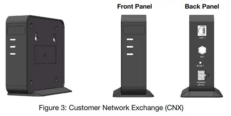
Front Panel
Back Panel
Figure 3: Customer Network Exchange (CNX)
15
OW50SL-Dac – OneWeb LEO User Terminal
4.3.3 Packing List
Before beginning installation, make sure you have all the included components. The User Terminal (UT) is composed of the following components.
OW50SL-Dac (without Heating Module)
Item
Q’ty Size
Description
OW50SL Antenna Unit
1
Single User Terminal
Quick Installation Guide (QIG)
1
Installation Manual
Customer Network Exchange (CNX) 1
114.2 mm x 125 mm x 35.2 mm
To access to OneWeb services
RG6 Coaxial Cable F(M) – F(M)
1
30 m
Coaxial Cable F(M)-F(M) for CNX Power & Data Connection
AC-DC Power Adaptor for CNX
1
To convert AC 100-240V Power to DC +56V Power for CNX (250W)
AC Power Cord (USA)
1
1.5 m
AC Power Cord (110 V)
AC Power Cord (CEEE7/7)
1
1.5 m
AC Power Cord (220 V)
Hex Bolt
4
M12 x 40L
Spring Washer
4
M12
Spare Bolt Kit for Mast Assembly
Flat Washer
4
M12
Hex-S Bolt SF
2
M5x8
Spare Grounding screw
RF Hazard Sticker
1
Radiation Safety Distance (10 m) Label
16
4.4 Installer/Customer Furnished Equipment
· Country specific power cable and socket for Power Adaptors · Grounding system that meets the local electrical code requirements · Waterproofing materials all connections · Tape or wraps to attach the antenna cable to the support structurer · Fasteners and other installation tools
Planning Installation
17
OW50SL-Dac – OneWeb LEO User Terminal
4.5 Unpacking System Package
Follow the steps for easy and safe unpacking.The system package consists of two sub-packages that an antenna package and an accessory package.
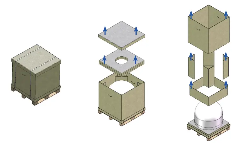
1. Place the package in a safe area large enough. Cut and remove the banding by using shears.
2. Open the package and remove 3. Remove the paper corner
the protective packing.
protectors and the box.
4. Take out the Antenna.
5. Remove the bottom cover and take out the items. · Refer to the Included items “4.3.3 Packing List” on page 16
NOTE · Make sure all the parts under the bottom cover (Step 5) are removed before the packaging is discarded. · Consider keeping the packaging material in case the terminal may need to be relocated in the future.
18
Installing Outdoor Unit ADU
Chapter 5. Installing Outdoor Unit (ODU)
5.1 General Requirements
5.1.1 Antenna Mounting Requirements
You need to procure or fabricate a suitable mounting plate and pole to support the ODU (Outdoor Unit). Consider the following factors to select the mounting method: · The physical size of the unit (632 mm (24.9 inches) high by 735 mm (28.9 inches) diameter). · The weight of the unit is About 23 kg (50.7 lbs). · The mechanical resonance of the system excited by wind : 5 Hz · Ensure the antenna is levelled ±2° in elevation and ±10° from the True North axis. · The mounting method should be able to preserve antenna pointing calibration under wind load and
protect safety of life and safety of property.
19
OW50SL-Dac – OneWeb LEO User Terminal
5.2 Antenna Dimensions
Before installing the antenna unit, confirm its height and diameter (see figure below). The mounting surface and overall space occupied by the radome must be sufficient for the height and diameter of the fully constructed radome on top of its mounting base.
Unit: mm (inches)
632 (24.9)
Ø735 (28.9)
Red Triangle (Align to the True North)
Mounting Hole Ø14 (0.55), 4 ea
247.5 (9.74)
Power & Data Housing
Ground ( EARTH )
M5 TAP
Power & Data Connector
247.5 (9.7) Figure 4: Antenna Dimension
20
Installing Above Deck Unit (ADU)
5.3 Measuring the North point
It needs to calibrate declination angle due to the difference between Magnetic North and True North. It is recommended to perform with antenna mounting at the same time.
A. When using a magnetic compass
1. Measure the orientation of the magnetic north by using a compass. 2. Mark the magnetic north point. 3. Get the magnetic declination angle at the installation area by the calculator (Refer to the Magnetic Field
Calculators on the National Oceanic and Atmospheric Administration (NOAA) website www.ngdc.noaa.gov). 4. Mark the True North point on the mounting plate by including the declination angle.
B. When using a GPS compass (To assist in better alignment of the User Terminal)
1. Check the orientation of the True North indicator. 2. Extending its virtual line from the centre of the User Terminal to the Tip of the True North indicator (Line)
by using your own GPS compass (Smart phone applications or devices). 3. Compare with virtual line and “Red triangle” on the bottom of radome to check any misalignment. Refer to the below App screen as a reference.
TRUE NORTH Current Location
Check the “True North”
Set your “Current Location”
Find the “True North” point
21
OW50SL-Dac – OneWeb LEO User Terminal C. When using a LUI 1. Connect an Ethernet cable from the LAN Port on the front panel of CNX to a LAN Port of PC. The Data
LED indicator will turn Green if CNX is connected. 2. Enter the IP address into your web browser’s address bar to log in to the Local User Interface (LUI).
· IP Address: 192.168.100.1 (Default) 3. Select the Antenna on the main menu then go to the Antenna Setup Heading menu. 4. For setting the true north offset, you need to select a satellite which is trackable in satellite information.
When the antenna tracks the selected satellite, true north offset can be calculated. · Heading(º): Enter the True north Offset Range (-180° ~ +180°). 5. Click the Submit button to apply the settings to the system.
1 2
3 4
Heading (º)
5
22
5.4 Designing Pole Mount
Installing Above Deck Unit (ADU)
5.4.1 Assembling Base Panel of NPM (Non-Penetrating Mount)
This is generally recommended. Check the requirement tools before assembling the NPM
FASTENERS
No
ITEM
DESCRIPTION
Q’ty
1
5/16″-18*3-1/8″ hex-head cap screw
4
TOOLS
2
5/16″-18*5/8″Round flat head Square screw 2
3
5/16″-18 washer
10
13 mm wrench
4
5/16″-18 nylon nut
6
5
Ø8.5/Ø12.5*L60 Bush
1
6
5/16″-18×1-1/4″ hex flange screw
1
7
5/16″-18 kepts k-lock nut
2
DESCRIPTION Ground Mounting Base(#A)
A
Q’ty
DESCRIPTION
1 Mast Pole(#B)
B
Q’ty
DESCRIPTION
Q’ty
1 Side Supporting Rods(#C)
4
C
1. Loosen the ground base 8 bolts.
Ground Mounting Base
Loose 4pcs screws for adjust mast pole width
Loose 4pcs screws for assemble side supporting rods
2. Assemble the mast pole with bolt kits.
Mast pole (2″ 50A Out diameter 60.5mm)
Grounding rod
3 1
5/16″-18*3-1/8″ Hex- head cap screw (1 ea)
5/16″-18 washer (2 ea), 5/16″-18 Nylon nut (1 ea)
4 3
Mast pole fix the lower square hole
23
OW50SL-Dac – OneWeb LEO User Terminal
3. Assemble 2 side supporting rods with bolt kits
3 1
4 3
Side supporting rod
4 3
5/16″-18*3-1/8″ Hex- head cap screw (3 ea)
5/16″-18 washer (5 ea), 5/16″-18 Nylon nut (3 ea) Bush (Ø8.5/Ø12.5*L60)
5 3
1
Adjust the width along with mast pole and side rods tighten 4 screws. – Suggest torque: 20 N-m – Max torque: 24 N-m
4. Assemble 2 side supporting rods with bolt kits
1
3
43
Side supporting rod
34
5/16″-18*3-1/8″ Hex- head cap screw (1 ea)
5/16″-18*5/18″ Round Flat head screw (2 ea)
5/16″-18 washer (4 ea), 5/16″-18 Nylon nut (3 ea)
2 43
2
Side supporting rod
Adjust the length along with side rods then tighten 4 screws. – Suggest torque: 20N-m – Max torque: 24 N-m
24
5. Assemble ground cable with bolt kits.
6 7
7
Penetrating fastener option: For directly mounting using fasteners, place appropriately fasteners, at the locations circled in the below diagram
Installing Above Deck Unit (ADU)
5/16″-18*1/1/4″ Hex- flange screw (1 ea),
5/16″-18 kepts k-lock, nut (2 ea)
Before assembly ground cable, tear off the grounding hole sticker (2 side).
8
12-3/4″ tapping screw (Optional)
8
25
OW50SL-Dac – OneWeb LEO User Terminal
5.4.2 Installing Customized Pole Mount
Customized pole mounts must be correctly installed to ensure a robust enough mount to prevent any flex, vibration, and sway when an external force is exerted on the installed antenna. A minimum of 3 fixtures must be used to assure mount strength. The figure to the right is an example of a proper customized pole mount installation.
Designing the Customized Pole Mount
When designing the pole mount, various pole types and their maximum length must be considered. The Fixture Distance describes the fixture attach points and the maximum distance between them. Refer to the following table for recommended specifications.
Pole Type
50A (Recommended)
65A 80A 90A
Pole Diameter
60.5 mm (2.4″) 76.3 mm(3.0″) 89.1 mm(3.5″) 101.6 mm(4.0″)
Pole Thickness
2 mm(0.1″) 2 mm(0.1″) 4 mm(0.2″) 4 mm(0.2″)
Max Length (A)
500 mm(19.7″)
650 mm(25.6″) 900 mm(35.4″) 1000 mm(39.4″)
Fixture Distance
400 mm(15.8″)
500 mm(19.7″) 700 mm(27.5″) 800 mm(31.5″)
Unit: mm (inches)
Max Length ( A )
A
The adjustable
A
antenna mount plate is
recommended.
B B
Fixture Distance
Fixture Distance
Recommended fixture type : U-bolt Clamp, Pipe Clamp
· As an example, if a 50A pole type is used for the antenna installation, the maximum length of cannot exceed 500mm. The remaining pole should be fixed with a minimum of 3 fixtures and the distance between them should be 400mm.
26
Installing Above Deck Unit (ADU)
· The Max Length of is the length between the top of the last fixture and the top of the mounting plate. To use the tilt adjustable mount plate, it is recommended pole type 50A be used. The recommended length for a 50A pole is 500 mm. If the pole type is different from the recommended types used refer to Table 1 above for recommended lengths.
· The sections of the pole have no length limits but must be installed with sufficient structural integrity to prevent any flex, vibration, and sway from wind or any other external forces. The pole sections can be used as a thicker pole type than the pole type, if needed. The attachment fixtures should be Installed at the recommended intervals (see the Fixture Distance in Table 1). The recommended fixture types are U-bolt clamps and a pipe clamps.
Mount Leveling The antenna should be mounted within +/- 2 ° elevation angle
within ±2°
Mount Plate
To more readily adjust the tilt level, it is recommended that the following Intellian adjustable mount plate is used (Refer to “5.5 Placing Antenna on Fine Tune assembly” on page 28.):
Intellian Part Number OW-NPM5-1075-ATP
Description NP Adjustable top plate (1EA)
Mounting Plate
1
TOP FINE TUNE ASSY.
NPM
5/16″-18*1″ Round flat head Square screw (4 ea)
5/16″-18 Flange nut (4 ea)
2
CLAMP ASSY.
27
OW50SL-Dac – OneWeb LEO User Terminal
5.5 Placing Antenna on Fine Tune assembly
5.5.1 Assembling the Fine Tune assembly
Check the requirement tools before assembling the Fine Tune assembly
FASTENERS
No
ITEM
DESCRIPTION
Q’ty
1
5/16″-18*1″ Round flat head Square screw
4
2
5/16″-18 Flange nut
4
3
M12*40 hex-head cap screw
4
4
M12 Spring Washer
4
5
M12 Washer
4
6
#12-3/4″ tapping screw
2
TOOLS 13 mm wrench 19 mm wrench
DESCRIPTION TOP FINE TUNE ASSY. (#A)
Q’ty
DESCRIPTION
1 CLAMP ASSY.(#B)
Q’ty
DESCRIPTION
Q’ty
1 BOTTOM PLATE CLAMP (#C)
4
DESCRIPTION
Q’ty
DESCRIPTION
Q’ty
TOP PLATE CLAMP (#D)
4 FIX CLAMP (#E)
4
Assemble top fine tune assembly and clamp assembly with bottom plate clamp using an adjustable Hex wrench.
Mounting Plate
1
TOP FINE TUNE ASSY.
NPM
5/16″-18*1″ Round flat head Square screw (4 ea)
5/16″-18 Flange nut (4 ea)
2
CLAMP ASSY.
28
5.5.2 Levelling the Mounting Plate
1. Put a Levelling tool on the centre of the mounting plate.
Installing Above Deck Unit (ADU)
Levelling tool
Mounting Plate
NPM
2. Rotate and adjust up & down the plates until they are perfectly parallel to the ground using the Levelling tool. Check to see whether the bubble is aligned with the guide circle.
Mounting Plate NPM
(Wrong)
(Correct)
29
OW50SL-Dac – OneWeb LEO User Terminal
5.6 Mounting Antenna on Mounting Plate
5.6.1 Moving Antenna Above the Mounting Plate
1. Lift the antenna above the plate and carefully lower down the antenna toward the NPM.
2. Align the end edge of the antenna foam with the end edge of the NPM plate. Make sure the antenna is centered with the the NPM plate when mounting the antenna on the NPM.
End Edge of the Antenna Foam End Edge of the NPM Plate
30
Installing Above Deck Unit (ADU)
5.6.2 Installing Bolts for Antenna-Mounting Plate Assembly
1. Locate the antenna mounting holes and roughly position the “Red triangle” on the radome towards *Magnetic North.
2. The circle markings in the figure indicate where the clamp positions would be installed. Insert the fix clamps between the antenna and NPM. Align the form corners on the antenna bottom with the fix clamps (4 ea). When these are aligned, the holes on the antenna foam and the holes on the clamp line up as well.
Foam corner
Fix clamp (4ea)
3. Find the M12x40L Hex. Bolt M12 Spring and Flat washer (4 ea) from the NPM Install Kit. Position the fixings & bolts into the antenna holes and do not fully tighten at this stage.
*This side down
DOWN
Fix Clamp
Top Plate 5 Clamp
4
3
M12x40L Hex. Bolt (4 ea)
M12 Spring washer (4 ea)
M12 washer (4 ea)
31
OW50SL-Dac – OneWeb LEO User Terminal
5.6.3 Aligning the Antenna to the True North
1. Confirm the red triangle on the bottom of the radome and rotate the antenna to align the middle strut of base.
Magnetic North
2. Mark the true north point on the mounting plate by including the declination angle using a True North indicator. (Refer to “5.6 Mounting Antenna on Mounting Plate” on page 30)
Align to the True North
True North
Fix the position and fully tighten the bolts after aligning
Magnetic North
3. Fix the position and fully tighten bolts after aligning the antenna.
WARNING · Ensure the antenna is mounted within ±2° elevation angle. · Ensure the antenna is aligned within ±10° degrees of True North.
within ±2°
True North 32
within ±10°
Installing Above Deck Unit (ADU)
5.6.4 Placing Concrete Blocks on Base Panels
1. Place the concrete blocks on the base panel to hold the weight of the antenna. One concrete block is 39 x 19 x 19 cm (15.3 x 7.5 x 7.5 inches) /17.56 kg (38.7 lbs). The area of the assembled base panel is 200 x 90 cm (78.7 x 35.4 inches).
2. Arrange 8 concrete blocks on the base panel in a single layer. The total weight of 9 concrete blocks is 158.0 kg (~ 348.3 lbs).
Concrete Blocks 3-Base Panels Figure 5: Placing Concrete Blocks on Base Panel of NPM NOTE If you want to use alternative weight instead of concrete blocks as shown above, please make sure that total weight of the alternative should meet suggested weight, 140.5 kg (~ 309.7 lbs).
33
OW50SL-Dac – OneWeb LEO User Terminal
5.7 Connecting Cable to Antenna
NOTE Make sure of the following before installing system cables. 1. All cables with connectors need to be fully secured and protected from physical damage. 2. Don’t acutely bend any cables during installation. 3. To reduce any damage from water (mist) or Ultraviolet Rays (UV), tape over using waterproof and UV
protective tape all the connectors located outside.
5.7.1 Connecting Cable to the Antenna Power & Data Connector
Terminate F(M) Connector on each end of RG6 (or RG11) Cable and Connect the F-Connector to the Power & Data connector on the antenna and CNX Unit.
Antenna
Power + Data RG6(or RG11) Coax Cable
Power & Data connector
CNX
RG6(or RG11) Coax Cable
Outdoor Units Indoor Units
SAT
Figure 6: Cable Connection of CNX to Antenna
NOTE · Choose RG6 or RG11 Coaxial Cable for or connecting the CNX depending on the cable length. The RG6
cable (30 m) is supplied to use to connect the CNX. If you use the RG11, separate purchase of RG11 cable should be needed. – RG6 (Supplied) : up to 30m (98.5 ft) – RG11 (Customer supplied): up to 100m (328 ft) · The RG6 cable for connecting the CNX are supplied in the accessory box. · To prevent cable damage, wrap the cable and connector by using a waterproof tape. (Refer to “11.5 Important Notice of Waterproofing Connector” on page 59.)
34
Installing Above Deck Unit (ADU)
5.8 Grounding Antenna
Direct grounding for the antenna is very important for safety. Your radio hardware must be protected from lightning strikes or static electricity by grounding. When establishing your grounding system, it must comply with the safety standards in your country. Ground the antenna in use separately.
M5 x 8 Hex. Bolt Figure 7: Grounding Antenna
35
Installing Indoor Unit IDU
OW50SL-Dac – OneWeb LEO User Terminal
Chapter 6. Installing Indoor Unit (IDU)
6.1 CNX Dimensions
Confirm the dimensions of the CNX before installing it.
125 (4.9)
Unit: mm (inches)
35.2 (1.4)
114.2 (4.5)
Figure 8: CNX Dimensions CAUTION · This equipment design typically applies to commercial or industrial equipment expected to be installed
in locations where only adults are normally present. · This product is intended to be supplied from Intellian by a Listed Power Adaptor, rated 56 V DC, 4.48 A
minimum, if need further assistance, please contact OneWeb for further information. · Ensure to connect the power cord to a socket-outlet with earthing connection. · Never open the equipment. For safety reasons, the equipment should be opened only to qualified
service personnel. This appliance classification of use by a Skilled person.
36
Installing Below Deck Unit (BDU)
6.2 Antenna System Configuration
For the proper operation of your satellite communication system, it must be connected with all the provided components as shown in the figures below. The basic antenna system consists of the antenna and CNX. The Antenna Includes the SSM Module, which is capable of controlling and managing the antenna systems simultaneously.
Antenna
Includes SSM Module
Outdoor Units Indoor Units
RG6(or RG11) Coax Cable: Power + Data
CNX
Power Adapter (AC-DC) 250 W
Figure 9: Antenna System Configuration of OW50SL-Dac (Standard)
NOTE
· Choose RG6 or RG11 Coaxial Cable for or connecting the CNX depending on the cable length. The RG6 cable (30 m) is supplied to use to connect the CNX. If you use the RG11, separate purchase of RG11 cable should be needed. – RG6 (Supplied) : up to 30m (98.5 ft) – RG11 (Customer supplied): up to 100m (328 ft)
· The RG6 cable for connecting the CNX are supplied in the accessory box.
37
OW50SL-Dac – OneWeb LEO User Terminal
6.3 CNX Cable Connection
6.3.1 CNX Back Panel Connectors
The following figure shows the CNX back panel connectors.
CNX
LAN (CAT5) Coax (RG6 or RG11) Reset Power
Figure 10: Back Panel Connectors
6.3.2 CNX Connector Pinout Guide
Reference the following connector pinout information for the connection Ports of the CNX.
LAN Connector
12345678
RJ-45 Female
Pin 1 BI_DA+ 2 BI_DA3 BI_DB+ 4 BI_DC5 BI_DC+ 6 BI_DB7 BI_DD+ 8 BI_DD-
Signal
38
Coax Connectors Power Connector
Installing Below Deck Unit (BDU)
RF F Type Female
Conductor Inner Outer
Function Power + Data GND
14 25 36
6 Contact Power Plug Male
Pin 1 2 3 4 5 6
Return GND Return +56V DC NC +56V DC
Signal
39
Documents / Resources
 |
Intellian OW50SL-Dac OneWeb LEO User Terminal [pdf] User Guide OW50SL-Dac OneWeb LEO User Terminal, OW50SL-Dac, OneWeb LEO User Terminal, LEO User Terminal, User Terminal |