Intellian Technologies OW50SL-Dac OneWeb LEO User Terminal User Manual

Chapter 7. Operating CNX
CNX Front Panel View
Check the connection status with the LED indicators on the front panel of CNX.
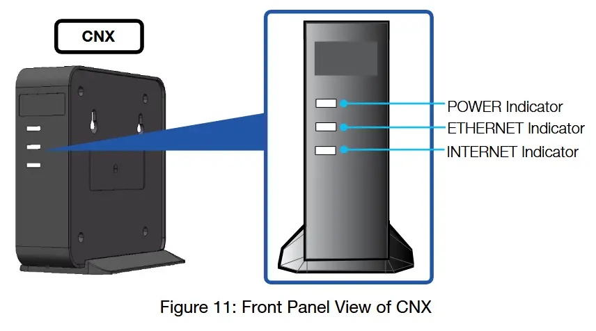
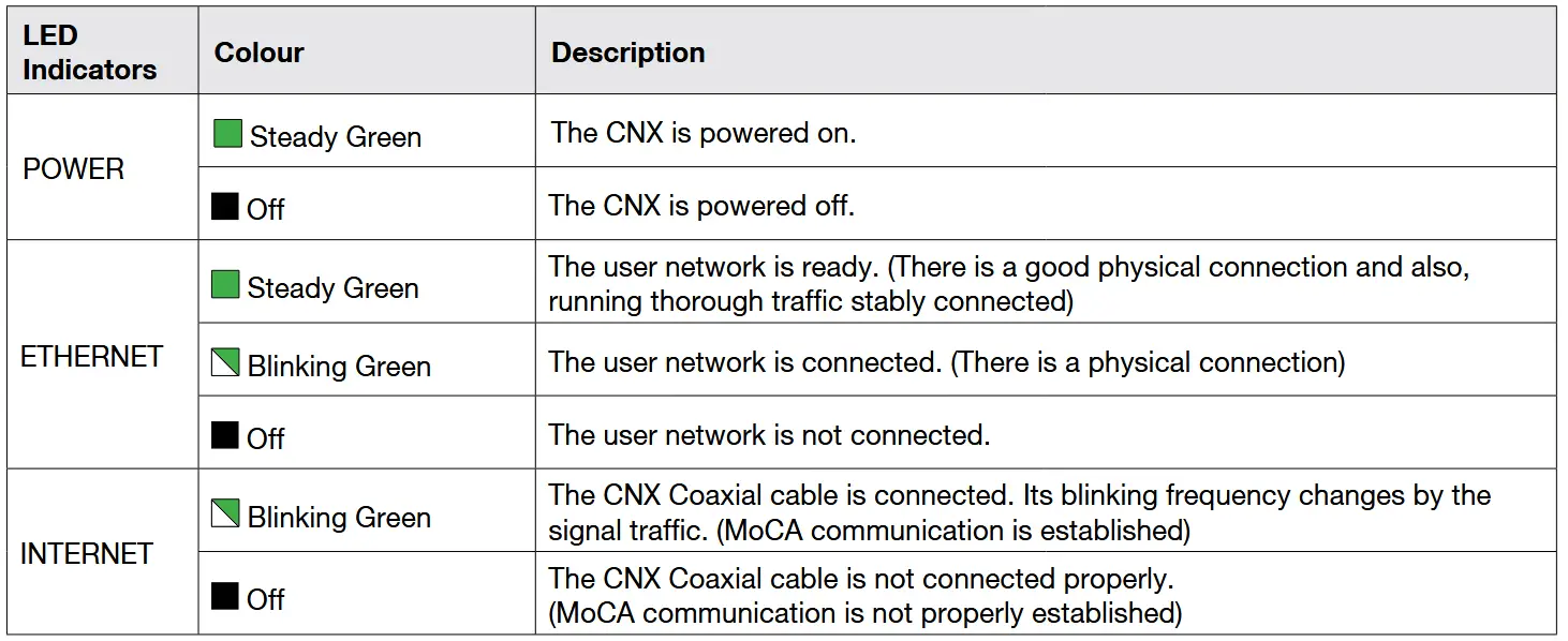
The following table shows status indicators on the CNX.
Chapter 8. Using Local User Interface (LUI)
Introduction
With the embedded Using Local User Interface (LUI) software, the antenna can be monitored, controlled, and diagnosed remotely through a web browser. It saves your time and cost generated by various maintenance activities such as operating firmware upgrades, tracking parameter resets, and system diagnosis, etc.
Requirements to Access OneWeb Web Interface
The LUI can be accessible by Chrome web browser.
![]() NOTE
NOTE
LUI works on Chrome web browsers. (Intellian recommended using Chrome web browser when operating LUI.)
Turning On System
The antenna has to be connected to the CNX and powered up in order to access the webpage.
The CNX should be connected to a power adapter before connecting between the antenna and CNX.
Accessing Webpage
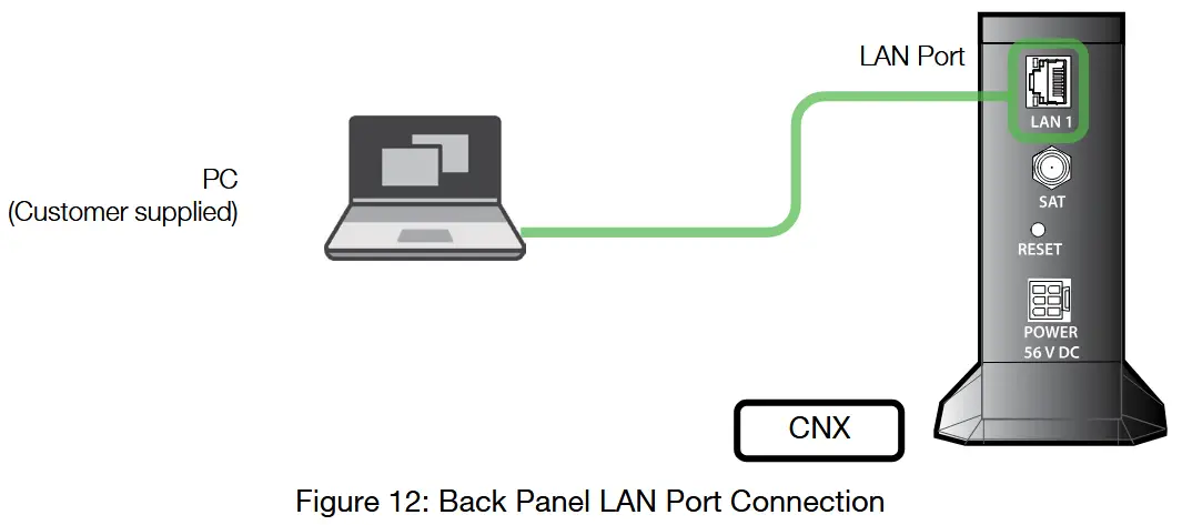
TCP/IP Connection through LAN Port
The network is automatically configured by DHCP with no additional PC IP configuration.
- Connect an Ethernet cable from the LAN Port on the front panel of CNX to a LAN Port of PC. The Data LED indicator will turn Green if CNX is connected.
- Enter the IP address into your web browser’s address bar to log in to the Local User Interface (LUI).
• IP Address: 192.168.100.1 (Default)
Webpage Layout
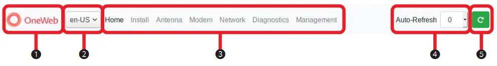
Once you log in, the following information and menus are displayed.
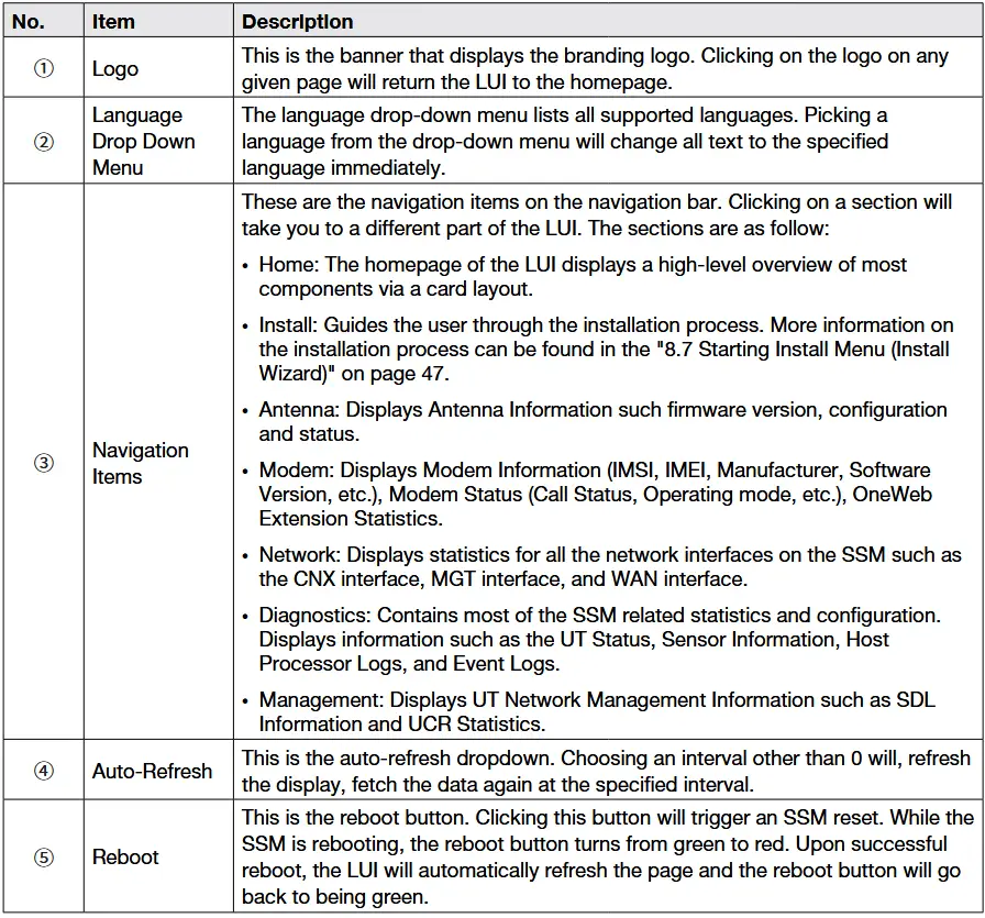
The navigation bar as shown below is the primary way being able to navigate the LUI. The navigation bar is persistent across all LUI pages.
Home Page
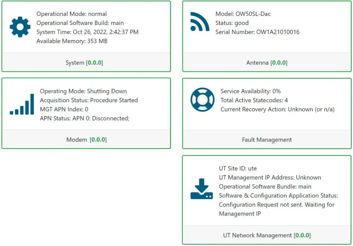
The home page consists of several cards that display a high-level overview of certain components such as the UT System, Antenna, or UT Network Management. Each card has a border that, depending on the status of the subsystem, changes colour. If the subsystem is in a bad state, the card is outlined in red. If the subsystem is behaving as normal, then the card is outlined in green. Clicking on a card will take you to the webpage where you can find more detailed information about the subsystem.
The footer, like the navigation bar, is persistent throughout all LUI pages. The footer contains two pieces of information: one on the left and one on the right.
The current software version that is running on the Host Processor is displayed on the left. The operational software mode follows the software version. If the operational software mode is a factory, the text colour is red. If the operational software mode is main, the text colour is green. Clicking on this will take you to the UT Status section of the Diagnostics page.
The system uptime is displayed on the right. It displays how much time has passed since the last reboot. The format is days:hours:minutes:seconds.
![]()
Setting Up Cable and Antenna
This section describes how to setup the antenna.
Setting up the antenna is required before “7.7 Starting Install Menu (Install Wizard)”.

RF Cable Setup
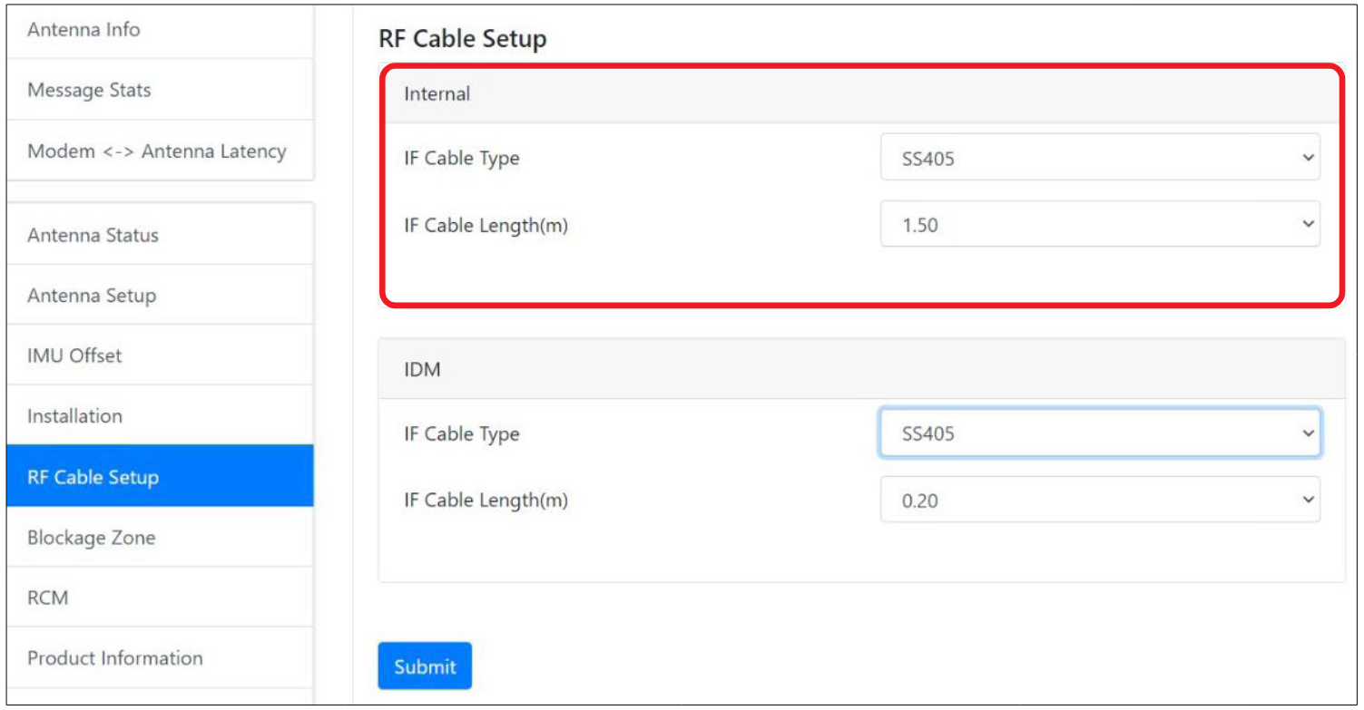
The IF Cable Type and IF Cable Length(m) on the Internal is pre-set with a default value depending on the RF cable. Make sure that is the same with the following default values.
- IF Cable type : SS405
- IF Cable Length(m) : 1.50
TILT Calibration
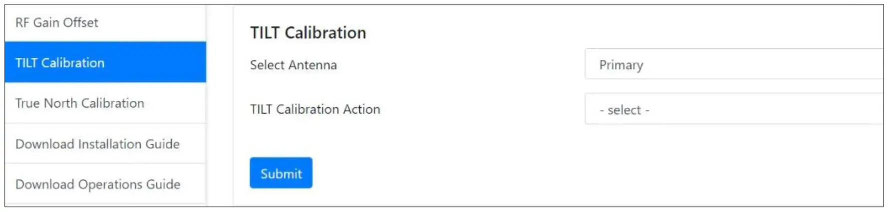
The Tilt Calibration must be applied t the antenna. Choose the Primary on the Select Antenna and select the Start Calibration on the TILT Calibration Action from the drop-down list. If you select the Stop on the TILT Calibration Action and Click the Submit, the antenna system will stop the tilt calibration.
Click on Submit, then click on Next. The antenna system will start the tilt calibration.
Antenna Setup
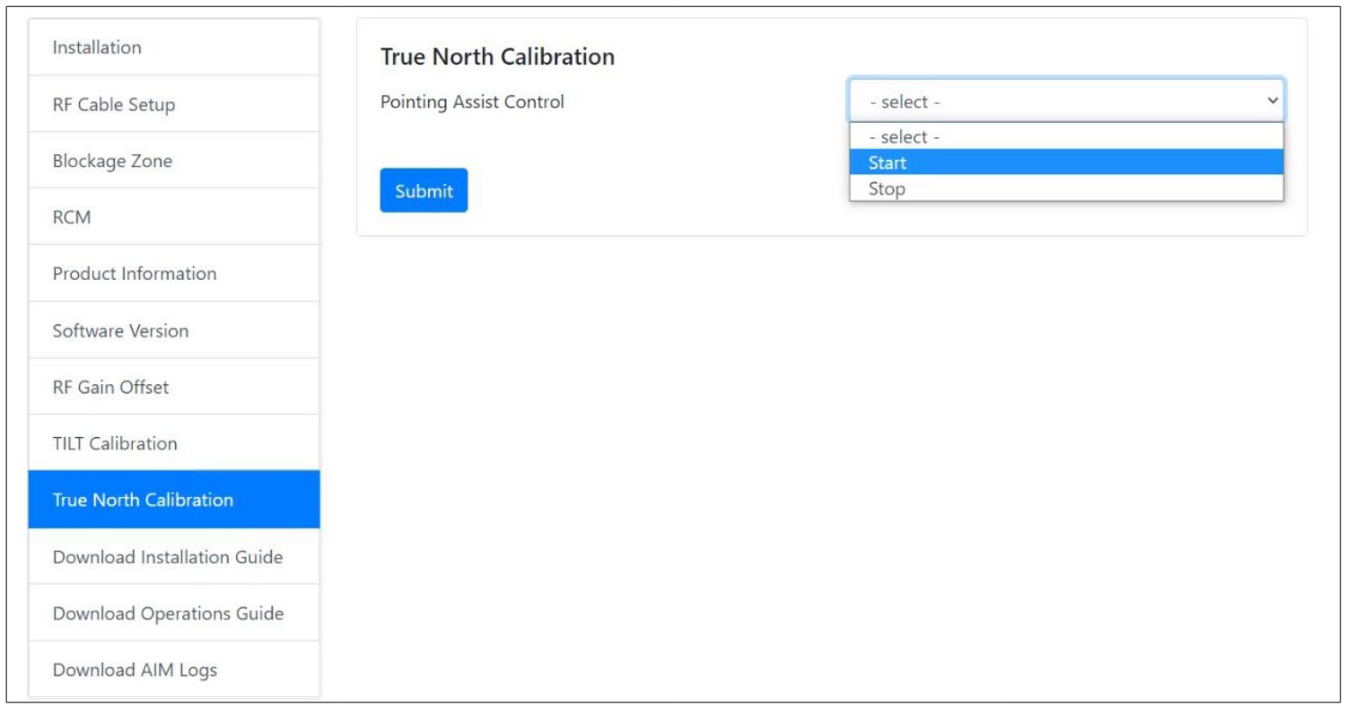
This section can be skipped if this is first time setting up the antenna. Only if the antenna is moved to a different location, select Start for Auto Pointing Assistant and click on Submit.
The Install Wizard will give you a guide by going through the steps of setup for the antenna system commissioning. We highly recommend using this wizard to complete your installation and commissioning of the system. After accessing LUI main page, go to the Install menu on the navigation bar and perform the wizard.

The LUI Installation page serves as the front end for installation.

On the right are three buttons:
- Start Over button: Brings you back to the first step of the installation.
- Back button: Steps one step back in the installation.
- Next button: Advances to the next step in the installation.
If a given state is required, the Next button is disabled, and the installation cannot proceed until the current step has been completed.
Initial Install Page
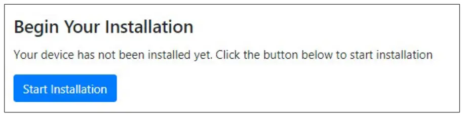
The first page of the installation process is a splash screen that states that the UT has not yet been installed. To proceed with the installation to the next step, click on Start Installation or Next.
Upload Software Bundle
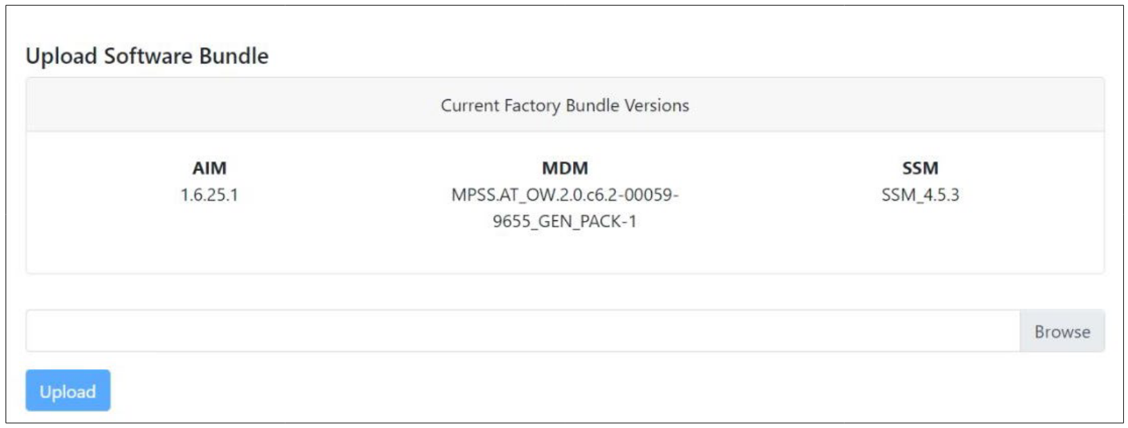
The Upload Software Bundle page displays the current software versions running on each component. Clicking on the empty text box or the Browse button allows the upload of a Software Bundle. Until a bundle has been uploaded, the Upload button is greyed out. If the upload is not successful, a status error message will be displayed.
New Software Listing
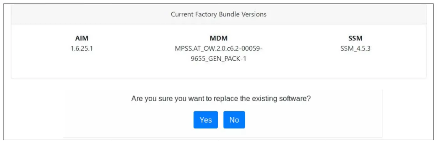
Upon a successful upload, the New Software version is displayed beneath the current software along with a prompt. Clicking No. It deletes the bundle file that was uploaded and returns you back to the beginning of the state in which you must upload another bundle file. Clicking Yes then triggers the next step of this state which is performing the updates. If an update fails for any given component, an error message is displayed and the SSM stops attempting to update the rest of the components. Upon a successful update, the SSM will reset itself and the LUI will refresh the page once the SSM has finished rebooting. After the reboot, you can click to advance to the next state.
Upload Ephemeris Data
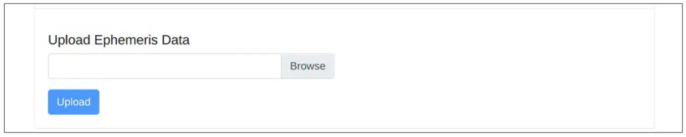
The Upload Ephemeris Data page is a simple file upload page. Simply click on the empty text box or the Browse button to upload an Ephemeris file. Until a file has been uploaded, the upload button is greyed out. Upon a successful upload, a success status message will be displayed, and the state can be advanced. Click on Next.
![]() NOTE
NOTE
What is Ephemeris Data?
Ephemeris Data contains current information about the orbits of the satellites in the OneWeb constellation. The User Terminal uses ephemeris data to determine the positions of the satellites in the sky at any given time.
Remark: Every 30days, this data file is updated. Once User Terminal is commissioned this will be updated automatically.
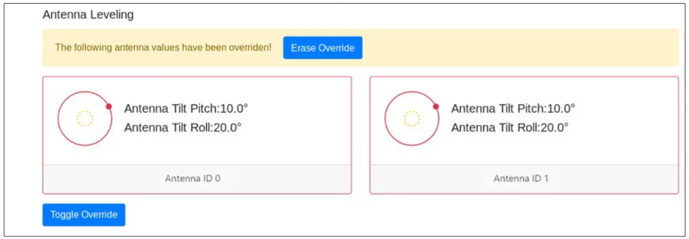
Antenna Levelling

The antenna Levelling page displays the current sensor data received from the antenna.
The “Tilt Pitch: degrees” and “Tilt Roll: degrees” are displayed. If the degree values meet the tolerance, the card for the corresponding antenna is outlined in Green; otherwise, it is outlined in Red.
If it is Red, antennal Levelling has to be re-done until the display becomes Green. When Levelling is re-done, “7.6.2 TILT Calibration” has to be done after the installation completes. If the installation fails, it could be due to the incorrect Levelling; therefore, installation has to be re-done.
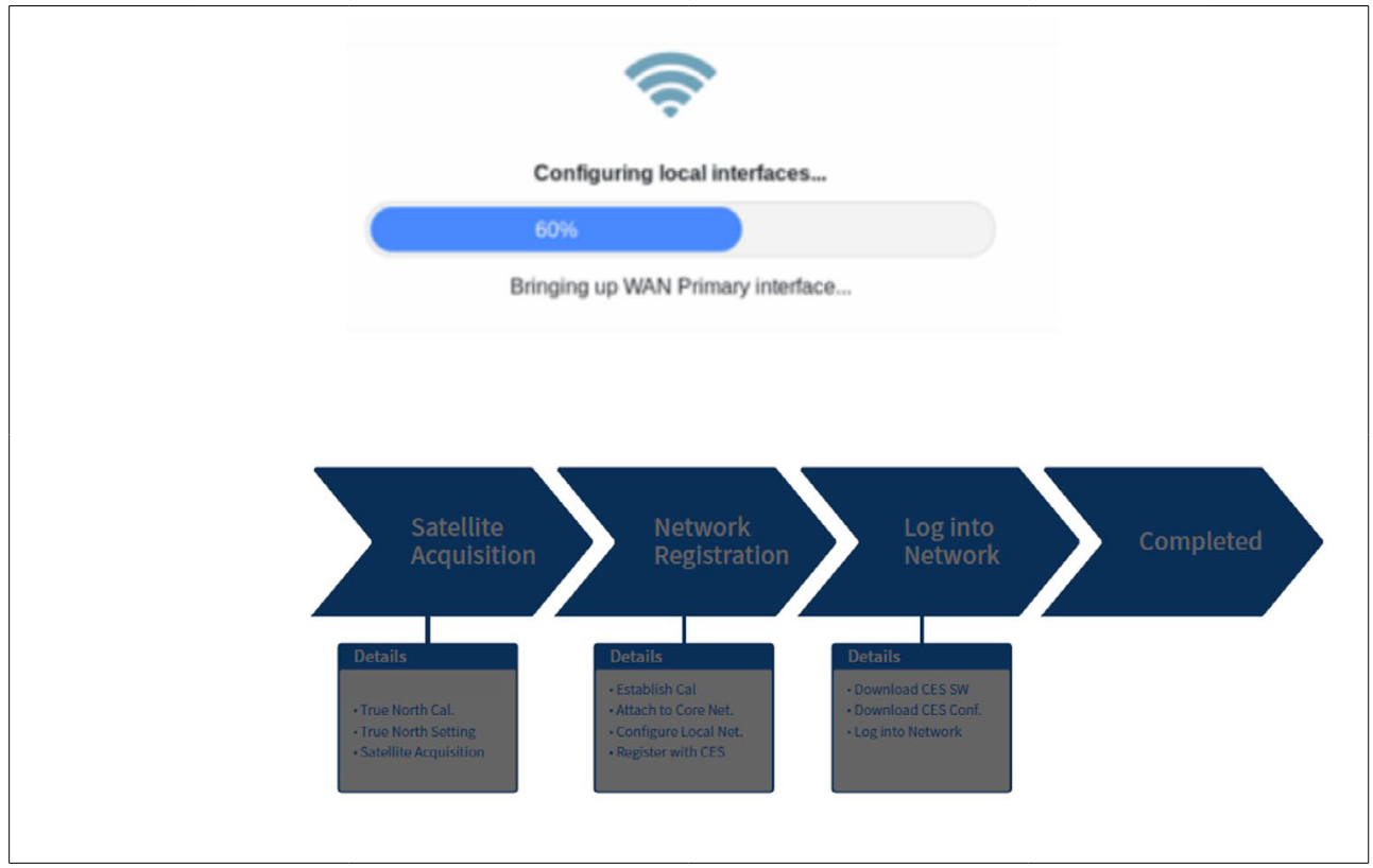
Autonomous States
Autonomous states all display a progress bar of its progress. The following states require no action from the user aside from proceeding to the next state. All installation states are displayed, or some installation status is displayed underneath the progress bar.
Chapter 9. Specification
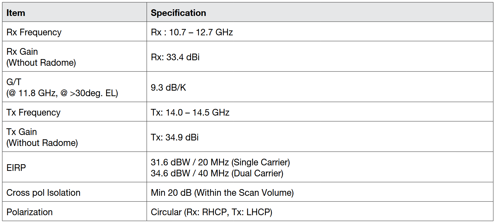
Technical Specification
RF Specification
System Specification
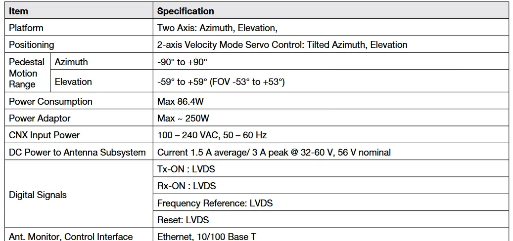
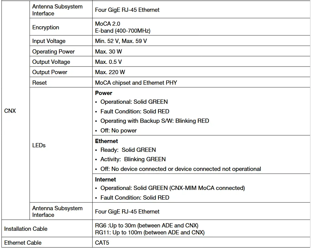
Mechanical & Power Specification

※ Package size may change with design revisions
Environmental Specification
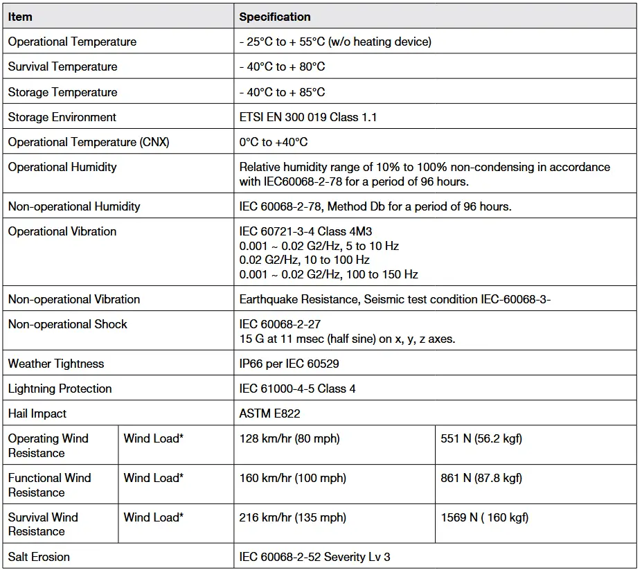
* Wind Load: N is weight expression unit: newton and kgf is 9.80665N
Chapter 10. Warranty
Subject to the terms and conditions set forth in this Intellian Standard Global Warranty, the Agreement and/or any other terms and conditions agreed upon by Distribution partners and Intellian, Intellian satellite antenna products are warranted against defects in parts and workmanship for a period of one (1) year in respect of defects in parts and for a period of one (1) year in respect of the factory labor.
Warranty Time Period: Warranty periods commence from the date of shipment from an Intellian facility.
If installation occurs within six months of the date of shipment from an Intellian facility then Intellian will extend the duration of the warranty by the number of days between shipment and installation of the terminal. If installation occurs on or after six months of the date of shipment then the duration of the warranty will not be extended.
This Warranty shall be void for any Product which has been subjected to “Intellian Standard Global Warranty”.
Warranty Claim Procedure: Information on Intellian’s warranty policy and coverage can be found on the Intellian Partner Portal. Intellian’s warranty policy aims to reimburse Distribution partners for a reasonable percentage of costs and time that would be incurred when repairing an Intellian system. Intellian’s warranty policy does not cover any other costs including those incurred by Distribution partners to support End Users.
To submit a Warranty Claim with Intellian. Please follow the directions in “Intellian Standard Global Warranty”.
Chapter 11. Appendix
Pre-Installation Checklist
This pre-installation checklist describes important considerations before installing the UT. It must be completed by the certified installer to install in a safe location. Please fill out the general information below.
Date of Survey:
Date of Install (If different from installation date):
Installer Information
- Company Name:
- Installer’s Name:
- Contact Phone Number:
- Address:
- Email:
Customer Information
- Organization Name:
- Customer Name:
- Phone Number:
- Address:
- Email:
- Site Location (Lat / Long.):
- UT Type Being Installed (w. CNX):
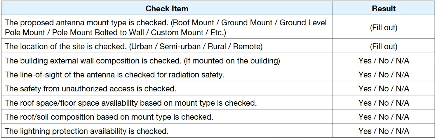
The following checklist is to be completed by the Installer.
Building / Site checklist
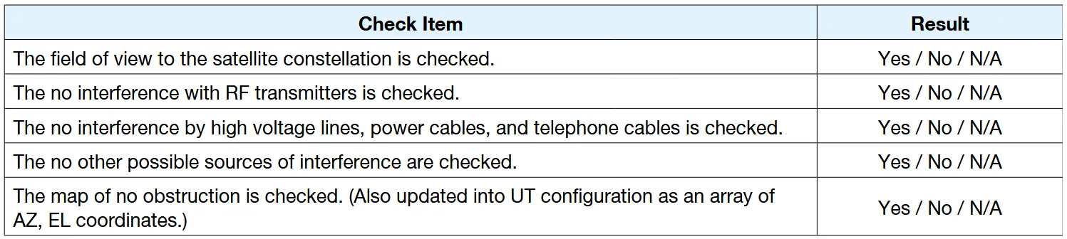
Expected Obstructions / Possible Interference checklist
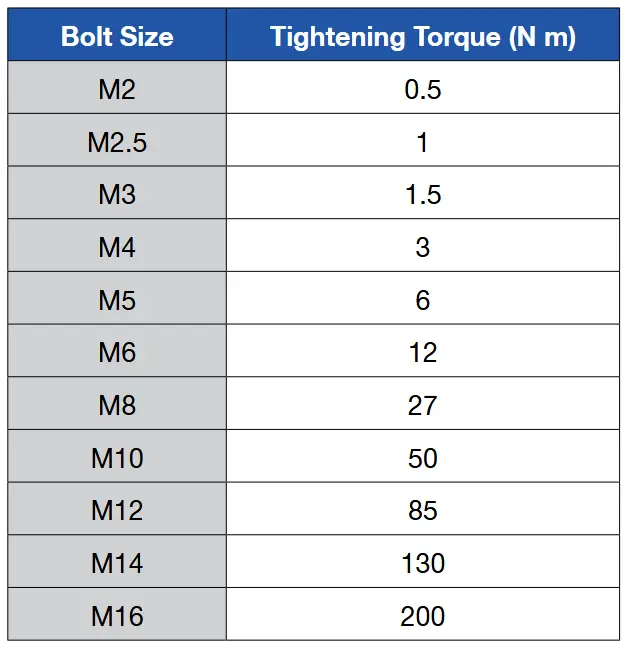
Tightening Torque Specification
This table shows the recommended values of tightening torques.
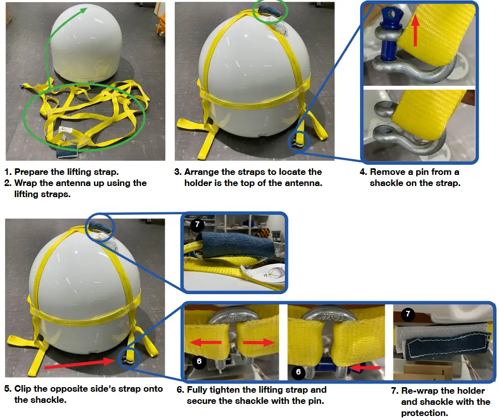
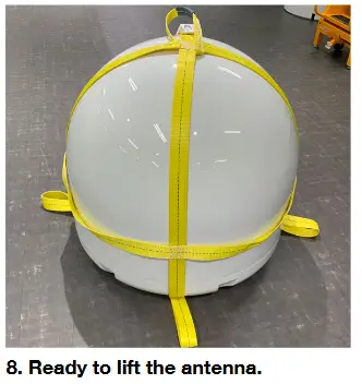
Using a lifting strap
When you install the antenna unit to the mounting plate (or other surfaces), you can use the lifting strap. To use the lifting strap, Refer to pictures below. (A separate purchase of the lifting strap is required.)
Make sure that before installing the lifting strap on the antenna, has plenty of room.
Checking separately sold items
Refer to separately sold items list below table.
Accessory Kit

Accessories

Important Notice of Waterproofing Connector
Introduction
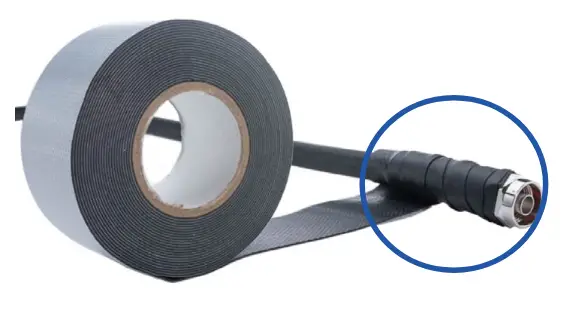
During antenna installation, it is important to ensure that once the cable is connected to the antenna, proper waterproofing of the connector must b e done with a self-amalgamating tape.
If you need any assistance, please contact Intellian Technical Support (support@intelliantech.com).
Outline of Taping
Self-amalgamating tape comes with a protective, plastic peel-away layer that allows the tape to rolled and shipped. To waterproof a connector, you need to begin by peeling away a portion of this protective plastic layer and then start wrapping the tape around it.
Procedure
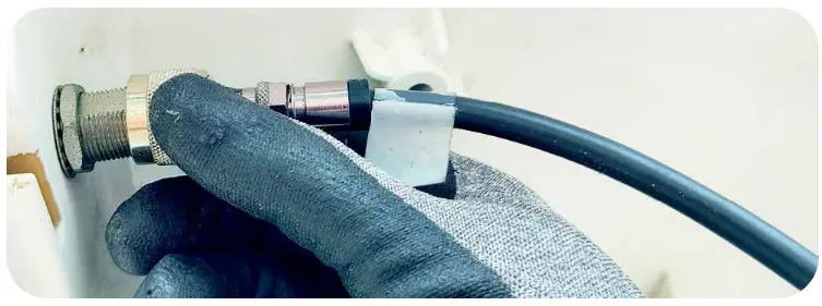
- Connect the cable to the connector to be fully secured.
 CAUTION
• DO NOT over-tighten the connector, nuts, or screws when mounting the antenna to prevent any damage.
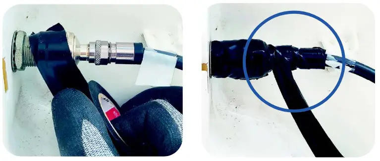
• DO NOT leave any cables loosen and non-fixed, especially for those installed outside of the antenna. - Apply tape over the connector.
It is important to wrap the cable onto itself and the best practice is to wrap the tape over itself by 50%, meaning that once you wrap your first layer your second layer should overlap over half of the first layer, and so on. This ensures that you get a strong bond between the different layers of tape that properly adhere to one another.
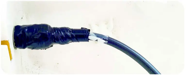
- Ensure that the entire RF connector is taped up as shown the picture right.
 WARNING
• Note that you cannot use ordinary electrical tape to waterproof the RF connector. Only self-amalgamating tape is able to waterproof the connector properly.
• Failure to do so will result in rust and corrosion to the cable and its connector and this might end up damaging the antenna.
Documents / Resources
 |
Intellian Technologies OW50SL-Dac OneWeb LEO User Terminal [pdf] User Manual OW50SL-Dac, OW50SL-Dac OneWeb LEO User Terminal, OW50SL-Dac, OneWeb LEO User Terminal, User Terminal, Terminal |