
Inovonics EN1941 Family One-Way Binary RF Module Instruction Manual

1 Overview
EchoStream RF modules are designed to be easily interfaced with your electronic remote application controller (RAC), allowing the assimilation of any user-specific application into an EchoStream system. Once integrated with existing products, RF modules provide you with complete EchoStream functionality.
One-way binary RF modules are end-devices that use a logic-level connection to interface with your RAC.

Note: For UL 2560 installations, refer to the EN6080 Area Control Gateway
Installation Instructions or EN6040-T Network Coordinator Installation Instructions.
1.1 Maximum Number of Repeaters for a UL 2560 Installation
To achieve the 99.99% alarm message reliability required for UL 2560 compliance, system installations must operate within the following limits for end device and repeater counts.

1.2 Inovonics Wireless Contact Information

If you have any problems with this procedure, contact Inovonics Wireless technical services:
- E-mail: support@inovonics.com.
- Phone: 800-782-2709; 303-939-9336.
1.3 Installation Notes
- These products are designed to be installed and maintained by professional security technicians.
- Products are intended for indoor use.
- Manually test all products weekly.
2 One-Way Binary RF Module Components
The EN1941 is a universal one-way binary RF module with two alarm input pins, allowing the use of dual inputs. Input one is the primary alarm, bit 0; input two is the secondary alarm, bit 1.

N/O selection pins Place a jumper to select normally open inputs; remove the jumper to select normally closed.
Note: The EN1941 is shipped with the jumper unattached. With the jumper unattached, the EN1941 defaults to normally closed.
Frequency band selection pins Place a jumper on the left two pins, marked NZ, to set the frequency range to 921-928 MHz for New Zealand; place a jumper on the bottom two pins, marked AU, to set the frequency range to 915-928 MHz for Australia.
Note: The EN1941 is shipped with the jumper unattached. With the jumper unattached, the EN1941 defaults to 902-928 MHz for use in North America.
Secondary alarm Connects a secondary end-device to provide RF alarm data for any user-specific application.
Primary alarm Connects a primary end-device to provide RF alarm data for any user-specific application.
Tamper input Connects a tamper input to send a message when userspecific end-device is tampered with.
Reset input Connects a reset input to reset the one-way binary RF module after a frequency band selection change or N/O – N/C selection change, and to initiate an RF transmission.
Power Connect power cabling to an external power supply of 2.6 to 5.5 volts.
Ground Connects to ground.
Mounting hole Used to mount the one-way binary RF module to the userspecific product. The mounting hole should only be used with a nylon standoff, never metal.
LED contacts Use to control an LED switch. Not designed to drive LED power.
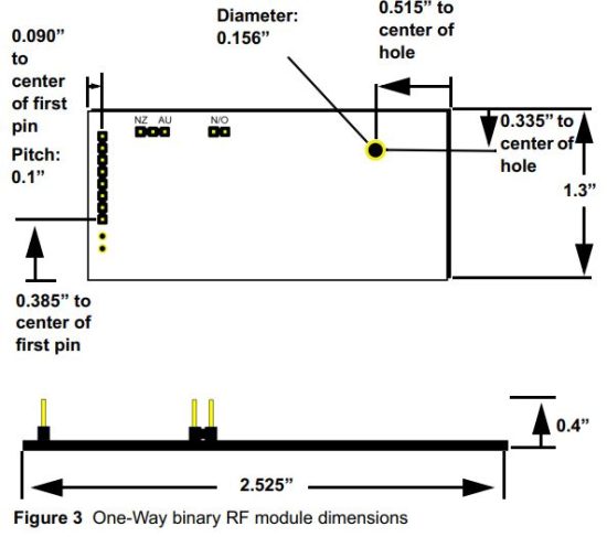
3 One-Way Binary RF Module Dimensions
4 One-Way Binary RF Module Connections and Output Jumpers

5 Installation Notes
- One-way binary RF modules are designed to be easily interfaced with your electronic remote application controller, however integration must conform to the following:
- The RF module must only be connected at the eight pin header or eight pin plated through-holes.
- All cables and wires must be routed away from the component side of the RF module.
- The integrated antenna must not be tampered with; no connection to an alternate antenna is provided.
- The application module must not include an integrated secondary colocated radio module.
- The one-way binary RF module antenna should be placed so that it is facing away, or otherwise isolated from, your device’s ground plane.
- Components that are sensitive to RF transmission, such as high gain circuits, should be isolated from the antenna to prevent interference.
- One-way binary RF modules should not be mounted on metal surfaces or inside metal enclosures. They should also not be mounted where sheet metal ductwork, wire mesh screens, etc. might block transmissions.
6 One-Way Binary RF Module Requirements
6.1 Power Requirements
The one-way binary RF module has an on-board voltage regulator.
Connect power cabling to an external power supply (Vcc) of 2.6 to 5.5 volts. Voltage must be sustained at 2.6 volts or above and supply 100 milliamps during the transmit cycle.

Note: For UL 2560 installations, transmitters must have a minimum checkin time of 60 minutes.
6.2 Low Battery Condition
The one-way binary RF module measures battery voltage every three and a half hours, and, when the battery measures 2.6 volts, a serial message is sent indicating a low battery condition.
6.3 Temperature range
-20°C to +60°C, non-condensing
6.4 RF network compatibility
EchoStream commercial mesh network.
6.5 Input Requirements
Caution: Input levels must not exceed 3.3 V.
Open When an active source (open collector or dry contact) is used to drive the alarm or tamper input, the voltage should be between 0.75xVcc and Vcc. A passive input should have an impedance of greater than 5.1k ohm between the input and ground.
Closed When an active source is used, the voltage should be less than 0.25xVcc. A passive input should have an impedance of less than 240 ohm.
6.6 LED Requirements
The LED output is an active output from the microprocessor, with a 1k series resistor to limit current draw. Default state is low, and the LED pin is pulled high during transmit.
7 Compliance Requirements
7.1 UL and cUL Requirements
The module holds a UL and cUL Recognized Component Mark and is intended to be factory installed in another device, system or end-product.
The suitability of the module for use in a UL and/or cUL listed (certified) device, system or end-product, is restricted as follows:
- The EN1941 was evaluated as a UL/cUL Recognized Component compliant to UL 2610, UL 639, ULC-S306 and ULC/ORD-C1076 as specified in the Conditions of Acceptability of the UL Report.
- The Supply Line Transient tests shall be added to the RAC UL evaluation program if it is powered by an AC/DC adapter rather than a low voltage battery.
- If intended use includes UL2610, UL639 installations, the RAC shall be evaluated for Short Range RF Device tests.
- Compatible UL receivers (except for UL 2560) include EN4216MR, EN4232MR and EN7285. Refer to the EN4216MR Installation and Operation Manual, the EN4232MR Installation and Operation Manual or the EN7285 Installation Instructions.
- The EN1941-60 is a UL2560 unlisted component.
- The compatible receivers for UL 2560 installations are the EN6080 area control gateway and EN6040-T network coordinator. Refer to the EN6080 Area Control Gateway Installation Instructions and the EN6080 Area Control Gateway User Manual, or the EN6040-T Network Coordinator Installation Instructions.
- The compatible repeater for UL 2560 installations is the EN5040-20T.
- When selecting frequency band, only devices set for use in North America are configured for UL and cUL installations.
- In a UL 2560 installation, the EN1941-60 one-way binary RF module may be used with completed emergency call systems for assisted living and independent living facilities
- For UL 2560 certified system installations, the following Inovonics EchoStream devices are approved for installation within maximum system configuration limits defined in section 1.1 of this document:
– EN6080 area control gateway or EN6040-T network coordinator.
– EN5040-20T high power repeater.
– End devices (transmitters) with a minimum 60-minute check-in interval, as follows:
Fundamental devices which are subject to UL2560 certification (pendant transmitters and OEM products using the Inovonics RF module)
Supplemental devices which are not subject to UL2560 system certification but which may be used within a UL2560 certified system (e.g. universal transmitters and activity sensors) - Users that have achieved certification and will install UL 2560 certified systems are responsible for labeling all fundamental devices with the UL 2560 system certification mark.
- Transmission requirements must be checked for any integration, and integrators are responsible for ensuring compliance with KDB 996369 D04. Please refer to the EN1941/EN1941-60/EN1941XS Installer Manual for more details.
7.2 FCC Requirements for the RF Module
The one-way binary RF module has received a Modular Grant to FCC/IC regulations. The integrator is responsible to test the final installation to verify compliance to FCC/IC regulation for unintentional emissions.
Changes or modifications not expressly approved by the party responsible for compliance could void the user’s authority to operate the equipment.
The integrator is responsible for properly labeling the product containing the one-way binary RF module. Labels must be placed on the outside of the product, and must include a statement indicating that the product contains the module, along with the FCC and IC number.
8 Television and Radio Interference
This equipment has been tested and found to comply with the limits for a Class B digital device, pursuant to Part 15 of the FCC Rules. These limits are designed to provide reasonable protection against harmful interference in a residential installation. This equipment generates, uses and can radiate radio frequency energy and, if not installed and used in accordance with the instructions, may cause harmful interference to radio communications. However, there is no guarantee that interference will not occur in a particular installation. If this equipment does cause harmful interference to radio or television reception, which can be determined by turning the equipment off and on, the user is encouraged to try to correct the interference by one or more of the following measures:
- Reorient or relocate the receiving antenna.
- Increase the separation between the equipment and receiver.
- Connect the equipment into an outlet on a circuit different from that to which the receiver is connected.
- Consult the dealer or an experienced radio/TV technician for help.
9 FCC Part 15 and Innovation, Science and Economic Development Canada (ISED) Compliance
This device complies with part 15 of the FCC Rules, and ISED licenseexempt RSS standard(s). Operation is subject to the following two conditions: (1) this device may not cause interference, and (2) this device must accept any interference that may cause undesired operation of the device.
Note: Changes or modifications not expressly approved by the party responsible for compliance could void the user’s authority to operate the equipment.
10 Radiation Exposure Limits
10.1 FCC
This equipment complies with FCC radiation exposure limits set forth for an uncontrolled environment. In order to avoid the possibility of exceeding the FCC radio frequency exposure limits, human proximity to the antenna shall not be less than 20 cm during normal operation. Co-location of this module with other transmitters that operate simultaneously are required to be evaluated using the FCC multi-transmitter procedures..
10.2 ISED
This equipment complies with ISED RSS-102 radiation exposure limits set forth for an uncontrolled environment. This transmitter must be installed to provide a separation distance of at least 20 cm from all persons and must not be co-located or operating in conjunction with any other antenna or transmitter.
Note: Inovonics commercializes products utilizing open source third party software. For additional information, please visit: https://www.inovonics.com/support/embedded-third-party-licenses/.
Note: Inovonics supports recycling and reuse whenever possible. Please recycle these parts using a certified electronics recycler. Inovonics supports recycling and reuse whenever possible. Please recycle these parts using a certified electronics recycler.
6.19.25 357-00087-01 Rev A © Inovonics, 2025 – www.inovonics.com
Read More About This Manual & Download PDF:
Documents / Resources
 |
Inovonics EN1941 Family One-Way Binary RF Module [pdf] Instruction Manual EN1941-60, EN1941 Family One-Way Binary RF Module, EN1941, Family One-Way Binary RF Module, One-Way Binary RF Module, Binary RF Module, RF Module, Module |