![]()
S6SATU01A I2C Interface for PMIC Communication Tool
Please note that Cypress is an Infineon Technologies Company.
The document following this cover page is marked as “Cypress” document as this is the company that originally developed the product. Please note that Infineon will continue to offer the product to new and existing customers as part of the Infineon product portfolio.
Continuity of document content
The fact that Infineon offers the following product as part of the Infineon product portfolio does not lead to any changes to this document. Future revisions will occur when appropriate, and any changes will be set out on the document history page.
Continuity of ordering part numbers
Infineon continues to support existing part numbers. Please continue to use the ordering part numbers listed in the datasheet for ordering.
THIS SPEC IS OBSOLETE
Spec No: 002-08680
Spec Title: S6SATU01A I2C INTERFACE FOR PMIC
COMMUNICATION TOOL OPERATION GUIDE
Replaced by: NONE
© Cypress Semiconductor Corporation, 2014-2022. This document is the property of Cypress Semiconductor Corporation and its subsidiaries, including Spansion LLC (“Cypress”). This document, including any software or firmware included or referenced in this document (“Software”), is owned by Cypress under the intellectual property laws and treaties of the United States and other countries worldwide. Cypress reserves all rights under such laws and treaties and does not, except as specifically stated in this paragraph, grant any license under its patents, copyrights, trademarks, or other intellectual property rights. If the Software is not accompanied by a license agreement and you do not otherwise have a written agreement with Cypress governing the use of the Software, then Cypress hereby grants you a personal, nonexclusive, nontransferable license (without the right to sublicense) (1) under its copyright rights in the Software (a) for Software provided in source code form, to modify and reproduce the Software solely for use with Cypress hardware products, only internally within your organization, and (b) to distribute the Software in binary code form externally to end users (either directly or indirectly through resellers and distributors), solely for use on Cypress hardware product units, and (2) under those claims of Cypress’s patents that are infringed by the Software (as provided by Cypress, unmodified) to make, use, distribute, and import the Software solely for use with Cypress hardware products. Any other use, reproduction, modification, translation, or compilation of the Software is prohibited.
TO THE EXTENT PERMITTED BY APPLICABLE LAW, CYPRESS MAKES NO WARRANTY OF ANY KIND, EXPRESS OR IMPLIED, WITH REGARD TO THIS DOCUMENT OR ANY SOFTWARE OR ACCOMPANYING HARDWARE, INCLUDING, BUT NOT LIMITED TO, THE IMPLIED WARRANTIES OF MERCHANTABILITY AND FITNESS FOR A PARTICULAR PURPOSE. To the extent permitted by applicable law, Cypress reserves the right to make changes to this document without further notice. Cypre does not assume any liability arising out of the application or use of any product or circuit described in this document. Any information provided in this document, including any sample design information or programming code, is provided only for reference purposes. It is the responsibility of the user of this document to properly design, program, and test the functionality and safety of any application made of this information and any resulting product. Cypress products are not designed, intended, or authorized for use as critical components in systems designed or intended for the operation of weapons, weapons systems, nuclear installations, life-support devices or systems, other medical devices or systems (including resuscitation equipment and surgical implants), pollution control or hazardous substances management, or other uses where the failure of the device or system could cause personal injury, death, or property damage (“Unintended Uses”). A critical component is any component of a device or system whose failure to perform can be reasonably expected to cause the failure of the device or system, or to affect its safety or effectiveness. Cypress is not liable, in whole or in part, and you shall and hereby do release Cypress from any claim, damage, or other liability arising from or related to all Unintended Uses of Cypress products. You shall indemnify and hold Cypress harmless from and against all claims, costs, damages, and other liabilities, including claims for personal injury or death, arising from or related to any Unintended Uses of Cypress products.
Cypress, the Cypress logo, Spansion, the Spansion logo, and combinations thereof, WICED, PSoC, CapSense, EZ-USB, F-RAM, and Traveo are trademarks or registered trademarks of Cypress in the United States and other countries. For a more complete list of Cypress trademarks, visit cypress.com. Other names and brands may be claimed as property of the
Preface
This manual explains how to use the evaluation board. Be sure to read this manual before using the product.
For this product, please consult with sales representatives or support representatives.
Handling and use
Handling and use of this product and notes regarding its safe use are described in the manuals.
Follow the instructions in the manuals to use this product.
Keep this manual at hand so that you can refer to it anytime during use of this product.
Notice on this document
All information included in this document is current as of the date it is issued. Such information is subject to change without any prior notice.
Please confirm the latest relevant information with the sales representatives.
Cautions
Caution of the products described in this document
The following precautions apply to the product described in this manual.
| Indicates a potentially hazardous situation which could result in death or serious injury and/or a fault in the user’s system if the product is not used correctly. |
| Electric shock, Damage |
Before performing any operation described in this manual, turn off all the power supplies to the system. Performing such an operation with the power on may cause an electric shock or device fault. |
| Electric shock, Damage |
Once the product has been turned on, do not touch any metal part of it. Doing so may cause an electric shock or device fault. |
| Indicates the presence of a hazard that may cause a minor or moderate injury, damages to this product or devices connected to it, or may cause to lose software resources and other properties such as data, if the device is not used appropriately. |
| Cuts, Damage | Before moving the product, be sure to turn off all the power supplies and unplug the cables. Watch your step when carrying the product. Do not use the product in an unstable location such as a place exposed to strong vibration or a sloping surface. Doing so may cause the product to fall, resulting in an injury or fault. |
| Cuts | The product contains sharp edges that are left unavoidably exposed, such as jumper plugs. Handle the product with due care not to get injured with such pointed parts. |
| Damage | Do not place anything on the product or expose the product to physical shocks. Do not carry the product after the power has been turned on. Doing so may cause a malfunction due to overloading or shock. |
| Damage | Since the product contains many electronic components, keep it away from direct sunlight, high temperature, and high humidity to prevent condensation. Do not use or store the product where it is exposed to much dust or a strong magnetic or electric field for an extended period of time. Inappropriate operating or storage environments may cause a fault. |
| Damage | Use the product within the ranges given in the specifications. Operation over the specified ranges may cause a fault. |
| Damage | To prevent electrostatic breakdown, do not let your finger or other object come into contact with the metal parts of any of the connectors. Before handling the product, touch a metal object (such as a door knob) to discharge any static electricity from your body. |
Description
The S6SATU01A is communication tool for 2ch Buck + 1ch Buck/Boost DC/DC, S6SAP412A and for 3ch Buck + 1ch Buck/Boost DC/DC, S6SAP413A. This board implements our MCU : FM3(MB9AF312K) and can communicate with I2 C easily by using windows PC and prepared software. It can select the output voltage, soft-start time, ON/OFF sequence, PFM/PWM mode.

Pin Descriptions
2.1 Input/output pin descriptions
Table 2-1. Input/output Pin Descriptions
| Block | Pin symbol | I/O | Function description |
|
MCU |
GND | – | Ground terminal |
| VBUS | O | VBUS terminal | |
| USB_VCC | I | USB_VCC terminal | |
| I2CVCC | I | Power supply terminal for I2C. | |
| SCL_S | I | I2C clock terminal | |
| SDA_S | I/O | I2C data I/O terminal | |
| P10 | I/O | MCU I/O port (25pin) | |
| JP110 | – | GND through JP110 | |
| P11 | I/O | MCU I/O port (26pin) | |
| JP111 | – | GND through JP111 | |
| P12 | I/O | MCU I/O port (27pin) | |
| JP112 | – | GND through JP112 | |
| P13 | I/O | MCU I/O port (28pin) | |
| JP114 | – | GND through JP114 | |
| P14 | I/O | MCU I/O port (29pin) | |
| P15 | I/O | MCU I/O port (30pin) | |
| JP115 | – | GND through JP115 | |
| P21 | I/O | MCU I/O port (36pin) | |
| P22 | I/O | MCU I/O port (35pin) | |
| P23 | I/O | MCU I/O port (34pin) |
2.2 Jumper, Switch descriptions
Figure 2-1. Jumper, Switch Descriptions
| Jumper, Switch | Description | Initial setting |
| JP101 | Short CN103 (2pin) and MCU I/O port (4pin) | Solder Short |
| JP102 | Short CN103 (3pin) and MCU I/O port (3pin) | Solder Short |
| JP104 | Short VBUS and VCC | Solder Short |
| JP105 | Short VCC and I2CVCC | Solder Short |
| JP108 back side | Short MCU I/O port (31pin) and (32pin) | Pattern Short |
| JP110 back side | Short CN104 (8pin) and GND | Pattern Short |
| JP111 back side | Short CN104 (10pin) and GND | Pattern Short |
| JP112 back side | Short CN104 (12pin) and GND | Pattern Short |
| JP114 back side | Short CN104 (14pin) and GND | Pattern Short |
| JP115 back side | Short CN104(17pin) and GND | Pattern Short |
| JP116 back side | Short CN105(5pin) and GND | Pattern Short |
| JP117 back side | Short CN105(13pin) and GND | Pattern Short |
| JP131 back side | Short MCU MD0 pin (21pin) and VCC | Open |
| JP132 back side | Short CN105(14pin) and MCU I/O port (15pin) | Solder Short |
| JP133 back side | Short CN105(15pin) and MCU I/O port (16pin) | Solder Short |
| SW101 | Reset push switch for MCU | – |
| CN101 | USB connector | – |
| CN102 | Test terminal | – |
| CN103 | Test terminal | – |
| CN104 | 1,8,10,12,14,17 : GND pin 2 : VBUS pin 3 :USB_VCC pin 4 :I2CVCC pin 5 : SCL_S pin 6 : SDA_S pin 7 : P10 pin 9 : MCU P11 pin 11 : MCU P12 pin 13 : MCU P13 pin 15 : MCU P14 pin 16 : MCU P15 pin 18 : MCU P21 pin 19 : MCU P22 pin 20 : MCU P23 pin |
– |
| CN105 | Test terminal | – |
Setup and Verification
3.1 Contents in a Package
| No. | Contents | Description | Quantity | Notes |
| 1 | S6SATU01A | I2C Communication board | 1 | – |
| 2 | USB cable | USB to USB mini B cable | 1 | – |
| 3 | L-Angle connector | Connector for PMIC board | 1 | – |

- S6SATU01A
- USB cable
- PC installed Windows7 or later OS
- S6SAP412A or S6SAP413A
3.2 Evaluation with I2 C control
Any setting of S6SAP412A/S6SAP413A can be evaluated with Windows PC connected to USB port by I2 C communication GUI.

3.2.1 PC Setup
- Unpack the driver file to a folder of PC running Windows 7 or later version OS, and run install.bat file.
- Connect S6SATU01A to PC using USB cable.
- After installed a device, open the device manager and confirm the new COM port.
Start menu → Control panel → Device manager
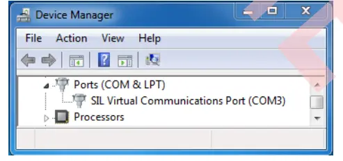
- Run “S6AP412A_413A_I2C.exe”
- Click “PORT SEARCH” at “COM PORT SELECT” field and select “SIL Virtual Communications Port (COMxx) ”

- Please unplug the USB cable after setup.
3.2.2 Operation check
- Connect the S6SATU01A and S6SAP412A/S6SAP413A.
- 3.3V is applied to VIN terminal of S6SAP412A/S6SAP413A.
- USB cable is connected.
- Run I2 C communication software and click the box of ON/OFF field.

- Vo1, Vo2, Vo3 or Vo4 are output by software settings Figure 3-1. For I2C control evaluation

3.2.3 How to use I2 C communication GUI


Component and Wiring Layout
4.1 Component layout
Figure 4-1. Component Layout (Layer 1) 
Figure 4-2. Component Layout (Layer 2)

4.2 Wiring layout
Figure 4-3. Wiring Layout (Layer 1) 
Figure 4-4. Wiring Layout (Layer 2)

Circuit Schematic
Figure 5-1. Circuit Schematic

Component List
Table 6-1. Component List
| No. | Component | Item | Parts number | Vendor | Value |
Remarks |
| 1 | IC101 | MCU | MB9AF312K | Cypress | – | – |
| 2 | IC102 | – | – | – | – | NMT |
| 3 | IC103 | PMIC | TCR5SB33 | TOSHIBA | – | – |
| 4 | IC104 | – | – | – | – | NMT |
| 5 | Q101 | Tr | BC857BLT1G | ROHM | – | PNP |
| 6 | X101 | – | – | – | – | NMT |
| 7 | X102 | Crystal | CX1255GB04000 H0PESZ1 | KYOCERA | 4MHz | – |
| 8 | LED101 | LED | OSHR1608C1A | OptoSupply | – | RED |
| 9 | SW101 | Push-SW | SKHRAHA010 | ALPS | – | – |
| 10 | C101 | Ceramic Capacitor | C1608JB1H106M | TDK | 10µF | 50V |
| 11 | C109 | Ceramic Capacitor | C1608JB1H106M | TDK | 10µF | 50V |
| 12 | C110 | Ceramic Capacitor | C1608JB1H106M | TDK | 10µF | 50V |
| 13 | C102 | – | – | – | – | NMT |
| 14 | C104 | – | – | – | – | NMT |
| 15 | C105 | – | – | – | – | NMT |
| 16 | C107 | Ceramic Capacitor | C1608JB1V475K | TDK | 4.7µF | 35V |
| 17 | C103 | Ceramic Capacitor | C1608JB1H104K | TDK |
0.1µF |
50V |
| 18 | C105 | – | – | – | – | NMT |
| 19 | C106 | Ceramic Capacitor | C1608JB1H104K | TDK | 0.1µF | 50V |
| 20 | C108 | Ceramic Capacitor | C1608JB1H104K | TDK | 0.1µF | 50V |
| 21 | C111 | Ceramic Capacitor | C1608JB1H104K | TDK | 0.1µF | 50V |
| 22 | C114 | Ceramic Capacitor | C1608JB1H104K | TDK | 0.1µF | 50V |
| 23 | C115 | – | – | – | – | NMT |
| 24 | C116 | Ceramic Capacitor | C1608JB1H104K | TDK | 0.1µF | 50V |
| 25 | C120 | Ceramic Capacitor | C1608JB1H104K | TDK | 0.1µF | 50V |
| 26 | C112 | Ceramic Capacitor | C1608C0G1H12 0J |
TDK |
12pF | 50V |
| 27 | C113 | Ceramic Capacitor | C1608C0G1H12 0J |
TDK |
12pF | 50V |
| 28 | C118 | – | – | – | – | NMT |
| 29 | C119 | – | – | – | – | NMT |
| 30 | R137 | Chip Resistor | RK73H1JTTD4R 70F | KOA | 4.7Ω | |
| 31 | R106 | Chip Resistor | RR0816P-152-D | SUSUMU | 1.5kΩ | |
| 32 | R108 | – | – | – | – | NMT |
| 33 | R109 | – | – | – | – | NMT |
| 34 | R110 | – | – | – | – | NMT |
| 35 | R117 | – | – | – | – | NMT |
| 36 | R113 | Chip Resistor | RR0816P-563-D | SUSUMU | 56kΩ | |
| 37 | R138 | Chip Resistor | RR0816P-102-D | SUSUMU | 1kΩ | |
| 38 | R111 | Chip Resistor | RR0816P-103-D | SUSUMU | 10kΩ | 1/16W, 0.5% |
| 39 | R112 | Chip Resistor | RR0816P-103-D | SUSUMU | 10kΩ | 1/16W, 0.5% |
| 40 | R101 | Chip Resistor | RR0816P-103-D | SUSUMU | 10kΩ | 1/16W, 0.5% |
| 41 | R104 | Chip Resistor | RR0816P-103-D | SUSUMU | 10kΩ | 1/16W, 0.5% |
| 42 | R114 | – | – | – | – | NMT |
| 43 | R115 | – | – | – | – | NMT |
| 44 | R116 | – | – | – | – | NMT |
| 45 | R123 | Chip Resistor | RR0816P-202-D | SUSUMU | 2kΩ | 1/16W, 0.5% |
| 46 | R124 | Chip Resistor | RR0816P-202-D | SUSUMU | 2kΩ | 1/16W, 0.5% |
| 47 | R125 | Chip Resistor | RR0816P-202-D | SUSUMU | 2kΩ | 1/16W, 0.5% |
| 48 | R126 | Chip Resistor | RR0816P-103-D | SUSUMU | 10kΩ | 1/16W, 0.5% |
| 49 | R127 | – | – | – | – | NMT |
| 50 | R128 | – | – | – | – | NMT |
| 51 | R129 | – | – | – | – | NMT |
| 52 | R130 | Chip Resistor | RR0816P-103-D | SUSUMU | 10kΩ | 1/16W, 0.5% |
| 53 | R131 | Chip Resistor | RR0816P102D | SUSUMU | 1kΩ | 1/16W, 0.5% |
| 54 | R132 | Chip Resistor | RR0816P-103-D | SUSUMU | 10kΩ | 1/16W, 0.5% |
| 55 | R133 | Chip Resistor | RR0816P-220-D | SUSUMU | 22Ω | 1/16W, 0.5% |
| 56 | R134 | Chip Resistor | RR0816P-220-D | SUSUMU | 22Ω | 1/16W, 0.5% |
| 57 | R135 | – | – | – | – | NMT |
| 58 | R136 | Chip Resistor | RR0816P-103-D | SUSUMU | 10kΩ | 1/16W, 0.5% |
| 59 | R137 | – | – | – | – | NMT |
| 60 | R138 | – | – | – | – | NMT |
| 61 | R139 | Chip Resistor | RR0816P-103-D | SUSUMU | 10kΩ | 1/16W, 0.5% |
| 62 | R140 | Chip Resistor | RR0816P-103-D | SUSUMU | 10kΩ | 1/16W, 0.5% |
| 63 | R141 | Chip Resistor | RR0816P-103-D | SUSUMU | 10kΩ | 1/16W, 0.5% |
| 64 | R102 | Chip Resistor | RR0816P-202-D | SUSUMU | 2kΩ | 1/16W, 0.5% |
| 65 | R103 | – | – | – | – | NMT |
| 66 | R105 | Chip Resistor | RR0816P-222-D | SUSUMU | 2.2kΩ | 1/16W, 0.5% |
| 67 | R118 | – | – | – | – | NMT |
| 68 | R119 | – | – | – | – | NMT |
| 69 | R120 | – | – | – | – | NMT |
| 70 | R121 | – | – | – | – | NMT |
| 71 | R122 | – | – | – | – | NMT |
| 72 | CN101 | Connector | UX60SC-MB-5ST | HIROSE | – | mini USB |
| 73 | CN102 | – | – | – | – | NMT |
| 74 | CN103 | – | – | – | – | NMT |
| 75 | CN104 | Connector | 90122-0770 | MOLEX | – | 2×10 L-angle pin header |
|
76 |
CN105 |
Connector |
90122-0770 |
MOLEX |
– |
2×10 L-angle pin header, Cut 90122-0770 |
| 77 | JP110 | JMP | JPPAD | – | – | Pattern Short |
| 78 | JP111 | JMP | JPPAD | – | – | Pattern Short |
| 79 | JP112 | JMP | JPPAD | – | – | Pattern Short |
| 80 | JP114 | JMP | JPPAD | – | – | Pattern Short |
| 81 | JP115 | JMP | JPPAD | – | – | Pattern Short |
| 82 | JP116 | JMP | JPPAD | – | – | Pattern Short |
| 83 | JP117 | JMP | JPPAD | – | – | Pattern Short |
| 84 | JP101 | Solder JMP | JPPAD | – | – | Solder Short |
| 85 | JP102 | Solder JMP | JPPAD | – | – | Solder Short |
| 86 | JP108 | JMP | JPPAD | – | – | Pattern Short |
| 87 | JP131 | – | – | – | – | NMT |
| 88 | JP132 | JMP | JPPAD | – | – | Pattern Short |
| 89 | JP133 | JMP | JPPAD | – | – | Pattern Short |
| 90 | JP104 | Solder JMP | JPPAD | – | – | Solder Short |
| 91 | JP105 | Solder JMP | JPPAD | – | – | Solder Short |
Evaluation Board Picture
Figure 7-1. Picture (top)

Figure 7-2. Picture (back)

Ordering Information
Table 8-1. Ordering Information
| Part number | EVB revision | Note |
| S6SATU01A00SU1101 | Rev 1.0 | — |
Revision History
Document Revision History
Document Title: S6SATU01A I2 C Interface for PMIC Communication Tool Operation Guide
Document Number: 002-08680
| Revision | Issue Date | Origin of Change |
Description of Change |
| ** | 7/22/2014 | MITK | Initial release. |
| *A | 2/4/2016 | MITK | Migrated Spansion Guide from S6SATUO1A_SS901-00027-1v0-E to Cypress format. |
| *13 | 11/30/2017 | MASG | Updated Cypress new logo and copyright. |
| *C | 8/22/2022 | ATTS | Obsolete document. Completing Sunset Review. |
![]() S6SATU01A I2 C Interface for PMIC Communication Tool Operation Guide, Doc. No. 002-08680 Rev. *C
S6SATU01A I2 C Interface for PMIC Communication Tool Operation Guide, Doc. No. 002-08680 Rev. *C
Documents / Resources
 |
infineon S6SATU01A I2C Interface for PMIC Communication Tool [pdf] Installation Guide S6SATU01A I2C Interface for PMIC Communication Tool, S6SATU01A, I2C Interface for PMIC Communication Tool, PMIC Communication Tool, Communication Tool |