IMSA VMPS Technical Eligibility Form Appendix

Product Information
Specifications
- Engine Power Table
- Sensors
- VMPS
- VMPS Antenna
- X2 Transponder
- Fuel Flow Meter
- Leader Light System
- XAP NTX Marshalling Display
- Accident Data Recorder
- Safety Light Antenna
- Engine Speed sensors
Product Usage Instructions
Engine Power Table
- Define Maximum Power (kW) at the driveshafts as a function of relative engine speed (N/Nmax).
- Power at the 1.025 N/Nmax point will be defined by IMSA as -14% from the 1.0 N/Nmax value.
- Control systems must support power from defined Maximum to -20% of Maximum.
Sensors
The device must be fitted in the cockpit on the passenger side floor in an easily accessible location.
VMPS
- Must be aligned within 1 degree of vehicle centerline.
- Must be aligned within 0.5 degrees of horizontal.
- Must be mounted using supplied mounting bracket.
- Must be mounted nearest to vehicle center of gravity as possible.
FAQ
Q: Where should the X2 Transponder be placed?
A: The longitudinal axis of the transponder must be parallel with the longitudinal axis of the vehicle, and the label side must face the ground.
Q: How should the Fuel Flow Meter be mounted?
A: The meter must be mounted near the engine, isolated from vibration and heat. Each supply line requires its own individual sensor.
Eligibility Form Appendix
Engine Power Table
- Define Maximum Power (kW) at the driveshafts as a function of relative engine speed (N/Nmax)
- Power at the 1.025 N/Nmax point will be defined by IMSA as -14% from the 1.0 N/Nmax value i. Power(1.025) = Power(1.000) * 0.86
- Control systems must be capable of supporting power from defined Maximum to -20% of Maximum
Sensors
- All sensors must be mounted in accordance with Bosch Appendix in current Scrutineering System Manual.
i. Lambda Sensors need to be mounted within 10° of vertical and perpendicular to exhaust flow direction. - Pressure and Temperature Sensors.
- Driver’s left will indicate bank #1.
- Bank will be fed bank of the engine.
- Forward manifolds will indicate bank #1.
- Pressure sensors are recommended to be mounted within 60° of vertical with orifice facing downward.
- Driver’s left will indicate bank #1.
MS6 – SCR
- This device must be fitted in the cockpit on the passenger side floor in an easily accessible location.
VMPS
- Must be aligned within 1 degree of vehicle centerline.
- Must be aligned within 0.5 degrees of horizontal.
- Must be mounted using supplied mounting bracket.
- Must be mounted nearest to vehicle center of gravity as possible.
- See BSSM for additional information.
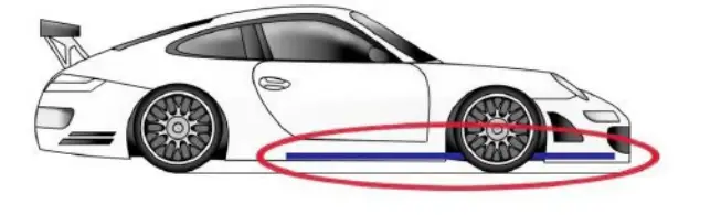
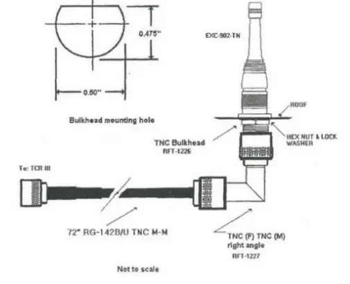
VMPS Antenna
- Must be fitted to the top surface of the vehicle roof within 200mm of the roof centerline.
- All other antennas on Car, other than the supplied LTE antennas, must be installed at least 240 mm from center of IMSA VMPS antenna.
- Include a visualized restriction zone around the VMPS antenna.
- Antenna must be mounted with heading in the driving direction.
- See BSSM for additional information.
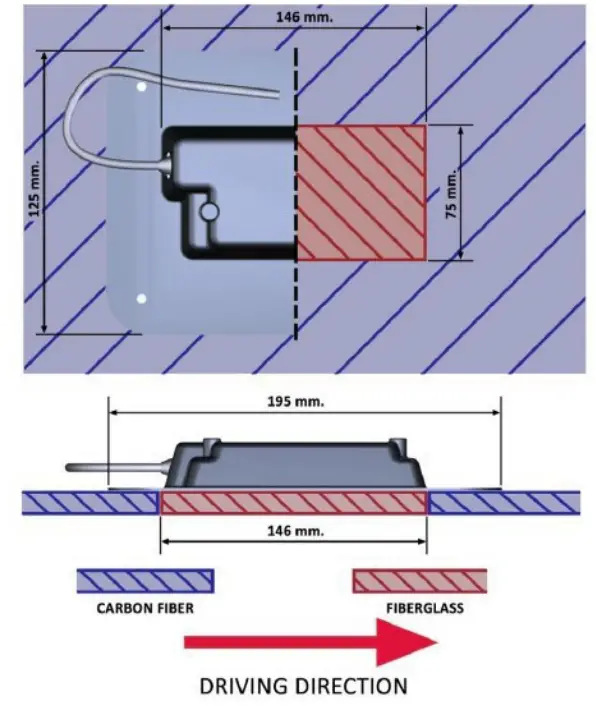
X2 Transponder
- The longitudinal axis of the transponder must be parallel with the longitudinal axis of the vehicle and the label side of the transponder must face the ground.
- A non-conductive window may be placed between the transponder and the ground. IMSA highly recommends an Aramid (Kevlar) or fiberglass window.
- The window must extend beyond the edge of the carbon fiber mounting bracket available for purchase from IMSA.
- If two transponders are fitted in the car, must detail both transponder locations.
Fuel Flow Meter
- Submitted images of mounting bracket and location will be reviewed by IMSA for approval.
- Must be mounted near engine, isolated from vibration and heat.
- Each supply line requires its own individual sensor.
- Low pressure supply line only.

- Low pressure supply line only.
- (GT-100-01) User Guide and Datasheet.zip
Leader Light System
- 9” W x 8” H area must remain clear of any other decals, wrap or graphics.
- Must be clearly visible from side.
- XAP panel controller box must be in cockpit.
XAP NTX Marshalling Display
- Must be in a secure location and visible to all drivers when in a seated position.
Accident Data Recorder
- Must be consistent with FIA Homologated location.
- Must be affixed to hardpoints with fasteners.
- Must be oriented in accordance with MoTeC ADR2 documentation.
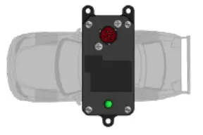
Orientation
The ADR2 must be installed in alignment with the primary axes of the vehicle. The orientation is specified in the device configuration; see Orientation Tab. The position is defined using the orientation of the connector and the single point mount with respect to the vehicle axes. FIA has prescribed installation as shown.
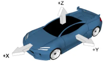
Primary vehicle axes
- X-axis, longitudinal, positive forward acceleration
- Y-axis, lateral, positive left acceleration
- Z-axis, vertical, positive upward acceleration
FIA prescribed mounting orientation
ADR2 mounting orientation where the connector points towards the ceiling and the single mount points towards the left of the vehicle.
Safety Light Antenna
- Must be on the car roof.
- A minimum of 240mm away from the VMPS antenna and 150mm away from other antennas.
- Include a visualized restriction zone around the Safety Light antenna.
- Following the diagram below (a ground plane is not required)
Wheel Speed Sensors
- Must have one per each wheel.
- System layout based on the implementation of scrutineering wheel speed, document selected configured as detailed below:
- From Bosch M5 ABS TTL Output
- Must detail wiring configuration including ground circuit in Wheel speed sensor system layout.
- Active-type Hall effect wheel speed sensors
- Must detail trigger wheel pattern in Wheel speed trigger wheel detail.
- Must detail sensor type in Wheel speed sensor system layout.
- Must detail installation in Wheel speed sensor installed.
- Signal Splitter from ABS
- Must detail signal splitter device details and installation in Wheel speed sensor system layout.
- Must detail wiring configuration including ground circuit in Wheel speed sensor system layout.
- From Bosch M5 ABS TTL Output
- Must detail trigger wheel pattern in Wheel speed trigger detail.
- See BSSM for additional information.
Engine Speed sensors
- Trigger wheel must include 30-60 teeth and must include 1-4 missing teeth in 1 spot around the wheel.
- If choosing an inductive sensor, the depth of the missing tooth gap must be half the depth of the normal gaps.
- Must detail trigger wheel pattern in Engine speed trigger wheel detail.
- Must specify sensor type
Fuel Proximity Sensor
- Must specify sensor type and pull up/down requirements
TPMS
- Must have one sensor per wheel.
- Must include system manufacturer per IMSA approval.
- Must detail gateway information and mounting details, if utilizing in TPMS information.
- Must detail number and placement of receivers and ECU in TPMS system layout overview.
LTE Telemetry
- Must indicate whether this will be a shared or standalone system in LTE Telemetry Module.
- LTE telemetry radio must be mounted in a dry area away from direct heat sources, and with the status LEDs plainly visible.
- LTE external antenna is recommended to be mounted inside of VMPS antenna restriction zone.

- LTE external antenna is recommended to be mounted inside of VMPS antenna restriction zone.
- LTE internal antenna must be mounted under glass, inside the car. The antenna must have a direct view of the sky.
- The antenna may be covered in vinyl.
- A location under a heated windscreen is acceptable.
- See BSSM for additional information.
Wiring Loom
- Must include diagram of all portions of wiring loom including pinout.
- Must include Block Diagram of CAN routing including components and lengths for all scrutineering busses
Documents / Resources
 |
IMSA VMPS Technical Eligibility Form Appendix [pdf] Instructions VMPS Technical Eligibility Form Appendix, VMPS, Technical Eligibility Form Appendix, Eligibility Form Appendix, Form Appendix, Appendix |