![]()
![]()

RAM 3500 TIP Start Diesel Module LED Flashing RED
FTI-CDP1 – Vehicle Coverage and Preparation Notes
| Make | Model | Year | Install | CAN | Lights | IGN | Hood | I/O Changes |
| DL-CH8 | 2013-17 | Park / Auto | Green White/Blue | |||||
| RAM | 3500 TIP Start Diesel | Type 1 | OBD-II | Type B | BCM | BCM | ||
Firmware: Covered vehicles use BLADE-AL(DL)-CH8, confirm application, flash module, and update the controller firmware before installing.
CAN: Type 1 vehicles use CAN connections in harness at OBD-II, the included CAN extension is not required for this install type.
Lighting: Type B parking lights use the 10-pin connector, please ensure that the unused 6-pin connector is properly secured for safety.
Ignition: Common ignition provisions are listed in the BLADE diagram, ignition is also available at the vehicle BCM (connector C5/E, pink/white, pin #27),
Hood: Hood status wire is available at the vehicle BCM, connector C1, pin #11 (violet/blue).
FTI-CDP1 – Installation and Configuration Notes
A…………………. Required CAN connections.
B………………… Not required.
C………………… Vehicle hood status ( – ).
D………………… Ignition jumper, CONNECT TO PINK.
E………………… Ignition connection.
BLADE FEATURE COVERAGE

| IMMOBILIZER DATA | |
| PRIORITY UNLOCK | |
| DOOR LOCK | |
| DOOR UNLOCK | |
| ARM OEM ALARM | |
| DISARM OEM ALARM | |
| DOOR STATUS | |
| RAP SHUTDOWN | |
| BRAKE STATUS | |
| E -BRAKE STATUS | |
| TACH OUTPUT | |
| GLOW PLUG STATUS | |
| SECURE TAKEOVER | |
| PARKING LIGHTS |
- FT-DAS required for manual transmission.
- BOTH red and red/white MUST be connected with a high current application.

CM900AS/900S Jumper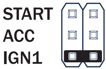
DL-CH8 – Type 1 2013-17 RAM 3500 TIP Start Diesel
 LED Programming Error Codes
Module LED flashes RED during programming
- 1x – CAN Error, check CAN wiring and voltages
- 2x – Key code not learned, confirm unlock sent, check CAN
- 3x – No immobilizer data, check immo data connection
- 4x – No IGN, check IGN connection
- 5x – VIN not found, check CAN connections
- 6x – No immobilizer data, check immo data connection
- 7x – Not the same key, use only one key for programming
- 8x – No immobilizer data, check immo data connection
- 9x – No immobilizer data
- 10x – Klon error, redo Klon
INSTALLATION GUIDE
ALL IN ONE DODGE/RAM
Patent No. US 8,856,780 CA 2759622
COM-BLADE-AL(DL)-CH8-EN
Doc. No.: ##65995## 20191004
MODULE PROGRAMMING PROCEDURE – WITH KLON
- Close the driver’s door.

Reopen the driver’s door to activate the data bus. - Press UNLOCK on the OEM remote.

If the vehicle is not equipped with an OEM remote, press the module programming button. - Please wait, the LED will blink BLUE once [1x].

- Turn the key to the ON position.

- Wait, LED will turn solid RED .

- Turn the key to the OFF position.

- Remove the key.

- Insert the key into the ignition.

- Turn the key to the ON position.

- Please wait, the LED will flash BLUE.

- Turn the key to the OFF position.

- WARNING:
 Turn off the power last.
Disconnect RS from vehicle. - Connect the RS to the computer and proceed with extended programming.

- WARNING: Do not press RS programming button.
 Connect power first.
Connect RS to vehicle. - Turn the key to the ON position.

- Wait, the LED will turn solid BLUE for 2 seconds.

- Turn the key to the OFF position.

- Turn the key to the START position.

- Turn the key to the OFF position.

- Module Programming Procedure Completed.
WARNING: READ BEFORE REMOTELY STARTING YOUR VEHICLE
IMPORTANT
- All vehicle doors must be closed and locked prior to remote start sequence. Failure to comply will result in remote starter malfunction.
TAKE OVER PROCEDURE – TO THE VEHICLE OWNER
- All vehicle doors must be closed and locked prior to the remote start sequence.

- Press UNLOCK on the replacement remote.

- Press UNLOCK on the replacement remote.
- TIME RESTRICTION
 N
N

Within 45 SECONDS of the previous step:
Open the vehicle door. Enter the vehicle.
Close the vehicle door.
Insert the key into the ignition.
Turn the key to the ON position.
Press and release the BRAKE pedal. - Taking possession procedure completed.
 Failure to complete the procedure within the time limit will result in the vehicle engine being turned off.
Documents / Resources
 |
idatalink RAM 3500 TIP Start Diesel Module LED Flashing RED [pdf] Installation Guide FTI-CDP1, DL-CH8, RAM 3500, RAM 3500 TIP Start Diesel Module LED Flashing RED, RAM 3500, TIP Start Diesel Module LED Flashing RED, Diesel Module LED Flashing RED, Module LED Flashing RED, Flashing RED |