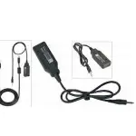
![]() OPC-617 External Terminal Connection Cable
OPC-617 External Terminal Connection Cable
Instructions
OPC-617 External Terminal Connection Cable
Install the OPC-617 as shown below.

OPTIONAL CABLE PIN ASSIGNMENT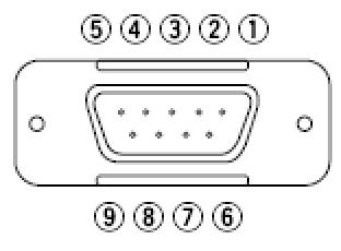
- LCD backlit cont. IN
- AF OUT
- Det. AF OUT
- Mod. IN
- PTT control IN
- Horn drive cont. OUT
- AF GND
- Det. AF GND
- Mod. GND
 Additional Notes
| DB-9 Connector Pins | Notes |
| Pin 2 | To find a suitable AF level, turn the Vol Knob OFF Change the AF Min level (in Set Mode) until a suitable level is found. |
| Pin 4 | Solder Bead F for data. Solder Bead D for AF in. |
| Pin 5 | To enable an external PTT: In Common -> Expert, set EPTT/FTSW to EPTT. If you require a delay after releasing PTT, set a value in the EPTT Delay Timer. |
| Pin 6 | To set Pin 6 as a Carrier Operated Relay: Disable the 2/5-tone function for the selected channel. In Common -> Expert, set RX EXO to ON and the Delay Timer to OFF. This enables COR to react instantly to the signal when it switches on and off. |
F121/F221, F121S/F221S OPC-617 Horn Honk Connections
For 2-Tone and 5-Tone Signaling

Programming
For both 2-Tone and 5-Tone:
- Navigate to RX Code CH and set the EXO to ON.
- Navigate to Common -> Expert and set RX EXO to OFF.
OPC-617 Remote Connections for 2-Tone/5-Tone For the F521/F621 Radio

Additional Notes
| DB-9 Connector Pins | Notes |
| Pin 2 | Program radio as in Pin 6 COR programming. 1. To find a suitable AF level, turn the Volume Knob off. 2. Change the AF Min Level (in Set Mode) until a suitable level is found. |
| Pin 4 | Solder Bead F for data. Solder Bead D for AF in. |
| Pin 6 | To set Pin 6 as a 2/5 tone operated relay: 1. Set the 2-Tone or 5-tone RX Code Ch EXO to ON. 2. Set Mode -> Horn to ON. 3. Common -> EXO setting doesn’t matter. 4. The Common -> EXO Delay Timer sets how long Pin 6 stays low after signal. |
OPC-617 Ignition Connections for F121/F221 Series Radios
To enable the radio to turn on when the ignition switch is turned on, connect the OPC-617 11 pin connector to J6 on the main PCB. Then connect DB-9 pin 1 to the
ignition switch. Be sure to connect DB-9 pin 1 to a switched-on high contact on the ignition switch.

After making connections, enable in the EXPERT window by setting the DIM / IGSW field to IGSW.
OPC-617 Remote Connections for 2-Tone/5-Tone For the F521/F621 Radio

Additional Notes
| DB-9 Connector Pins | Notes |
| Pin 2 | Program radio as in Pin 6 COR programming. 1. To find a suitable AF level, turn the Volume Knob off. 2. Change the AF Min Level (in Set Mode) until a suitable level is found. |
| Pin 4 | Solder Bead F for data. Solder Bead D for AF in. |
| Pin 6 | To set Pin 6 as a 2/5 tone operated relay: 1. Set the 2-Tone or 5-tone RX Code Ch EXO to ON. 2. Set Mode -> Horn to ON. 3. Common -> EXO set to OFF. 4. The Common -> EXO Delay Timer sets how long Pin 6 stays low after signal. |

Additional Notes
| DB-9 Connector Pins | Notes |
| Pin 2 | 1. Program radio as in Pin 6 COR programming (below). 2. Assign 1 key as RX Speaker and turn on. 3. To find a suitable AF level, turn the Volume Knob off. 4. Change the AF Min Level (in Set Mode) until a suitable level is found. |
| Pin 4 | Solder Bead F for data. Solder Bead D for AF in. |
| Pin 6 | To set Pin 6 as a Carrier Operated Relay: 1. Set the 2-Tone RX Code Ch EXO to ON or OFF. 2. Set Mode -> Horn to ON. 3. Common -> To EXO to ON. 4. Common -> EXO Delay Timer sets how long Pin 6 stays low after signal. 5. Disable 2-Tone in the Memory CH. |
Remote OPC-617 Connections for the F1721/F1821 Radio

Additional Notes
| DB-9 Connector Pins | Notes |
| Pin 2 | • Program radio as in Pin 6 COR programming. • Assign a key as RX Speaker in programming. Key must be activated for COR. • In Key & Display, set the Amp to OFF. • To find a suitable AF level, turn the Volume Knob OFF and change the AF Min Level (in Set Mode) until a suitable level is found. |
| Pin 4 | • Solder Bead F for tones and data (generally, a data line or frequencies greater than 300Hz). • Solder Bead Sig for signals of 300Hz or less (sub-audible tones or low speed data and low-level voice). |
| Pin 6 | To set Pin 6 as a 2-Tone or 5-Tone relay: 1. Set 2Tone/5Tone -> RX Code -> EXO to ON. 2. Set the Set mode -> Horn to ON. 3. Set Common -> EXO to OFF. 4. Set Common -> EXO Delay Timer to the desired delay time. To set Pin 6 as a Carrier Operated Relay: 1. Set 2Tone -> RX Code -> EXO to OFF. 2. Set the Set mode -> Horn to ON. 3. Set Common -> EXO to ON. 4. The Common -> EXO Delay Timer sets how long Pin 6 stays low after receiving the signal. 5. Disable 2Tone in Memory CH. |
![]() ©2007 Icom America Inc.
©2007 Icom America Inc.
Icom America, Inc.
2380 116th Ave NE
Bellevue, WA 98004
425.540.6087
Documents / Resources
 |
iCOM OPC-617 External Terminal Connection Cable [pdf] Instructions OPC-617, OPC-617 External Terminal Connection Cable, External Terminal Connection Cable, Terminal Connection Cable, Connection Cable, Cable |