ML601
Embedded low power consumption LoRa module manual
0V1
| Date | Author | Version | Note |
| June 21st ,2021 | Yebing Wang | V0.1 | First edition, modules’ definition of hardware and request of function. |
Introduction
The ASR6601 is a LoRa soc chip.
The interior is implemented by core of Cortex M4 with the software core of Semtech’s LoRa transceiver SX1262. The module can achieve 868(for EU)/915Mhz frequency band communication. The module implements the LoRa device with CLASS A,B,C protocol, DTU and various private protocols. Class A, B,C protocol is nonstandard Lorawan protocol and is only suitable for our gateway. The MCU inside the module is powerful, with a 48Mhz master frequency and 16kbytes Sram,128k flash, making a big leap in performance from the previous ASR6505. In order to reduce the cost of hardware, the Open MCU scheme can be used directly inside by user without expand MCU.
The module’s maximum receiving sensitivity is up to – 140dBm, maximum transmit power up to 14dBm@868MHz(for EU) Band / 94dBuV/m@3m@915MHz Band.
Main feature:
- Maximum reception sensitivity is up to -148dBbm
- Maximum launch power is 14dBm@868MHz(for EU) Band / 94dBuV/m@3m@915MHz Band.
- Maximum transmission speed: 62.5kbps
- Minimum dormant current: 2uA
- Maximum master frequency: 48Mhz
- 16kbytes Sram, 128k Flash
Basic parameters of the module
| Classify | Parameter | Value |
| Wireless | Launch power | |
| I 4dBm@868MHz(for EU) Band | ||
| 94dBuV/m@3m@915MHz Band. | ||
| Receive sensitivity | -124dbm@SF7(5470bps) | |
| -127dbm@SF8(3125bps) | ||
| – I 29.5dbm@SF9(1760bps) | ||
| Hardware | Data interface | UART /SPI/IIC/PWM/I0&etc. |
| Power range | 3-3.6V | |
| Current | 120mA | |
| dormant current | 2uA | |
| Temperature | -20-85 | |
| Size | I 8.2x18x2.5mm | |
| Software | Networking protocol | CLASS A, B, C, DTU & private protocol |
| Encryption type | AES128 | |
| User configuration | AT instruction |
Hardware introduction
Outline of module

Notes for Hardware design:
- Try to supply the module using separate power supplies with low noise LDO such as SGM2033.
- The supply current of the module must be >120mA, not including the rest system current.
The definition of pin
| Pin number | Name | Type | Description |
| I | GND | Power | System GND |
| 2 | GPI033 | () | This 10 function is high output at module wake up and 10 low during hibernation. For 9V battery power supply cases. for low power consumption. Power is supplied by LIX) when the module is dormant and by DCDC when the module wakes up. External LED. usually high. put low when lighting. |
| 3 | GPI037 | 1 | I. For the external MCU to wake up the LoRa module. (Usually high level. when the module needs to wake up. the MCU output I ms pulse (low level effective) to the module. All mode pull-down low levels above 2S recovery port rate default): 2. For the external MCU tells Lora is ready to receive AT instructions: |
| 4 | GPI032 | 0 | I. To wake up external MCU. 2. Use to tell the MCU. Lora module has been awakened to accept AT instructions: Lower wireless data. finish sanding. and hibernation |
| 5 | GPTIMO_CH I SP10_CS GPI001 |
I0 | PWM output SPI chip selection 10 |
| 6 | GPTIMO_CHO SP1O_CLK GP1000 | I0 | PWM output SPI clock I0 |
| 7 | GPTIMO_CH3 SPIO_RX GPI003 | I0 | PWM output SPI input I0 |
| 8 | BOOT GPTIMO_CH2 SPIO_TX GP1002 | I0 | Choose BOOT( internal pull-down). PWM output SP1 output I0 |
| 9 | SWD GP1006 | I0 | Simulator debugging SWD t pull-up ) I0 |
| 10 | SWC GP1007 | 0 | Simulator debugging SWC ( pull-down ) 10 |
| II | VCC | 0 | Power input 3.3V. Maximum peak current150mA. |
| 12 | GND | Power | System GND |
| 13 | UAFtTO_RX GP1016 | I0 | Serial port 0 receive 10-download-print |
| 14 | UARTO_TX GP1017 | I0 | Serila port 0 send 10-download-print |
| 15 | 11CO_SCL GP1014 | I0 | IICO clk 10 |
| 16 | 11CO_SDA GY1015 | I0 | IICO DATA 10 |
| 17 | /RST | 0 | System reset. low effectiveness |
| 18 | GP1009 GPTIMI CHI | 0 | I0 PWM output |
| 19 | GP105 ADC2 |
I0/A | I0 ADC CH2 |
| 20 | ADC3 GPI004 | A/I0 | ADC CH3 10 |
| 21 | LPUART_RX GPI060 | I0 | Low Power UART RX 10-AT interactive |
| 22 | LPUART_TX GP1047 | I0 | Low Power UART TX 10 |
| 23 | OPAO_INP GP1045 | MO | Operational amplifier 0. positive enter point I0 |
| 24 | OPAO_INN GP1044 | .A/I0 | Operational amplifier 0. negative enter point I0 |
| 25 | OPAO_OUT GP1010 | MO | Operational amplifier 0. output point 10 |
| 27 | GND | Power | System GND |
| 28 | ANT | RF | Antenna wire |
| 29 | GND | Power | System grounding line |
Hardware size

Electrical character
| Parameter | Condition | Minimum | Normal | Maximum | Unit |
| Working voltage | 3 | 3.3 | 3.6 | V | |
| Working current | Continuous send |
120 | mA | ||
| dormant current | RTC work | 2 | uA |
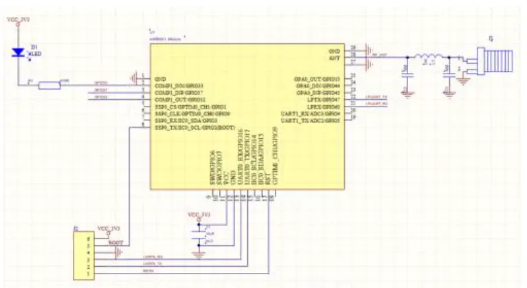
Reference design
Parameter of function.
- Support wireless transmission
- Changeable serial port rate and test bit
- Support for transmission data encryption and decryption
- Support for frequency and rate-setting
- Support the selective preservation of setting parameters. The MCU control the module does not need to be saved, and it is used separately as a transmission module
- Support the use of external MCU control modules and independent modules
- The serial port rate, Lora rate, Lora frequency, and secret key within the same transmission combination need to be consistent, and the inconsistency will lead to anomalies
- LED lamp (GPIO33) flash at 2S frequency
- Pull GPIO32 down when sending data, sent and dormant
- Export “AT + START\r\n”, until it receives this command Directive configuration and data transfer
- The recovery default serial port rate is 38400, no verification function
Regional division of FLASH
Internal Flash has a total of 128kbytes, page in size of 4k.
| Region | Range of region | Byte | Note |
| DTU routine are |
0x0800_0000-0x0801_EFFF | 124K | DTU routine is |
| INFO | 0x0801_F000-0x0801_FFFF | 4K | Store some user information |
Usage of module
Module use can be controlled by an external MCU and as independent modules using two, with an arbitrary combination of port rate and rate, the packet length transmission supports a maximum of 1K (1023Byte) byte data.
- External MCU control
The default GPIO32 of the power is high, the GPIO32 is pulled down during the data transmission process, and the GPIO32 is high, which can be determined here whether the broken module is dead, the timeout should be greater than 5.26S (sending 1 K bytes at SF9,2400 baud rate). - When the transmission data is greater than 1K, the 1K data is sent first to continue to send the remaining data when the GPIO32 is restored to high, so that the circular transmission is sent.
AT instruction
(Note: Sending the command needs to return the line and return the AT command to return the line)
7.1,Enter into AT instruction mode
| Serial port | Format | Note |
| Send | +++ | The start and end byte of a frame must be with an ending with three consecutive ‘+’+”\r\n”, send a character ‘a’ between10ms to 1s |
| Send | a | The ‘a’ must end with the frame start byte + “\ r \ n” and if the + + ‘character is not received in module 1S, the’ + + +’is issued as a data transmission |
| Return | AT+ENAT=OK | Enter into command mode |
7.2, Set the serial port rate
Note: After this step, the serial port returns OK or ERR, MCU according to the previous port rate, and check bit to synchronously initialize the corresponding port rate and check bit after receiving the successful setup command.
| Serial port | Format | Note |
| Send | AT+BAUD=9600,0 | 2400、4800、9600、14400、19200、38400(default)、7600、115200 optional 0-No check bit(default) 1-Check odd 2-Check even |
|
Return |
AT+BAUD=OK | Correct return |
| AT+BAUD=ERR | Wrong return | |
| Send | AT+BAUD=? | Inquiry |
| Return | AT+BAUD=9600,0 |
7.3, Set the Lora frequency interval
| Serial port | Format | Note |
| Send | AT+FREQ=4400
|
470Mhz span:4300~5100 868Mhz(for EU) span:8600~9200 Default; 4400 |
|
Return |
AT+FREQ=OK | Correct return |
| AT+FREQ=ERR | Wrong return | |
| Send | AT+FREQ=? | Inquiry |
| Return | AT+FREQ=4400 |
7.4, Set the Lora rate
| Serial port | Format | Note |
| Send | AT+RATE=7 | 7(5470bps) /8(3125bps) /9(1760bps)optional Default:7 |
|
Return |
AT+RATE=OK | Correct return |
| AT+RATE=ERR | Wrong return | |
| Send | AT+RATE=? | Inquiry |
| Return | AT+RATE=7 |
7.5, Set the working mode
| Serial port | Format | Note |
| Send | AT+WORKMODE=1 | After sending the data in dormant mode |
|
Return |
AT+WORKMODE=2 | Post the data delay dormancy mode |
| AT+WORKMODE=3 | No dormant mode (default) | |
| Send | AT+WORKMODE=OK | Correct return |
| Return | AT+WORKMODE=ERR | Wrong return |
| Send | AT+WORKMODE=? | Inquiry |
| Return | AT+WORKMODE=1 |
7.6, Set the Lora packet length
| Serial port | Format | Note |
| Send | AT+LORALENTH=240 | Set the Lora data per packet(32~240) |
|
Return |
AT+LORALENTH=OK | Correct return |
| AT+LORALENTH=ERR | Wrong return | |
| Send | AT+WORKMODE=? | Inquiry |
| Return | AT+WORKMODE=240 |
7.7, Set up the key
Fixed 16 bytes and 16 decimal numbers (16 characters) with the encryption key to resolve the data correctly.Query is not supported.
| Serial port | Format | Note |
| Send | AT+DATAKEY=Qqert,91234567890 | Support for numbers, English, and English characters. Default: All 0 |
|
Return |
AT+DATAKEY=OK | Correct return |
| AT+DATAKEY=ERR | Wrong return | |
| Send | AT+DATAKEY=? | Inquiry |
| Return | AT+DATAKEY=ERR |
7.8, Save the parameters set above
Note: Perform this command to save the previously set AT instruction parameters.
| Serial port | Format | Note |
| Send | AT+SAVE | Save the above set AT instruction parameters |
| Return | AT+SAVE=OK |
7.9, clear the above set parameters- -the restart takes effect
Note: restore default except the above setting AT instruction parameters.
| Serial port | Format | Note |
| Send | AT+RESTORE | Clear the above set AT instruction parameters to restore the default values |
| Return | AT+RESTORE=OK |
7.10, Exit the AT instruction mode
Note: This step indicates that the setting is complete and the module receives the instruction into transmission mode. The setting was not complete midway, and the previous setting was also successful.
| Serial port | Format | Note |
| Send | AT+EXAT | Exit the at instruction mode |
| Return | AT+EXAT=OK |
Note: The parameters configured through the AT instruction will not be automatically saved, the configured parameters after power again will restore the default, which need to be saved through AT + SAVE.
Restores the default serial port rate 38400 and no checked
GPIO37 pin holding low level above 2S can restore the default serial port rate and return to AT + BAUD=38400,0 + return line.
Please take attention that changes or modifications not expressly approved by the party responsible for compliance could void the user’s authority to operate the equipment.
This device complies with Part 15 of the FCC Rules. Operation is subject to the following two conditions: (1) this device may not cause harmful interference, and (2) this device must accept any interference received, including interference that may cause undesired operation.
The module is limited to OEM installation ONLY The OEM integrator is responsible for ensuring that the end-user has no manual instruction to remove or install-module.
When the FCC identification number is not visible when the module is installed inside another device, then the outside of the device into which the module is installed must also display a label referring to the enclosed module. This exterior label can use wording such as the following: “Contains FCC ID: 2AZ6I-ML601” and the information should be also contained in the devices’ user manual.
Documents / Resources
 |
Hyeco Smart Tech ML601 Embedded Low Power Consumption Lora Module [pdf] User Manual ML601, 2AZ6I-ML601, 2AZ6IML601, ML601 Embedded Low Power Consumption Lora Module, Embedded Low Power Consumption Lora Module, Consumption Lora Module, Lora Module |


