HUBERT A1110-P4 Multi Amplifier Adapter

Product Information
Specifications
- Model: A1110-P4
- Product Name: Multi-Amplifier-Adapter
- Version: v2
Introduction
Device Description
- The A1110-P4 contains ballast resistors required for parallel connection. A temperature-controlled fan provides the necessary cooling. An interlock connection with the involved power amplifiers ensures that the amplifiers are only ready for operation when the A1110-P4 is switched on and thus cooling is active. In case of an over temperature, the amplifiers are muted.
- It is imperative to observe the general and product-specific safety instructions in Chapter 2.
Additional information can also be found in the White Papers
- WP-4 Balanced Input
- WP-5 More voltage and current
Scope of Delivery
- These operating instructions
- 4 pcs. 3-wire cable, BNC/XLR (Cable A)
- 3 pcs. 3-wire cable, BNC/XLR (Cable B)
- 4 pcs. 2-wire cable, BNC/BNC
- 1 pcs. 2-wire cable, BNC/BNC (Cable C)
- 6 pcs. BNC T-adapter (f-m-f)
- 1 pcs. BNC T-adapter (f-f-f)
- 4 pcs. 1-wire cable, stranded wire 6mm² with M8 cable lugs red
- 4 pcs. 1-wire cable, stranded wire 6mm² with M8 cable lugs black
- Power cable
For Your Safety
Used Symbols and Notations
Warning Level
![]() DANGER
DANGER
Type and source of danger
Indicates an imminently hazardous situation which, if not avoided, will result in death or serious injury.
![]() WARNING
WARNING
Type and source of danger
Indicates a potentially hazardous situation which, if not avoided, could result in death or serious injury.
![]() CAUTION
CAUTION
Type and source of danger
Indicates a potentially hazardous situation which, if not avoided, could result in minor or moderate injury or property damage.
![]() NOTICE
NOTICE
Type and source of danger
Indicates important information about the product or procedures that should be considered for the correct functioning of the device.
Used Warning Symbols
 Warning about a dangerous voltage
 Warning about general danger
 Description of what should be done or what to pay attention to
General Safety Advice
- The following general safety instructions must be observed during the use of this device. Disregarding this advice or specific warnings in this manual will violate safety standards in the intended uses of this equipment.
- The manufacturer is not responsible for consequences resulting from disregarding the advice and warnings.
DANGER
Electrical voltage – Danger of electric shock
Parts under voltage:
Always cover all parts under voltage that inevitably arise during operation.
Touching of cables, sockets and plugs:
Never touch the contacts of cables, sockets or plugs directly after disconnecting them, as there is a risk of electric shock.
Contact between amplifier outputs and PE:
Touching an amplifier output and PE at the same time can result in a life threatening electric shock.
Earth the device:
The device fulfills the requirements for protection class I. To avoid the risk of electric shock, the device housing must be earthed and therefore always operate the device via the supplied three-core power cable with protective conductor. The mains cable may only be plugged into a grounded socket with a protective earth contact. An interruption of the protective earth conductor inside or outside the device reduces the safety of the device and is prohibited.
Safety Regulations for the work with electrical equipment:
- Disconnect mains!
- Prevent reconnection!
- Test for absence of harmful voltages!
- Ground and short circuits!
- Cover or close of nearby live parts!
Devices with a heavy current connection:
Devices with a heavy current connection may only be operated via a 4-pole RCD with ≤40 ms at 5 x IΔn. If it is not possible to install the RCD in the building installation, then our device must be connected to the mains supply via a mobile distributor with the appropriate RCD.
Do not open the housing:
Covers must not be removed by the operating personnel. Maintenance and repair work is reserved exclusively for qualified service personnel.
CAUTION
Important notes
- The device must be used exclusively for its intended purpose.
- The device is only approved for operation within the connected loads specified on the type label.
- Do not insert any mechanical parts, especially metal parts, into the device through the ventilation slots.
- Protect the unit from moisture, humidity and condensation. Avoid using liquids near the device. Never connect loads while the amplifier outputs are switched on.
- Operate the device exclusively on the public power supply system (no generators/UPS).
To avoid personal injury and property damage, make sure that the equipment and components used in the test are not overloaded. Read all operating instructions for the devices used thoroughly and ensure that all defined device limits are adhered to. If there are doubts about the suitability of the devices for the test to be performed, contact the manufacturer of the device.
Intended Use
Hardware
The device is intended exclusively for use as an LF power amplifier. Typical applications are the operation as voltage and current amplifier on low impedance passive loads. Active loads are only permitted under certain conditions in agreement with the manufacturer.
CAUTION
Operation on active loads
Active loads are only permitted under certain conditions in agreement with the manufacturer.
- The device may only be operated within the technical data and under the ambient conditions specified in this manual.
- Changes to the device are not permitted without the consent and release of the manufacturer. Proper and safe operation of the device requires correct installation and careful operation. This manual is part of the device and must always be accessible to the user. Observe all safety regulations listed in this manual.
CAUTION
- The improper use leads to the exclusion of any liability claims.
- The operator alone is liable for all damage caused by improper use.
Software
‘A1110 Control’ and ‘A1500 Control’ is software developed to control and configure HUBERT power amplifier. Take into account technical data and applications described in this manual. Changes to the software are not permitted without the consent and release of the manufacturer. Proper and safe operation of the software requires correct installation and careful operation. This manual is part of the software and must always be accessible to the user. Observe all safety regulations listed in this manual.
User
Operation may only be performed by qualified persons.
CAUTION
- Reading and understanding the operating instructions
- Never use the device without having read and understood the operating instructions. Always contact the manufacturer if you have any questions.
- Qualified persons within the meaning of the safety instructions in this manual are authorized persons for commissioning and operating systems in accordance with the standards of safety technology.
DANGER
- Risk of injury in case of insufficient qualification
- Improper work can lead to personal injury and damage to property. Any work may only be carried out by persons who have the necessary training, knowledge and experience.
Operating Elements
Front Panel Elements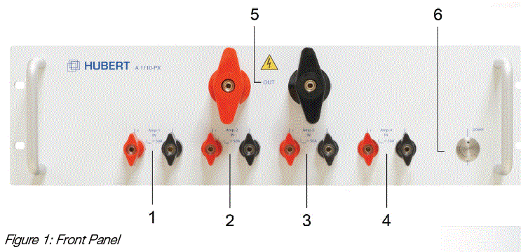
- AMP-1 IN
Pole clamp with flat knob and 4 mm safety sockets for connecting the amplifier output 1. Red socket = + signal ; black socket = – signal; max. 50A - AMP-2 IN
Pole clamp with flat knob and 4 mm safety sockets for connecting the amplifier output 2. Red socket = + signal ; black socket = – signal; max. 50A - AMP-3 IN (A1110-P4)
Pole clamp with flat knob and 4 mm safety sockets for connecting the amplifier output 3. Red socket = + signal ; black socket = – signal; max. 50A - AMP-4 IN (A1110-P4)
Pole clamp with flat knob and 4 mm safety sockets to connect the amplifier output 4. Red socket = + signal ; black socket = – signal; max. 50A - OUT
Pole terminal with flat knob and 4mm safety socket for load connection
Red socket = + signal ; black socket= – signal - POWER BUTTON
On / Off switch.
Here the change-over is made from ready to standby. The standby mode is indicated by the dim blue LED. The mains is disconnected using the switch on the back panel.
Back Panel Elements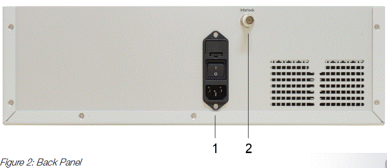
- PLUG FOR NON-HEATING APPARATUS WITH MAINS SWITCH
Power supply - INTERLOCK
BNC-socket
A remote-controlled safety system enables the disconnection of the amplifier by an external switch (break contact).
NOTICE
Do not short the interlock!
Applications
NOTICE
The interlock mode of the power amplifiers must be set to latching!
Step by Step to More Power
For the upcoming explanations a signal generator with unbalanced BNC output is required. The (+)inputs/outputs correspond to the red connectors and the (-)inputs/outputs to the black connectors.
Conventional parallel operation
Voltage Mode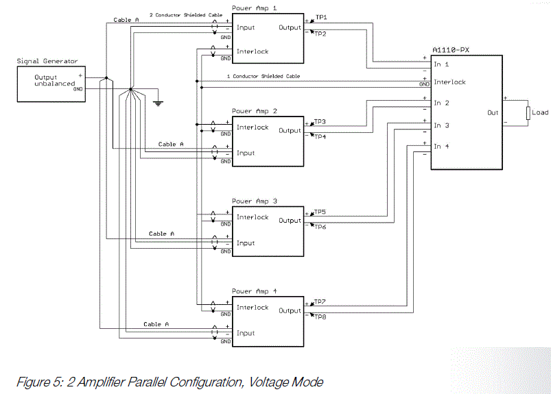
The Figure above shows the recommended wiring of the A1110-P4 with four HUBERT power amplifiers. If you received the A1110-P4 adapter with factory calibrated amplifiers, you do not need to perform steps 2 and 4.
- Connect the amplifiers and the A1110-P4 to the mains. Connect all interlock connectors to the BNC/BNC cables and the BNC T-adapter. Do not connect the inputs and outputs of the amplifiers. First switch on the mains supply at the A1110-P4 and then at the amplifier; let it warm up for 15 min.
- Check DC-Offset:
Switch on the amplifiers (amplifier on); measure the DC offset voltages at the amplifier outputs between points TP1 and TP2, TP3 and TP4, TP5 and TP6 as well as TP7 and TP8 with a multi meter. The voltage should be < 2 mV for each amplifier. Otherwise, calibration must be performed. Mute the amplifiers (amplifier off). - Connect the amplifier inputs with the XLR/BNC cable directly to the output of the signal generator using a BNC T-adapter.
- Check gain:
Set the DC signal with an amplitude of 1 VDC; switch on the amplifiers (amplifier on); measure 10 Vdc with the multi meter between points TP1 and TP2, TP3 and TP4, TP5 and TP6 as well as TP7 and TP8. If the deviation is greater than ± 10mV, calibration must be performed. Mute the amplifiers. - Connect the power outputs and the A1110-P4 inputs to the 4mm connector cables.
- Connect the load to the adapter output. Observe the required cable diameters; use minimum and equal cable lengths.
The system is now ready for operation and the amplifiers can be switched on (amplifier on). The function test should start with low signal levels (e.g. 100 mV/1 kHz). The quality of the output voltage can be checked at the corresponding monitor outputs.
Master-Slave-Betrieb
Voltage Mode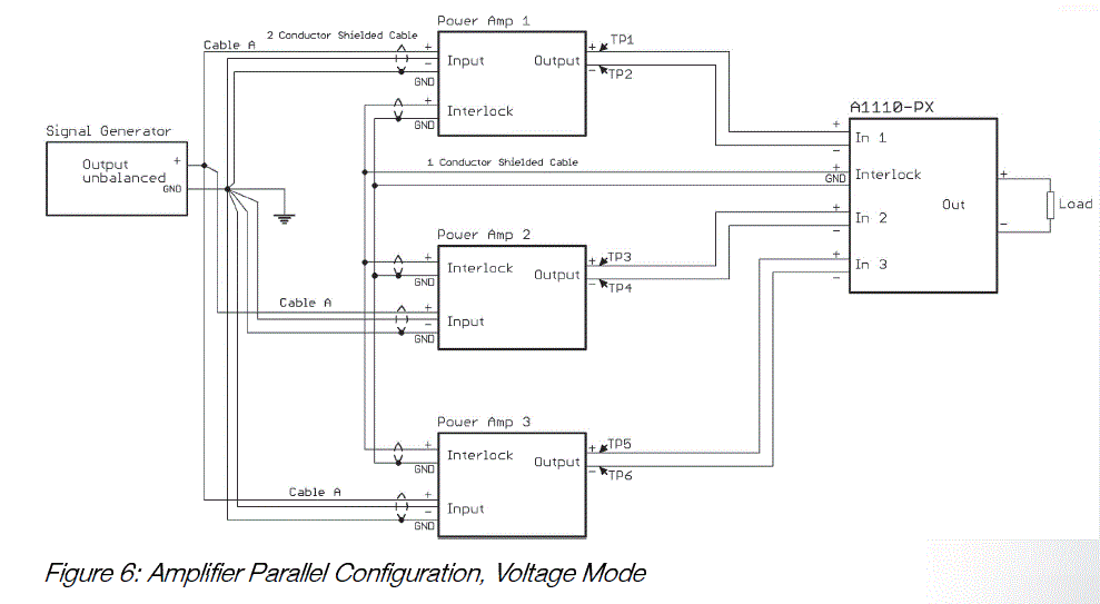
The figure above shows the recommended wiring of the A1110-P4 with three HUBERT power amplifiers. All amplifiers are working in voltage mode.
To ensure a safe operation, please observe the following steps:
- Connect the amplifiers and the A1110-P4 to the mains. Connect all interlock connectors to the BNC/BNC cables and the BNC T-adapter.
- Use the XLR/BNC cable A to connect the signal input of the master amplifier (Amplifier IN) to the signal source.
Connect the BNC T adapter to the slave out using the BNC cable C. - Connect the inputs of the slave amplifiers with the XLR/BNC cable B to the BNC T-adapter.
- Connect the parallel switch box to the amplifiers.
- Connect the amplifiers and the A1110-P4 to the power supply. Connect all interlock connections with the BNC/BNC cables and the BNC T-adapter.
- Switch on the mains power supply for all amplifiers (power), allow to warm up for 15 minutes.
- Start the control software for the master and slave amplifiers, all amplifiers are in voltage mode.
- For master amplifiers under Configuration → Parallel Mode: switch from Standalone to Master. For the slave amplifiers under Configuration → Parallel Mode: switch from Standalone to Slave.
- Switch off the output of the signal source.
- First switch on the master amplifier and then the two slave amplifiers (Amplifier On)
- Now switch the master amplifier to current mode.
- Signal processing can begin.
Switch-off procedure:
- Switch off the output of the signal source
- Now switch the master amplifier to voltage mode.
- First switch off the master amplifier and then the two slave amplifiers (Amplifier Off).
Tip: Check the signal quality, stability and distribution of the output current at the current monitor connections of the individual amplifiers.
NOTICE
Always measure the monitor outputs on the slave amplifiers differentially!
Current Mode
The figure above shows the recommended wiring of the A1110-P4 with three HUBERT power amplifiers in current mode. In this case one amplifier operates in current mode (Master) and the other two amplifiers in voltage mode (Slave).
Please follow the steps below for safe operation:
- Connect the amplifiers and the A1110-P4 to the power supply. Connect all interlock connections with the BNC/BNC cables and the BNC T-adapter. 5.
- Use the XLR/BNC cable A to connect the signal input of the master amplifier (Amplifier IN) to the signal source.
Connect the BNC T-adapter to the slave out using the BNC cable C. - Connect the inputs of the slave amplifiers to the BNC T-adapter using the XLR/BNC cables.
- Connect the parallel switch box to the amplifiers and the load.
- Connect the amplifiers and the A1110-P4 to the mains. Connect all interlock connections with the BNC/BNC cables and the BNC T-adapter.
- Switch on the mains power supply for all amplifiers (power), allow to warm up for 15 minutes.
- Start the control software for the master and slave amplifiers, all amplifiers are in voltage mode. Select the appropriate CN network for the master amplifier.
- For the master amplifier under Configuration → Parallel Mode: switch from Standalone to Master. For the slave amplifiers under Configuration → Parallel Mode: switch from Standalone to Slave.
- Switch off the output of the signal source.
- First switch on the master amplifier and then the two slave amplifiers (Amplifier On).
- Signal processing can begin.
Turn off process:
- Switch off the output of the signal source
- Switch off the Master amplifier first, then the Slave amplifier (Amplifier Off).
NOTICE
Never operate the current amplifier without load !
Tip: Check the signal quality or Stability and distribution of the output current at the current monitor terminals of the individual amplifiers.
NOTICE
Always measure the monitor outputs on the slave amplifiers differentially!
Operation with Sensing
The figure above shows the recommended wiring of the A1110-P4 with three HUBERT power amplifiers for the Sensing Option. In this case one amplifier works as Master and the other amplifiers as Slaves. The Sensing Option is controlled via the Master.
Please observe the following steps for safe operation:
- Connect the amplifiers and the A1110-P4 to the mains. Connect all interlock connectors with the BNC/BNC cables and the BNC T-adapter.
- Use the XLR/BNC cable A to connect the signal input of the Master amplifier (Amplifier IN) to the signal source.
Connect the BNC T-adapter to the Slave out with the BNC cable. - Connect the inputs of the Slave amplifiers with the XLR/BNC cables B to the BNC T-adapter respectively.
- Connect the parallel switch box to the amplifiers and the load.
- Connect the sensing input to the load.
- Switch on the mains power supply for all amplifiers (power), 15 min. warm it up.
- Start the control software for Master and Slave amplifiers, all amplifiers are in voltage mode.
- For the Master amplifier under Configuration → Parallel Mode: change from standalone to Master. In each case at the Slave amplifiers under Configuration → Parallel Mode: change from standalone to Slave.
- Switch off the output of the signal source.
- First switch on the Master amplifier, then the two Slave amplifiers (Amplifier On).
- The sensing option is only activated for the Master.
- Signal processing can begin.
Operation with “Adjustable output resistance”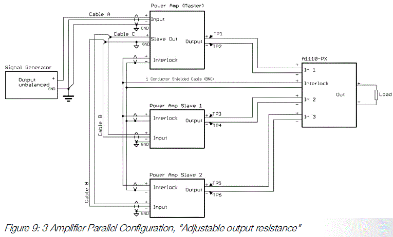
The figure above shows the recommended wiring of the A1110-P4 with three HUBERT power amplifiers for the Sensing Option. In this case one amplifier works as Master and the other amplifiers as Slaves. The Sensing Option is controlled via the Master.
Please observe the following steps for safe operation:
- Connect the amplifiers and the A1110-P4 to the mains. Connect all interlock connectors with the BNC/BNC cables and the BNC T-adapter.
- Use the XLR/BNC cable A to connect the signal input of the Master amplifier (Amplifier IN) to the signal source.
Connect the BNC T-adapter to the Slave out with the BNC cable. - Connect the inputs of the Slave amplifiers with the XLR/BNC cables B to the BNC T-adapter respectively.
- Connect the parallel switch box to the amplifiers and the load.
- Switch on the mains power supply for all amplifiers (power), 15 min. warm it up.
- Start the control software for Master and Slave amplifiers, all amplifiers are in voltage mode.
- For the Master amplifier under Configuration → Parallel Mode: change from standalone to Master. In each case at the Slave amplifiers under Configuration → Parallel Mode: change from standalone to Slave.
- Switch off the output of the signal source.
- First switch on the Master amplifier, then the two Slave amplifiers (Amplifier On).
- The adjustable output resistance option is only activated for the Master.
- Signal processing can begin.
- The “Adjustable output resistance” is set via software on the master amplifier. The set value only matches if all amplifiers are used with the parallel box. It is important that the devices have been factory calibrated together.
- For amplifiers without a common factory calibration, the value for “Adjustable output resistance” differs. The value entered is divided by the number of amplifiers used.
Operation with “Isolation Amplifier”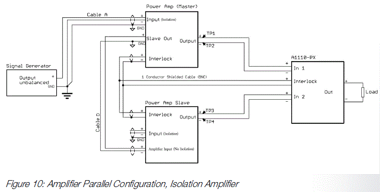
The illustration above shows the recommended cabling of the A1110-P4 with HUBERT power amplifiers with the “Isolation amplifier” option. In this case, one amplifier works as the master and the other amplifiers as slaves. The master is controlled via the isolated amplifier input. The slaves are each connected to the “Slave Out” on the master via the non-isolated amplifier input “Amplifier IN” on the back panel. The BNC bridge between “Signal Out” and “Amplifier IN” on the slaves is removed beforehand.
Support
- As a rule, our step-by-step instructions lead to a safe and stable operation of the addressed amplifier systems. The high currents in a multiple amplifier system lead to internal “floating” reference masses, which in individual cases can cause unstable operation (e.g. tendency to oscillate). Solid cabling, as explained above, minimizes the risk of instability.
- However, if you have any questions or problems with the installation or operation, you can be sure of our support.
Integration into automated test systems
- The command set for integrating the device into automated test systems is described below. A command frame is defined as follows
<length of frame> <command word> <opt. parameter> - The commands described in this section are ASCII/hex values that are transmitted as hex numbers using a terminal program (e.g. H Term, 9600 baud, 8 bits, one stop bit, no parity). These do not correspond to the SCPI standard and are defined as a pure byte protocol.
NOTICE
The connection to the device is established via USB or LAN. - The amplifier sends either the command or parameters as confirmation for a received and executed command frame (see table below). The settings for the behavior in the event of power loss shutdown and restart are saved in the device. For example, the amplifier can be configured so that it switches on again automatically after a configurable time (10-254 s) in the event of a power loss switch-off.
Remote commands
| Command frame (Tx) | Confirmation (Rx) | Note and parameter description |
| <0x03><0xD1>
<Parameter> |
<0xD1> |
|
| <0x02><0xEF> | <1 Byte> |
|
Table 1: Remote commands
Error-Codes
| Code | Description |
| 0xFC | Unauthorized command. The option may not be available. |
| 0xFD | Timeout. An incomplete command frame was received. |
| 0xFE | Unbekannter Befehl.Unknown command. |
Table 2: Error-Codes
Maintenance and Support
Maintenance and Calibration
- The device is maintenance-free.
- Factory calibration can be performed if necessary. The frequency of factory calibration is determined by the operator.
Cleaning
Clean the device only with a damp cloth. Use only solvent-free cleaning agents without aggressive components.
Support
If you have further questions about this product, please visit the support area on our website www.drhubert.com.
Decommissioning and Disposal
Decommissioning
- Turn off the device.
- Unplug the power plug.
- Remove all cables.
- Store the device in its original packaging or equivalent.
Disposal
Dispose of the device in accordance with local regulations for the disposal of electrical and electronic components.
Warranty and Disclaimer
Dr. Hubert GmbH warrants this amplifier product for normal use and operation within specifications for a period of two (2) years from date of shipment and will repair or replace any defective product which was not damaged by negligence, misuse, improper installation, accident or unauthorized repair or modification by the buyer. This warranty is applicable only to defects due to material or workmanship. Dr. Hubert GmbH disclaim any other implied warranties of merchantability or fitness for a particular purpose. Dr. Hubert GmbH will not be liable for any indirect, special, incidental, or consequential damages (including damages for loss of profits, loss of business, loss of use or data, interruption of business and the like), even if Dr. Hubert GmbH has been advised of the possibility of such damages arising from any defect or error in this manual or product.
Directives
This device complies with the relevant European Union harmonization legislation:
- EMC Directive
- Low Voltage Directive
- RoHS Directive
Contact
- Dr. Hubert GmbH
- Dietrich-Benking-Str. 41
- 44805 Bochum
- Germany
- www.drhubert.com
- +49 234 970569-0
Document History
| Document Version | Date | Changelog |
| 1 | December 2022 | First publication of English translation |
| 2 | April 2025 | Optimization for A1110-P4 |
FAQ
What should I do if I encounter a warning symbol during use?
If you encounter a warning symbol, refer to the manual for guidance on how to address the specific hazard or situation.
How do I ground the device properly?
To properly ground the device, always operate it via the supplied three-core power cable with protective conductor and plug it into a grounded socket with a protective earth contact.
Documents / Resources
 |
HUBERT A1110-P4 Multi Amplifier Adapter [pdf] Instruction Manual A1110-P4 Multi Amplifier Adapter, A1110-P4, Multi Amplifier Adapter, Amplifier Adapter, Adapter |