HK INSTRUMENTS SIRO-MOD Indoor Air Quality Transmitters User Guide
Introduction
This document contains information about configuring and using Siro indoor air quality transmitter. Before reading this guide, check that the transmitter has been installed according to the installation instructions.
Siro is available with several optional air quality sensors. The modular device can be equipped with CO2 concentration and VOC (Volatile Organic Compounds) measurements or alternatively PM (Particulate Matter) measurement, and in addition temperature and humidity measurements. Siro is available with a user interface that includes an LCD display and three pushbuttons. The device is always equipped with voltage outputs, and optionally with Modbus communication and current outputs.
The use and configuration of Siro is simple and easy by following this guide describing a Siro device with a display (-D).
Please note that this guide includes all measurement options. The device menu only shows the options that have been chosen to that particular device. You can find more information about the measurment options in the end of this document.
Schematics

The device’s physical interface includes a display and three pushbuttons.
By using the user interface, it is possible to choose the desired measurement values on the display and to adjust the settings of the device.
Note that when the menu locking jumper is installed, it is not possible to open the menu and the display will not react when pressing the ![]() button. Please see the installation instructions for more details about the locking jumper.
button. Please see the installation instructions for more details about the locking jumper.
The button functions:
![]()
Scroll up in the menu / increase the value
![]()
Scroll down in the menu / decrease the value
![]()
Open the menu / confirm (press shortly) / go back to the basic view (keep the button down/press longer

Step 1: Choosing the measurement values on the display
Step 1.1: Display View
The basic view on the display is scaled based on how many measurement values have been chosen to be viewed on the display. 1-4 measurement values can be shown simultaneously (see figure 1a). If five or more values are selected, the measurements are shown one by one and the view changes every 10 seconds. Individual measurements can be scrolled in the basic view with ![]() and
and ![]() buttons. If the buttons are unused for 30 minutes, the basic view will reappear automatically.
buttons. If the buttons are unused for 30 minutes, the basic view will reappear automatically.

Step 1.2: Choosing the measurement values
For more information about the measurements, please see page 8.
- Press
 to enter the settings menu.
 - Choose Display values.

- Choose the desired measurement values to be shown on the display.

- Scroll the menu by pressing the
 and
and  buttons.
 - Add/remove the desired measurement values by pressing the button.
- Scroll the menu by pressing the
- Choose Exit to exit the menu.

- Scroll the menu to Exit and press to return to the settings menu or keep the button down to return to the basic view.
- Scroll the menu to Exit and press
Step 2: Brightness Control
This adjusts the brightness of the display in stand-by mode.
The brightness of the display is always at the maximum level when the buttons are used.
- Press to enter the settings menu.
- Choose Brightness.

- Adjust the brightness.

- Increase/decrease the brightness by pressing and .
- Increase/decrease the brightness by pressing
- Saving the chosen brightness level and exiting.
- Save the brightness level and return to the settings menu by pressing the button or keep the button down to return to the basic view.
- The chosen brightness level will settle when the buttons have been unpressed for 30 seconds.
- Save the brightness level and return to the settings menu by pressing the
Step 3: Modbus Settings (Modbus devices only)
- Press to enter the settings menu.
- Choose Modbus.

- Choose the desired parameters in the Modbus menu.

- The parameters can be scrolled by pressing the and buttons and chosen by pressing .
Address: 1 – 247 (default = 1)
Baud rate: 9600 / 19200 / 38400 / 57600
Parity: none / even / odd
- The parameters can be scrolled by pressing the
- Choose Exit to exit the Modbus menu.

- Scroll to Exit and press to return to the settings menu or keep the button down to return to the basic view.
- Scroll to Exit and press
Step 4: Outputs
The device includes four freely configurable outputs. Current (optional) or voltage output can be chosen for each of them. The output signal has to be chosen first with a jumper (see the installation instructions), after which the output settings can be changed in the Outputs menu.
- Press to enter the settings menu.
- Choose Outputs.

- Choose measurement, scale and limits for each output.


- The menus and limits can be scrolled by pressing the and buttons. Choose the measurement and scale and set the limits by pressing the button.
- The menus and limits can be scrolled by pressing the
- Choose Exit to exit the Outputs menu.

- Scroll to Exit and press to return to the settings menu or keep the button down to return to the basic view.
- Scroll to Exit and press
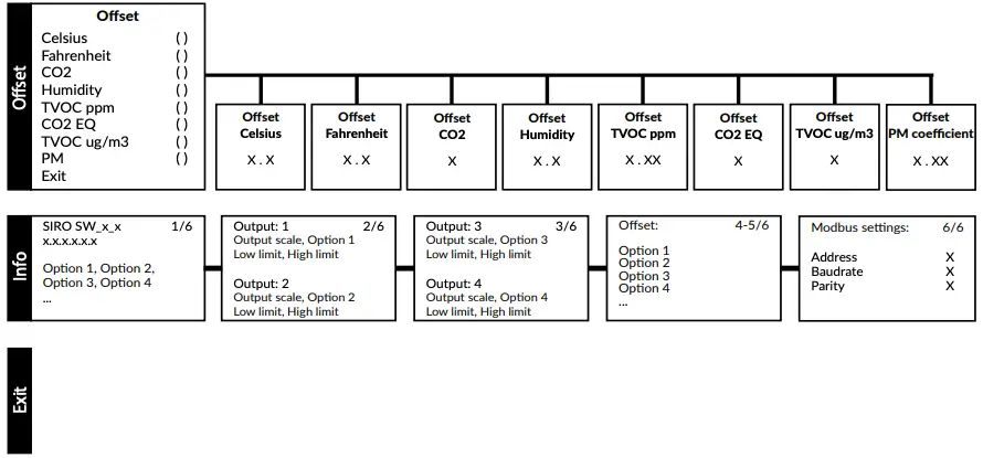
Step 5: Offset
The offset feature enables field calibration. This is necessary in applications that need annual calibration.
- Press to enter the settings menu.
- Choose Offset.

- Choose offset value for every measurement.

- The Offset menu and limits can be scrolled by pressing the and buttons. Choose the measurement and set the limits by pressing the button.
See Table 2 – Offset limits.

- The Offset menu and limits can be scrolled by pressing the
- Choose Exit to exit the Offset menu.

- Scroll to Exit and press to return to the settings menu or keep the button down to return to the basic view.
- Scroll to Exit and press
Step 6: Info View
Info view is a summary of the information and settings of the device.
- Press to enter the settings menu.
- Choose Info.

- Scroll by pressing and .
Page 1: Version number and buildup of the device.
Page 2-3: Outputs
Page 4-5: Offsets
Page 6: Modbus settings (Modbus devices only)*
- Scroll by pressing
- Press to exit the Info view.
- Press to return to the settings menu or keep the button down to return to the basic view.
- Press
Information about the Measurements
Table 3 – Additional information about the measurements

*VOC sensor is tuned for typical IAQ Mix of 22 VOCs as defined by Mølhave et al. (1997)
Table 4 – TVOC levels

Based on the German Environment Agency (UBA) reasearch.
Table 5 – PM levels

Based on the World Health Organization (WHO) research and hourly average of PM2.5 concentration.
Copyright HK Instruments 2021 w
www.hkinstruments.fi
User guide version 1.0 2021
Documents / Resources
 |
HK INSTRUMENTS SIRO-MOD Indoor Air Quality Transmitters [pdf] User Guide SIRO-MOD, SIRO, Indoor Air Quality Transmitters |


