HELTEC HT-CT62 LoRa Module

Product Specifications
- Product: HT-CT62 LoRa module
- Manufacturer: Chengdu Heltec Automation Technology Co., Ltd.
- Communication: LoRa/LoRaWAN
- Microprocessor: ESP32-C3FN4 (32-bit RISC-V architecture)
- Transceivers: Semtech LoRa SX1262
- Wireless Communication: 2.4 GHz Wi-Fi, LoRa modes
- Features: Long communication range, low power consumption, high sensitivity, low cost
Product Usage Instructions
Description
Overview
The HT-CT62 is a compact LoRa/LoRaWAN node module designed for applications requiring long-range, low-power wireless communication. It features the ESP32-C3FN4 microprocessor based on RISC-V architecture and Semtech LoRa Transceivers (SX1262), providing high sensitivity and cost-effective connectivity. The module supports 2.4 GHz Wi-Fi and LoRa modes, making it suitable for smart cities, smart farms, smart homes, and IoT projects.
Pin Definition
Pin Assignment
The pinout of the HT-CT62 module is as follows:
- Pin 1 – Description 1
- Pin 2 – Description 2
- Pin 3 – Description 3
Pin Description
Detailed description of each pin functionality and connection guidelines will be provided in the official documentation.
Specifications
Physical Dimensions
The physical dimensions of the HT-CT62 module are as follows:
- Length: XX mm
- Width: XX mm
- Height: XX mm
Resource
Relevant Resource
For additional resources, such as datasheets, application notes, and software tools, please refer to the official website of Heltec.
Contact Information
If you have any questions or need technical support, you can contact Heltec Automation Technology Co., Ltd. through the provided contact information.
Frequently Asked Questions (FAQ)
Can the HT-CT62 module be used for outdoor applications?
Yes, the HT-CT62 module is suitable for outdoor applications due to its long communication range and robust design.
Copyright Notice
All contents in the files are protected by copyright law, and all copyrights are reserved by Chengdu Heltec Automation Technology Co., Ltd. (hereinafter referred to as Heltec). Without written permission, all commercial use of the files from Heltec are forbidden, such as copy, distribute, reproduce the files, etc., but non-commercial purpose, downloaded or printed by individual are welcome.
Disclaimer
Chengdu Heltec Automation Technology Co., Ltd. reserves the right to change, modify or improve the document and product described herein. Its contents are subject to change without notice. These instructions are intended for you use.
Description
Overview
HT-CT62 is a LoRa/LoRaWAN node module with a long communication range, low power consumption, high sensitivity, and low cost. The module is composed up of ESP32-C3FN4(32-bit microprocessor based on RISC-V architecture) and Semtech LoRa Transceivers (SX1262). The module integrating 2.4 GHz Wi-Fi, LoRa modes wireless communication. HT-CT62 is a small volume, stamp hole package module, it’s the best choice for smart cities, smart farms, smart home, and IoT makers.
HT-CT62 are available in two product variants:
| No. | Model | Description |
|
1 |
HT-CT62-LF |
470~510MHz working LoRa frequency, used for China
mainland (CN470) LPW band. |
|
2 |
HT-CT62-HF |
For EU868, IN865, US915, AU915, AS923, KR920 and
other LPW networks with operating frequencies between 863~928MHz. |
Product features
- Microprocessor: ESP32-C3FN4 (RISC-V architecture 32-bit, main frequency up to 160 MHz)
- Support the Arduino development environment;
- LoRaWAN 1.0.2 support;
- Ultra low power design, 10uA in deep sleep;
- 1.27 stamp edge design for SMT;
- Good impendence matching and long communication distance.
- Integrated WiFi, network connection, onboard Wi-Fi, dedicated IPEX socket.
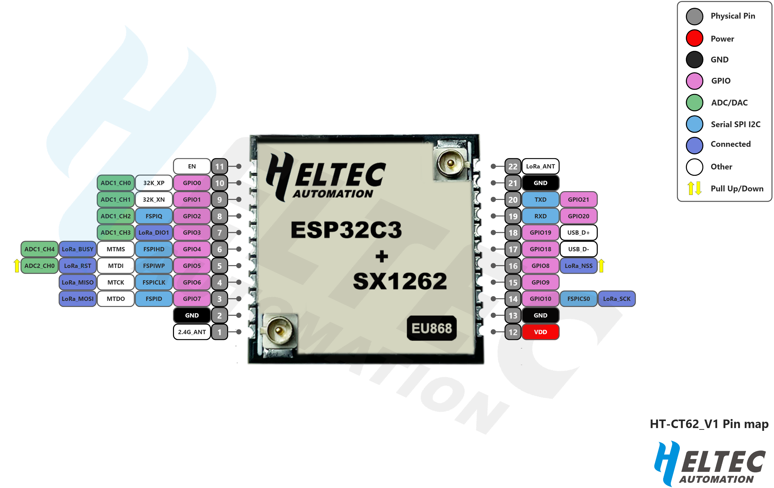
Pin Definition
Pin assignment

Pin description
| No. | Name | Type | Function |
| 1 | 2.4G ANT | O | 2.4G ANT Output |
| 2 | GND | P | Ground |
| 3 | 7 | I/O | GPIO7, FSPID, MTDO, connected to SX1262_MOSI |
| 4 | 6 | I/O | GPIO6, FSPICLK, MTCK, connected to SX1262_MISO |
| 5 | 5 | I/O | GPIO5, ADC2_CH0, FSPIWP MTDI, connected to SX1262_RST |
| 6 | 4 | I/O | GPIO4, ADC1_CH4, FSPIHD, MTMS, connected to SX1262_BUSY |
| 7 | 3 | I/O | GPIO3, ADC1_CH3, connected to SX1262_DIO1 |
| 8 | 2 | I/O | GPIO2, ADC1_CH2, FSPIQ |
| 9 | 1 | I/O | GPIO1, ADC1_CH1, 32K_XN |
| 10 | 0 | I/O | GPIO0, ADC1_CH0, 32K_XP |
| 11 | EN | I | CHIP_EN |
| 12 | VDD | P | 3.3V Power Supply |
| 13 | GND | P | Ground |
| 14 | 10 | I/O | GPIO10, FSPICS0, connected to SX1262_SCK |
| 15 | 9 | I/O | GPIO9 |
| 16 | 8 | I/O | GPIO8, connected to SX1262_NSS |
| 17 | 18 | I/O | GPIO18, USB_D- |
| 18 | 19 | I/O | GPIO19, USB_D+ |
| 19 | RXD | I/O | U0RXD, GPIO20 |
| 20 | TXD | I/O | U0TXD, GPIO21 |
| 21 | GND | P | Ground |
| 22 | LoRa ANT | O | LoRa ANT Output. |
Specifications
General specifications
| Parameters | Description |
| Master Chip | ESP32-C3FN4(32-bit@RISC-V architecture) |
| WiFi | 802.11 b/g/n, up to 150Mbps |
| LoRa Chipset | SX1262 |
| Frequency | 470~510MHz, 863~928MHz |
| Max. TX Power | 21±1dBm |
| Max. Receiving sensitivity | -134dBm |
|
Hardware Resource |
5*ADC1+1*ADC2; 2*UART; 1*I2C; 3*SPI; 15*GPIO;
etc. |
|
Memory |
384KB ROM; 400KB SRAM; 8KB RTC SRAM; 4MB SiP
Flash |
|
Interface |
2.4G ANT (IPEX1.0); LoRa ANT(IPEX1.0); 2*11*1.27
spacing Stamp hole |
| Power consumption | Deep Sleep 10uA |
| Operating temperature | -40~85 ℃ |
| Dimensions | 17.78 * 17.78* 2.8mm |
| Package | Tape & Reel Packaging |
Electrical characteristics
Power supply
| Power supply mode | Minimum | Typical | Maximum | Company |
| 3V3 pin (≥150mA) | 2.7 | 3.3 | 3.5 | V |
Power characteristics
| Mode | Condition | Min. | Typical | Max. | Company |
| WiFi Scan | 3.3V Powered | 80 | mA | ||
| WiFi AP | 3.3V Powered | 120 | mA | ||
|
TX |
470MHz, 3.3V Powered, 14dBm | 120 | mA | ||
| 470MHz, 3.3V Powered, 17dBm | 140 | mA | |||
| 470MHz, 3.3V Powered, 22dBm | 170 | mA | |||
| RX | 470MHz, 3.3V Powered | 40 | mA | ||
| Sleep | 3.3V powered | 10 | μA |
RF characteristics
Transmit power
| Operating frequency band (MHz) | Maximum power value/[dBm] |
| 470~510 | 21 ± 1 |
| 863~870 | 21 ± 1 |
| 902~928 | 21 ± 1 |
Receiving sensitivity
The following table gives typically sensitivity level of the HT-CT62.
| Signal Bandwidth/[KHz] | Spreading Factor | Sensitivity/[dBm] |
| 125 | SF12 | -134 |
| 125 | SF10 | -130 |
| 125 | SF7 | -122 |
Operation frequencies
HT-CT62 supports LoRaWAN frequency channels and models corresponding table.
| Region | Frequency (MHz) | Model |
| EU433 | 433.175~434.665 | HT-CT62-LF |
| CN470 | 470~510 | HT-CT62-LF |
| IN868 | 865~867 | HT-CT62-HF |
| EU868 | 863~870 | HT-CT62-HF |
| US915 | 902~928 | HT-CT62-HF |
| AU915 | 915~928 | HT-CT62-HF |
| KR920 | 920~923 | HT-CT62-HF |
| AS923 | 920~925 | HT-CT62-HF |
Specifications
Physical dimensions

Resource
Relevant Resource
Contact Information
- Heltec Automation Technology Co., Ltd Chengdu, Sichuan, China
- Email: support@heltec.cn
- Phone: +86-028-62374838
- https://heltec.org
FCC Statement
This device complies with part 15 of the FCC rules. Operation is subject to the following two conditions:
- this device may not cause harmful interference
- this device must accept any interference received, including interference that may cause undesired operation.
Changes or modifications not expressly approved by the party responsible for compliance could void the user’ s authority to operate the equipment.
NOTE: This equipment has been tested and found to comply with the limits for a Class B digital device, pursua nt to part 15 of the FCC Rules. These limits are designed to provide reasonable protection against harmful inte rference in a residential installation. This equipment generates uses and can radiate radio frequency energy a nd, if not installed and used in accordance with the instructions, may cause harmful interference to radio com munications. However, there is no guarantee that interference will not occur in a particular installation. If this equipment does cause harmful interference to radio or television reception, which can be determined by turn ing the equipment off and on, the user is encouraged to try to correct the interference by one or more of the following measures:
- Reorient or relocate the receiving antenna.
- Increase the separation between the equipment and receiver.
- Connect the equipment into an outlet on a circuit different from that to which the receiver is connected.
- Consult the dealer or an experienced radio/TV technician for help important announcement
Radiation Exposure Statement
- This equipment complies with FCC radiation exposure limits set forth for an uncontrolled environment. This equipment should be installed and operated with minimum distance 20cm between the radiator and your body.
- This transmitter must not be co-located or operating in conjunction with any other antenna or transmitter. Country Code selection feature to be disabled for products marketed to the US/Canada.
- This device is intended only for OEM integrators under the following conditions:
- The antenna must be installed such that 20 cm is maintained between the antenna and users, and
- The transmitter module may not be co-located with any other transmitter or antenna,
- For all products market in US, OEM has to limit the operation channels in CH1 to CH11 for 2.4G band by supplied firmware programming tool. OEM shall not supply any tool or info to the end-user regarding to Regulatory Domain change. (if modular only test Channel 1-11)
As long as the three conditions above are met, further transmitter testing will not be required. However, the OEM integrator is still responsible for testing their end-product for any additional compliance requirements required with this module installed.
Important Note:
In the event that these conditions cannot be met (for example certain laptop configurations or co-location with another transmitter), then the FCC authorization is no longer considered valid and the FCC ID cannot be used on the final product. In these circumstances, the OEM integrator will be responsible for re-evaluating the end product (including the transmitter) and obtaining a separate FCC authorization.
End Product Labeling
The final end product must be labeled in a visible area with the following”
Contains FCC ID: 2A2GJ-HT-CT62 ”
Manual Information to the End User
- The OEM integrator has to be aware not to provide information to the end user regarding how to install or remove this RF module in the user’s manual of the end product which integrates this module.
- The end user manual shall include all required regulatory information/warning as show in this manual.
List of applicable FCC rules
CFR 47 FCC PART 15 SUBPART C has been investigated. It is applicable to the modular transmitter
Specific operational use conditions
This module is stand-alone modular. If the end product will involve the Multiple simultaneously transmitting condition or different operational conditions for a stand-alone modular transmitter in a host, host manufacturer have to consult with module manufacturer for the installation method in end system.
Limited module procedures
Not applicable
Trace antenna designs
Not applicable
RF exposure considerations
This equipment complies with FCC radiation exposure limits set forth for an uncontrolled environment. This equipment should be installed and operated with minimum distance 20cm between the radiator & your body.
Antennas
This radio transmitter FCC ID:2A2GJ-HT-CT62 has been approved by Federal Communications Commission to operate with the antenna types listed below, with the maximum permissible gain indicated. Antenna types not included in this list that have a gain greater than the maximum gain indicated for any type listed are strictly prohibited for use with this device.
|
Antenna No. |
Model No. of antenna: |
Type of antenna: |
Gain of the antenna (Max.) | Frequency range: |
| Bluetooth | / | Dipole Antenna | 3.0 | 2402-2480MHz |
| 2.4G Wi-Fi | / | Dipole Antenna | 3.0 | 2412-2462MHz |
| LoRa DSS | / | Spring Antenna | 1.1 | 902.3-914.9MHz |
| LoRa DTS | / | Spring Antenna | 1.1 | 903-914.2MHz |
Label and compliance information
The final end product must be labeled in a visible area with the following” Contains FCC ID:2A2GJ-HT-CT62″.
Information on test modes and additional testing requirements
Host manufacturer is strongly recommended to confirm compliance with FCC requirements for the transmitter when the module is installed in the host.
Additional testing, Part 15 Subpart B disclaimer
Host manufacturer is responsible for compliance of the host system with module installed with all other applicable requirements for the system such as Part 15 B.
Note EMI Considerations
Host manufacture is recommended to use D04 Module Integration Guide recommending as “best practice” RF design engineering testing and evaluation in case non-linear interactions generate additional non-compliant limits due to module placement to host components or properties.
How to make changes
This module is stand-alone modular. If the end product will involve the Multiple simultaneously transmitting condition or different operational conditions for a stand-alone modular transmitter in a host, host manufacturer have to consult with module manufacturer for the installation method in end system. According to the KDB 996369 D02 Q&A Q12, that a host manufacture only needs to do an evaluation (i.e., no C2PC required when no emission exceeds the limit of any individual device (including unintentional radiators) as a composite. The host manufacturer must fix any failure.
Documents / Resources
 |
HELTEC HT-CT62 LoRa Module [pdf] Owner's Manual HT-CT62 LoRa Module, HT-CT62, LoRa Module, Module |


