![]() GRUNDFOS INSTRUCTIONS
GRUNDFOS INSTRUCTIONS
CIM 2XX Modbus module
Installation and operating instructions

![]() Warning
Warning
Prior to installation, read these installation and operating instructions. Installation and operation must comply with local regulations and accepted codes of good practice.
Symbols used in this document
![]() Warning
Warning
If these safety instructions are not observed, it may result in personal injury!
Caution
If these safety instructions are not observed, it may result in malfunction or damage to the equipment!
Note
Notes or instructions that make the job easier and ensure safe operation.
Applications
The CIM 2XX Modbus module
(CIM = Communication Interface Module), which is a Modbus slave, enables data transmission between a Modbus RTU network and a Grundfos product.
The CIM 2XX is fitted in the product to be communicated with or in a CIU 2XX unit (CIU = Communication Interface Unit).
Retrofitting of the CIM 2XX is described in the installation and operating instructions of the Grundfos product.
Further information
For further information about configuration and functionality of the CIM 2XX, see the specific functional profile on the CD-ROM supplied with the product.
2.1 CIM 2XX Modbus module
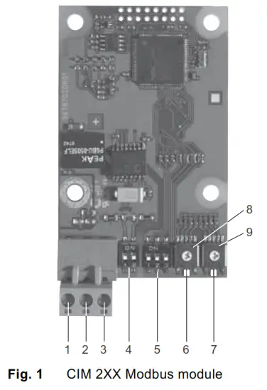
| Pos. | Designation | Description |
| 1 | D1 | Modbus terminal D1 (positive data signal) |
| 2 | DO | Modbus terminal DO (negative data signal) |
| 3 | Common/GND | Modbus terminal Common/GND |
| 4 | SW1 /SW2 | On/off switches for termination resistor |
| 5 | SW3/SW4/SW5 | Switches for selection of Modbus parity and transmission speed |
| 6 | LED1 | Red/green status LED for Modbus communication |
| 7 | LED2 | Red/green status LED for internal communication between the CIM 2XX and the Grundfos product |
| 8 | SW6 | Hex switch for setting the Modbus address (four most significant bits) |
| 9 | SW7 | Hex switch for setting the Modbus address (four least significant bits) |
Installation
![]() Warning
Warning
The CIM 2XX must only be connected to SELV or SELV-E circuits.
3.1 Connecting the Modbus
A screened, twisted-pair cable must be used. The cable screen must be connected to protective earth at both ends.
Recommended connection
| Modbus terminal | Colour code | Data signal |
| D1 | Yellow | Positive |
| D0 | Brown | Negative |
| Common/GND | Grey | Common/GND |
Fitting the cable
Procedure:
See fig. 3.
- Connect the yellow conductor(s) to terminal D1 (pos. 1).
- Connect the brown conductor(s) to terminal D0 (pos. 2).
- Connect the grey conductor(s) to terminal Common/GND (pos. 3).
- Connect the cable screens to earth via the earth clamp (pos. 4).
Note
It is important to connect the screen to earth through the earth clamp and to connect the screen to earth in all units connected to the bus line.
Maximum cable length, see section 3.3 Termination resistor.
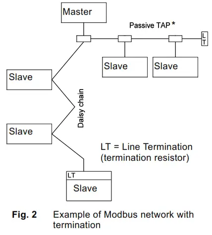
* Hardware unit enabling connection to the Modbus network.
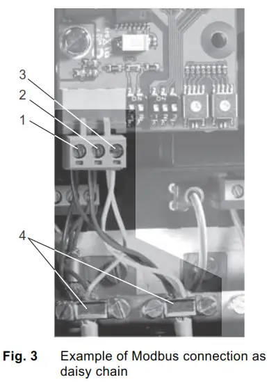
| Pos. | Description |
| 1 | Modbus terminal D1 |
| 2 | Modbus terminal D0 |
| 3 | Modbus terminal Common/GND |
| 4 | Earth clamp |
3.2 Setting the Modbus address
The CIM 2XX Modbus module has two hexadecimal rotary switches for setting the Modbus address.
The two switches are used for setting the four most significant bits (SW6) and the four least significant bits (SW7), respectively. See fig. 4.

The table below shows examples of Modbus address settings.
For a complete overview of Modbus addresses, see the table on page 10.
Note
The Modbus address must be set decimally from 1 to 247.
| Modbus address | SW6 | SW7 |
| 80 | 0 | 8 |
| 20 | 1 | 4 |
| 31 | 1 | F |
| 247 | F | 7 |
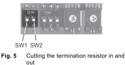
3.3 Termination resistor
The termination resistor is fitted on the CIM 2XX Modbus module and has a value of 150 Ω.
The CIM 2XX has a DIP switch with two switches (SW1 and SW2) for cutting the termination resistor in and out. Figure 5 shows the DIP switches in cut-out state.
DIP switch settings
| Status | SW1 | SW2 |
| Cut-in | ON | ON |
| Cut-out | OFF | OFF |
| ON | OFF | |
| OFF | ON | |
| Cable length | ||
| bits/s | Maximum cable length | |
| Terminated cable | Unterminated cable | |
| [m/ft] | [m/ft] | |
| 1200-9600 | 1200/4000 | 1200/4000 |
| 19200 | 1200/4000 | 500/1700 |
| 38400 | 1200/4000 | 250/800 |
Note
To ensure a stable and reliable communication, it is important that only the termination resistor of the first and last unit in the Modbus network is cut in. See fig. 2.
3.3 Termination resistor
The parity can be set either manually by using SW3 or via software-defined settings.
Manual setting of parity and stop bit
Default byte format (11 bits):
- 1 start bit
- 8 data bits (least significant bit sent first)
- 1 parity bit (even parity)
- 1 stop bit.
See fig. 6.

DIP switch settings
| Parity | SW3 |
| Even parity, 1 stop bit [default] | OFF |
| No parity, 2 stop bits | ON |
Software-defined parity and stop bit
When SW4 and SW5 are set to “software-defined”, the value in holding registers at addresses 00009 and 00010 will override the setting of SW3. See figs 6 and 7.
| Software-defined parity | Set register value 00009 |
| No parity [default] | 0 |
| Even parity | 1 |
| Odd parity | 2 |
| Software-defined stop bit | Set register value 00010 |
| 1 stop bit [default] | 1 |
| 2 stop bits | 2 |
Note
Before the parity and stop bit can be set via software-defined settings, SW4 and SW5 must be set to ON.
3.5 Setting the Modbus transmission speed
The transmission speed must be set correctly before the CIM 2XX Modbus module is ready to communicate with the Modbus network. See fig. 7.

DIP switch settings
| Transmission speed [bits/s] | SW4 | SW5 |
| 9600 | OFF | ON |
| 19200 | OFF | OFF |
| 38400 | ON | OFF |
| Software-defined | ON | ON |
Software-defined
When SW4 and SW5 are set to “software-defined”, writing a value to the holding register at address 00004 will set a new transmission speed.
Use the following values for software-defined transmission speeds:
| Software-defined transmission speed | Set register value 00004 |
| 1200 bits/s | 0 |
| 2400 bits/s | 1 |
| 4800 bits/s | 2 |
| 9600 bits/s | 3 |
| 19200 bits/s | 4 |
| 38400 bits/s | 5 |
Note
When software-defined transmission speed is enabled (ON), software-defined parity and stop bit are also enabled.
LEDs
The CIM 2XX Modbus module has two LEDs. See fig. 1.
- Red/green status LED (LED1) for Modbus communication
- Red/green status LED (LED2) for internal communication between the CIM 2XX and the Grundfos product.
LED1
| Status | Description |
| Off. | No Modbus communication. |
| Flashing green. | Modbus communication active. |
| Flashing red. | Fault in the Modbus communication. |
| Permanently red. | Fault in the CIM 2XX Modbus configuration. |
LED2
| Status | Description |
| Off. | The CIM 2XX has been switched off. |
| Flashing red. | No internal communication between the CIM 2XX and the Grundfos product. |
| Permanently red. | The CIM 2XX does not support the Grundfos product connected. |
| Permanently green. | Internal communication between the CIM 2XX and the Grundfos product is OK. |
Note
During start-up, there may be a delay of up to 5 seconds before the LED2 status is updated.
Fault finding
Faults in a CIM 2XX Modbus module can be detected by observing the status of the two communication LEDs.
See the table below.
CIM 2XX fitted in a Grundfos product
| Fault (LED status) | Possible cause | Remedy | ||
| 1. | Both LEDs (LED1 and LED2) remain off when the power supply is connected. | a) | The CIM 2XX is fitted incorrectly in the Grundfos product. | Check that the CIM 2XX is fitted/ connected correctly. |
| b) | The CIM 2XX is defective. | Replace the CIM 2XX. | ||
| 2. | The LED for internal communication (LED2) is flashing red. | a) | No internal communication between the CIM 2XX and the Grundfos product. | Check that the CIM 2XX is fitted correctly in the Grundfos product. |
| 3. | The LED for internal communication (LED2) is permanently red. | a) | The CIM 2XX does not support the Grundfos product connected. | Contact the nearest Grundfos company. |
| 4. | The Modbus LED (LED1) is permanently red. | a) | Fault in the CIM 2XX Modbus configuration. | • Check the transmission speed (switches SW4 and SW5). If the switches are set to “software-defined”, an invalid value may have been set via Modbus. Try one of the preselected transmission speeds, e.g. 19200 bits/s. • Check that the Modbus address (switches SW6 and SW7) has a valid value [1-247]. |
| 5. | The Modbus LED (LED1) is flashing red. | a) | Fault in the Modbus communication (fault in parity or cyclic redundancy check). | • Check the transmission speed (switches SW4 and SW5). See section 3.5. • Check the parity setting (switch SW3). See section 3.4. • Check the cable connection between the CIM 2XX and the Modbus network. • Check the termination resistor settings (switches SW1 and SW2). See section 3.3. |
CIM 2XX fitted in the CIU 2XX
| Fault (LED status) | Possible cause | Remedy | ||
| 1. | Both LEDs (LED1 and LED2) remain off when the power supply is connected. | a) | The CIU 2XX is defective. | Replace the CIU 2XX. |
| 2. | The LED for internal communication (LED2) is flashing red. | a) | No internal communication between the CIU 2)0( and the Grundfos product. | • Check the cable connection between the Grundfos product and the CIU 2XX. • Check that the individual conductors have been fitted correctly. • Check the power supply to the Grundfos product. |
| 3. | The LED for internal communication (LED2) is permanently red. | a) | The CIU 2XX does not support the Grundfos product connected. | Contact the nearest Grundfos company. |
| 4. | The Modbus LED (LED1) is permanently red. | a) | Fault in the CIM 2XX Modbus configuration. | • Check the transmission speed (switches SW4 and SW5). If the switches are set to “software-defined”, an invalid value may have been set via Modbus. Try one of the preselected transmission speeds, e.g. 19200 bits/s. • Check that the Modbus address (switches SW6 and SW7) has a valid value [1-247]. |
| 5. | The Modbus LED (LED1) is flashing red. | a) | Fault in the Modbus communication (fault in parity or cyclic redundancy check). | • Check the transmission speed (switches SW4 and SW5). See section 3.5. • Check the parity setting (switch SW3). See section 3.4. • Check the cable connection between the CIM 2XX and the Modbus network. • Check the termination resistor settings (switches SW1 and SW2). See section 3.3. |
Technical data
| Transceiver | RS-485 |
| Cable | Screened, twisted-pair Min. 0.25 mm2 Min. 23 AWG |
| Maximum cable length | 1200 m 4000 ft |
| Transmission speed | 1200-38400 bits/s |
| Maximum number of Mod bus units per segment | 32 |
| Protocol | Mod bus RTU |
| Supply voltage | 5 VDC ± 5 %, Imax. 200 mA |
| Storage temperature | -25 °C to +70 °C -13 °F to +158 °F |
Service
7.1 Service documentation
Service documentation is available on www.grundfos.com > International website >
Grundfos Product Center > Service.
If you have any questions, please contact the nearest Grundfos company or service workshop.
Disposal
This product or parts of it must be disposed of in an environmentally sound way:
- Use the public or private waste collection service.
- If this is not possible, contact the nearest
Grundfos company or service workshop.
![]() The crossed-out wheelie bin symbol on a product means that it must be disposed of separately from household waste. When a product marked with this symbol reaches its end of life, take it to a collection point designated by the local waste disposal authorities. The separate collection and recycling of such products will help protect the environment and human health.
The crossed-out wheelie bin symbol on a product means that it must be disposed of separately from household waste. When a product marked with this symbol reaches its end of life, take it to a collection point designated by the local waste disposal authorities. The separate collection and recycling of such products will help protect the environment and human health.
Appendix
Modbus addresses
| Modbus Address | SW 6 | SW 7 |
| 1 | 0 | 1 |
| 2 | 0 | 2 |
| 3 | 0 | 3 |
| 4 | 0 | 4 |
| 5 | 0 | 5 |
| 6 | 0 | 6 |
| 7 | 0 | 7 |
| 8 | 0 | 8 |
| 9 | 0 | 9 |
| 10 | 0 | A |
| 11 | 0 | B |
| 12 | 0 | C |
| 13 | 0 | D |
| 14 | 0 | E |
| 15 | 0 | F |
| 16 | 1 | 0 |
| 17 | 1 | 1 |
| 18 | 1 | 2 |
| 19 | 1 | 3 |
| 20 | 1 | 4 |
| 21 | 1 | 5 |
| 22 | 1 | 6 |
| 23 | 1 | 7 |
| 24 | 1 | 8 |
| 25 | 1 | 9 |
| 26 | 1 | A |
| 27 | 1 | B |
| 28 | 1 | C |
| 29 | 1 | D |
| 30 | 1 | E |
| 31 | 1 | F |
| 32 | 2 | 0 |
| 33 | 2 | 1 |
| 34 | 2 | 2 |
| 35 | 2 | 3 |
| 36 | 2 | 4 |
| 37 | 2 | 5 |
| 38 | 2 | 6 |
| 39 | 2 | 7 |
| 40 | 2 | 8 |
| 41 | 2 | 9 |
| 42 | 2 | A |
| 43 | 2 | B |
| 44 | 2 | C |
| 45 | 2 | D |
| 46 | 2 | E |
| 47 | 2 | F |
| 48 | 3 | 0 |
| 49 | 3 | 1 |
| 50 | 3 | 2 |
| 51 | 3 | 3 |
| 52 | 3 | 4 |
| 53 | 3 | 5 |
| 54 | 3 | 6 |
| 55 | 3 | 7 |
| 56 | 3 | 8 |
| 57 | 3 | 9 |
| 58 | 3 | A |
| 59 | 3 | B |
| 60 | 3 | C |
| 61 | 3 | D |
| 62 | 3 | E |
| 63 | 3 | F |
| 64 | 4 | 0 |
| 65 | 4 | 1 |
| 66 | 4 | 2 |
| 67 | 4 | 3 |
| 68 | 4 | 4 |
| 69 | 4 | 5 |
| 70 | 4 | 6 |
| 71 | 4 | 7 |
| 72 | 4 | 8 |
| 73 | 4 | 9 |
| 74 | 4 | A |
| 75 | 4 | B |
| 76 | 4 | C |
| 77 | 4 | D |
| 78 | 4 | E |
| 79 | 4 | F |
| 80 | 5 | 0 |
| 81 | 5 | 1 |
| 82 | 5 | 2 |
| 83 | 5 | 3 |
| 84 | 5 | 4 |
| 85 | 5 | 5 |
| 86 | 5 | 6 |
| 87 | 5 | 7 |
| 88 | 5 | 8 |
| 89 | 5 | 9 |
| 90 | 5 | A |
| 91 | 5 | B |
| 92 | 5 | C |
| 93 | 5 | D |
| 94 | 5 | E |
| 95 | 5 | F |
| 96 | 6 | 0 |
| 97 | 6 | 1 |
| 98 | 6 | 2 |
| 99 | 6 | 3 |
| 100 | 6 | 4 |
| 101 | 6 | 5 |
| 102 | 6 | 6 |
| 103 | 6 | 7 |
| 104 | 6 | 8 |
| 105 | 6 | 9 |
| 106 | 6 | A |
| 107 | 6 | B |
| 108 | 6 | C |
| 109 | 6 | D |
| 110 | 6 | E |
| 111 | 6 | F |
| 112 | 7 | 0 |
| 113 | 7 | 1 |
| 114 | 7 | 2 |
| 115 | 7 | 3 |
| 116 | 7 | 4 |
| 117 | 7 | 5 |
| 118 | 7 | 6 |
| 119 | 7 | 7 |
| 120 | 7 | 8 |
| 121 | 7 | 9 |
| 122 | 7 | A |
| 123 | 7 | B |
| 124 | 7 | C |
| 125 | 7 | D |
| 126 | 7 | E |
| 127 | 7 | F |
| 128 | 8 | 0 |
| 129 | 8 | 1 |
| 130 | 8 | 2 |
| 131 | 8 | 3 |
| 132 | 8 | 4 |
| 133 | 8 | 5 |
| 134 | 8 | 6 |
| 135 | 8 | 7 |
| 136 | 8 | 8 |
| 137 | 8 | 9 |
| 138 | 8 | A |
| 139 | 8 | B |
| 140 | 8 | C |
| 141 | 8 | D |
| 142 | 8 | E |
| 143 | 8 | F |
| 144 | 9 | 0 |
| 145 | 9 | 1 |
| 146 | 9 | 2 |
| 147 | 9 | 3 |
| 148 | 9 | 4 |
| 149 | 9 | 5 |
| 150 | 9 | 6 |
| 151 | 9 | 7 |
| 152 | 9 | 8 |
| 153 | 9 | 9 |
| 154 | 9 | A |
| 155 | 9 | B |
| 156 | 9 | C |
| 157 | 9 | D |
| 158 | 9 | E |
| 159 | 9 | F |
| 160 | A | 0 |
| 161 | A | 1 |
| 162 | A | 2 |
| 163 | A | 3 |
| 164 | A | 4 |
| 165 | A | 5 |
| 166 | A | 6 |
| 167 | A | 7 |
| 168 | A | 8 |
| 169 | A | 9 |
| 170 | A | A |
| 171 | A | B |
| 172 | A | C |
| 173 | A | D |
| 174 | A | E |
| 175 | B | F |
| 176 | B | 0 |
| 177 | B | 1 |
| 178 | B | 2 |
| 179 | B | 3 |
| 180 | B | 4 |
| 181 | B | 5 |
| 182 | B | 6 |
| 183 | B | 7 |
| 184 | B | 8 |
| 185 | B | 9 |
| 186 | B | A |
| 187 | B | B |
| 188 | B | C |
| 189 | B | D |
| 190 | B | E |
| 191 | B | F |
| 192 | C | 0 |
| 193 | C | 1 |
| 194 | C | 2 |
| 195 | C | 3 |
| 196 | C | 4 |
| 197 | C | 5 |
| 198 | C | 6 |
| 199 | C | 7 |
| 200 | C | 8 |
| 201 | C | 9 |
| 202 | C | A |
| 203 | C | B |
| 204 | C | C |
| 205 | C | D |
| 206 | C | E |
| 207 | C | F |
| 208 | D | 0 |
| 209 | D | 1 |
| 210 | D | 2 |
| 211 | D | 3 |
| 212 | D | 4 |
| 213 | D | 5 |
| 214 | D | 6 |
| 215 | D | 7 |
| 216 | D | 8 |
| 217 | D | 9 |
| 218 | D | A |
| 219 | D | B |
| 220 | D | C |
| 221 | D | D |
| 222 | D | E |
| 223 | D | F |
| 224 | E | 0 |
| 225 | E | 1 |
| 226 | E | 2 |
| 227 | E | 3 |
| 228 | E | 4 |
| 229 | E | 5 |
| 230 | E | 6 |
| 231 | E | 7 |
| 232 | E | 8 |
| 233 | E | 9 |
| 234 | E | A |
| 235 | E | B |
| 236 | E | C |
| 237 | E | D |
| 238 | E | E |
| 239 | E | F |
| 240 | F | 0 |
| 241 | F | 1 |
| 242 | F | 2 |
| 243 | F | 3 |
| 244 | F | 4 |
| 245 | F | 5 |
| 246 | F | 6 |
| 247 | F | 7 |
Caution
It is very important to ensure that two devices do not have the same address on the network. If two devices have the same address, the result will be an abnormal behavior of the whole serial bus.
Declaration of conformity
EU declaration of conformity
We, Grundfos, declare under our sole responsibility that the products CIM 05x, CIM 1xx, CIM 2xx, CIM 3xx, CIU, to which the declaration below relates, are in conformity with the Council Directives listed below on the approximation of the laws of the EU member states.
- Low Voltage Directive (2014/35/EU).
Standard used:
EN 61010-1:2010 - EMC Directive (2014/30/EU).
Standard used:
EN 61326-1:2013 - RoHS 2 Directive (2011/65/EU and 2015/863/EU).
This EU declaration of conformity is only valid when published as part of the Grundfos installation and operating instructions (publication numbers 96846334 1119, 96846335 1119, 96846336 1119, 96846337
0516, 97532865 1119, 98353942 0516).
Bjerringbro, 1/11/2019

Anne Katrine Windfall
Senior Manager
Grundfos Holding A/S
Poul Due Jensen’s Vej 7
8850 Bjerringbro, Denmark
Person authorised to compile the technical file and empowered to sign the EU declaration of conformity.
Grundfos companies
| Canada GRUNDFOS Canada Inc. 2941 Brighton Road Oakville, Ontario L6H 6C9 Phone: +1-905 829 9533 Telefax: +1-905 829 9512 |
Malaysia GRUNDFOS Pumps Sdn. Bhd. 7 Jalan Peguam U1/25 Glenmarie Industrial Park 40150 Shah Alam Selangor Phone: +60-3-5569 2922 Telefax: +60-3-5569 2866 |
New Zealand GRUNDFOS Pumps NZ Ltd. 17 Beatrice Tinsley Crescent North Harbour Industrial Estate Albany, Auckland Phone: +64-9-415 3240 Telefax: +64-9-415 3250 |
| United Kingdom GRUNDFOS Pumps Ltd. Grovebury Road Leighton Buzzard/Beds. LU7 4TL Phone: +44-1525-850000 Telefax: +44-1525-850011 |
U.S.A. GRUNDFOS Pumps Corporation 9300 Loiret Blvd. Lenexa, Kansas 66219 Phone: +1-913-227-3400 Telefax: +1-913-227-3500 |
Thailand GRUNDFOS (Thailand) Ltd. 92 Chaloem Phakia Rama 9 Road, Dokmai, Pravej, Bangkok 10250 Phone: +66-2-725 8999 Telefax: +66-2-725 8998 |
![]() 96846335 05.2020
96846335 05.2020
ECM: 1286110
www.grundfos.com
Trademarks displayed in this material, including but not limited to Grundfos, the Grundfos logo and “be
think innovate” are registered trademarks owned by The Grundfos Group. All rights reserved.
© 2020 Grundfos Holding A/S, all rights reserved.
Documents / Resources
 |
Grundfos CIM 2XX Modbus Module [pdf] Instructions CIM 2XX Modbus Module, CIM 2XX, Modbus Module, Module |