Fronius RI FB PRO Setting The Bus Module
 Specifications
- Vendor ID: 0000 02C1hex (705dez)
- Product Code: 0000 0320hex (800dez)
- Device Name: Fronius FB Pro CANopen
Product Usage Instructions
Setting up the Node Address of the Bus Module
The node address of the bus module can be set using the DIP switch on the interface:
- Range: 1 to 63
- DIP Switch Positions:
- 1: OFF OFF OFF OFF OFF ON
- 2: OFF OFF OFF OFF ON OFF
- 3: OFF OFF OFF OFF ON ON…
- 62: ON ON ON ON ON OFF
- 63: ON ON ON ON ON ON
Setting Process Data Width of the Bus Module
- The process data width of the bus module can be adjusted as per the requirements outlined in the manual.
Input and Output Signals
The product utilizes different data types for signals:
- UINT16 (Unsigned Integer): Range from 0 to 65535
- SINT16 (Signed Integer): Range from -32768 to 32767
Working Mode Bit Configuration
- The product has specific bits allocated for working mode configurations such as Welding Start, Robot Ready, Gas On, and more. Refer to the provided table for detailed information on each bit’s function.
General
Safety
WARNING!
Danger from incorrect operation and work that is not carried out properly. This can result in serious personal injury and damage to property.
- All the work and functions described in this document must only be carried out by technically trained and qualified personnel.
- Read and understand this document in full.
- Read and understand all safety rules and user documentation for this equip-ment and all system components.
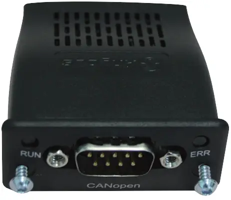
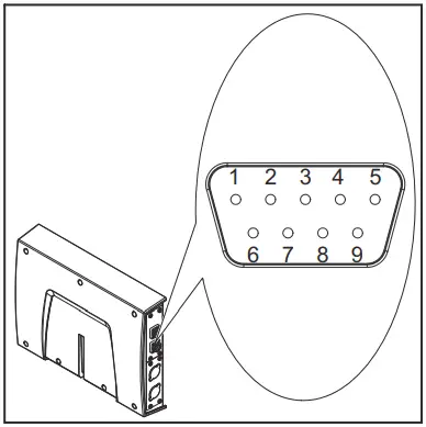
Connections and Indicators
| Pin | Signal |
| 1 | – |
| 2 | CAN_L |
| 3 | CAN_GND |
| 4 | – |
| 5 | CAN_SHD |
| 6 | – |
| 7 | CAN_H |
| 8 | – |
| 9 | – |
| Housing = CAN_SHIELD | |
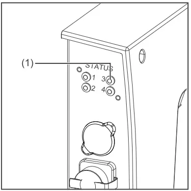
| (1) ERR LED – error |
| Off:
No power or device is in working condition |
| Red, single flash:
Warning limit reached A bus error counter has reached or exceeded the limit for a warning |
| Red, flickering:
LSS service running |
| Red, double flash:
Error control event A „Guard-“ or „Heartbeat“ error has occurred |
| Red:
Bus off (Fatal event) No communication (fatal error) |
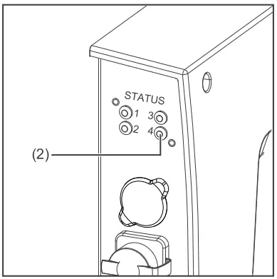
| (2) RUN LED – operation |
| Off:
No supply voltage |
| Green:
Module in ‘operational’ status |
| Green, blinking:
Module in ‘pre-operational’ status |
| Green, one flash:
Module in ‘stopped’ status |
| Green, flickering:
Autobaud Baud rate detection in progress |
| Lights up red:
If the Run LED and Error LED light up red, this indicates a serious event that places the interface in an ex- caption state. Contact the service team |
Network topology:
- Linear bus, bus termination on both ends (121 Ohm), avoid stub cables
Medium and maximum bus length:
- When selecting cable, plug, and terminating resistors, ISO11898-2 and the CANopen recommendation CiA 303 “Cabling and connector pin assignment” must be observed.
Several stations:
- Max. 64 participants
Transmission speed:
- 1MBit/s, 500 kBit/s, 250 kBit/s, 125 kBit/s, 100 kBits/s, 50 kBits/s, 20 kBits/s, 10 kBits/s
Process data width:
- See section Setting the process data width of the bus module on page 28
Configuration Parameters
In some robot control systems, it may be necessary to state the configuration parameters described here so that the bus module can communicate with the robot.
| Parameter | Value | Description |
| Vendor ID | 0000 02C1hex
(705dec) |
Fronius International GmbH |
| Product Code | 0000 0320hex
(800dec) |
Fronius FB Pro CANopen |
| Device name | Fronius-FB-Pro-CANopen |
Setting the Bus Module Node Address
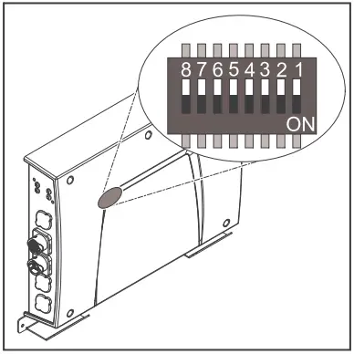
You can set the bus module node address as follows:
- Using the DIP switch in the interface within the range 1 to 63
- All positions are set to the OFF position at the factory. In this case, the IP address must be set on the website of the welding machine
- On the website of the welding machine within the range 1 to 126 (if all positions of the DIP switch are set to the OFF position)
| Example for setting the node address of the bus module using the DIP switch in the interface: | ||||||||
| Dip switch |
Node address |
|||||||
| 8 | 7 | 6 | 5 | 4 | 3 | 2 | 1 | |
| – | – | OFF | OFF | OFF | OFF | OFF | ON | 1 |
| – | – | OFF | OFF | OFF | OFF | ON | OFF | 2 |
| – | – | OFF | OFF | OFF | OFF | ON | ON | 3 |
| – | – | ON | ON | ON | ON | ON | OFF | 62 |
| – | – | ON | ON | ON | ON | ON | ON | 63 |
The node address is set with positions 1 to 6 of the dip switch. The configuration is carried out in binary format. This results in a configuration range of 1 to 63 in decimal format.
Setting the node address on the website of the welding machine:
Note down the IP address of the welding machine used:
- On the welding machine control panel, select “Defaults” select “System”
- On the welding machine control panel, select “Information” Note down the displayed IP address (example: 10.5.72.13)
Access the website of the welding machine in the internet browser: Connect the computer to the network of the welding machine
- Enter the IP address of the welding machine in the search bar of the internet browser and confirm
- Enter the standard user name (admin) and password (admin)
The website of the welding machine is displayed Set the bus module node address:
- On the welding machine website, select the “RI FB PRO/i” tab
- Enter the desired node address for the interface under “Module configuration”
For example: 2
- Select “Set configuration” Select “Restart module”
- The set node address is applied
Set the Process Data Width of the Bus Module
Setting the pro- cess data width of the bus module
- Note down the IP address of the welding machine used:
- On the welding machine control panel, select “Defaults”
- On the welding machine control panel, select “System”
- On the welding machine control panel, select “Information”
- Note down the displayed IP address (example: 10.5.72.13)
Open the website of the welding machine in the internet browser:
- Connect the computer to the network of the welding machine
- Enter the IP address of the welding machine in the search bar of the internet browser and confirm
- Enter the standard user name (admin) and password (admin)
- The website of the welding machine is displayed
Set the process data width of the bus module:
- On the welding machine website, select the “RI FB PRO/i” tab
- Under “Process data”, select the desired process data configuration
- Select “Save”
- The field bus connection is restarted and the configuration is applied
- Input and output signals
Data types
The following data types are used:
- UINT16 (Unsigned Integer)
- The whole number in the range from 0 to 65535
- SINT16 (Signed Integer)
- The whole number ranges from -32768 to 32767
Conversion examples:
- for a positive value (SINT16) e. g. desired wire speed x factor 12.3 m/min x 100 = 1230dec = 04CEhex
- for a negative value (SINT16) e.g. arc correction x factor 6.4 x 10 = -64dec = FFC0hex
Availability of input signals
The input signals listed below are available from firmware V2.0.0 of the RI FB PRO/I onwards.
Input signals (from robot to power source)
|
Address |
Signal |
Activity/data type |
Range |
Factor | Process image | ||||
|
Relative |
Absolu- te | Standard | Economy | ||||||
| WORD | BYTE | BIT |
BIT |
||||||
|
0 |
0 |
0 | 0 | Welding Start | Increa- sing |
ü |
ü |
||
| 1 | 1 | Robot ready | High | ||||||
| 2 | 2 | Working mode Bit 0 | High |
See table Value Range for Working Mode on page 35 |
|||||
| 3 | 3 | Working mode Bit 1 | High | ||||||
| 4 | 4 | Working mode Bit 2 | High | ||||||
| 5 | 5 | Working mode Bit 3 | High | ||||||
| 6 | 6 | Working mode Bit 4 | High | ||||||
| 7 | 7 | — | |||||||
|
1 |
0 | 8 | Gas on | Increa- sing | |||||
| 1 | 9 | Wire forward | Increa- sing | ||||||
| 2 | 10 | Wire backward | Increa- sing | ||||||
| 3 | 11 | Error quit | Increa- sing | ||||||
| 4 | 12 | Touch sensing | High | ||||||
| 5 | 13 | Torch blow out | Increa- sing | ||||||
| 6 | 14 | Processing selection Bit 0 | High | See table Value range Process li- ne selection on page 36 | |||||
|
7 |
15 |
Processing selection Bit 1 |
High |
||||||
|
Address |
Signal |
Activity/data type |
Range |
Factor | Process image | ||||
|
Relative |
Absolu- te | Standard | Economy | ||||||
| WORD | BYTE | BIT |
BIT |
||||||
|
1 |
2 |
0 | 16 | Welding simulation | High |
ü |
ü |
||
|
1 |
17 |
Welding process MIG/MAG: 1)
Synchro pulse on |
High |
||||||
| Welding process WIG: 2)
TAC on |
High |
||||||||
|
2 |
18 |
Welding process WIG: 2)
Cap shaping |
High |
||||||
| 3 | 19 | — | |||||||
| 4 | 20 | — | |||||||
| 5 | 21 | Booster manual | High | ||||||
| 6 | 22 | Wire brake on | High | ||||||
| 7 | 23 | Torchbody Xchange | High | ||||||
|
3 |
0 | 24 | — | ||||||
| 1 | 25 | Teach mode | High | ||||||
| 2 | 26 | — | |||||||
| 3 | 27 | — | |||||||
| 4 | 28 | — | |||||||
| 5 | 29 | Wire since start | Increa- sing | ||||||
| 6 | 30 | Wire sense break | Increa- sing | ||||||
| 7 | 31 | — | |||||||
|
Address |
Signal |
Activity/data type |
Range |
Factor | Process image | ||||
|
Relative |
Absolu- te | Standard | Economy | ||||||
| WORD | BYTE | BIT |
BIT |
||||||
|
2 |
4 |
0 | 32 | TWIN mode Bit 0 | High | See table Value Range for TWIN Mode on page 36 |
ü |
ü |
|
|
1 |
33 |
TWIN mode Bit 1 |
High |
||||||
| 2 | 34 | — | |||||||
| 3 | 35 | — | |||||||
| 4 | 36 | — | |||||||
|
5 |
37 |
Documentation mode |
High |
See table Value Range for Docu- mentation Mode on page 36 | |||||
| 6 | 38 | — | |||||||
| 7 | 39 | — | |||||||
|
5 |
0 | 40 | — | ||||||
| 1 | 41 | — | |||||||
| 2 | 42 | — | |||||||
| 3 | 43 | — | |||||||
| 4 | 44 | — | |||||||
| 5 | 45 | — | |||||||
| 6 | 46 | — | |||||||
| 7 | 47 | Disable process-controlled correction | High | ||||||
|
Address |
Signal |
Activity/data type |
Range |
Factor | Process image | ||||
|
Relative |
Absolu- te | Standard | Economy | ||||||
| WORD | BYTE | BIT |
BIT |
||||||
|
3 |
6 |
0 | 48 | — |
ü |
ü |
|||
| 1 | 49 | — | |||||||
| 2 | 50 | — | |||||||
| 3 | 51 | — | |||||||
| 4 | 52 | — | |||||||
| 5 | 53 | — | |||||||
| 6 | 54 | — | |||||||
| 7 | 55 | — | |||||||
|
7 |
0 | 56 | ExtInput1 => OPT_Output 1 | High | |||||
| 1 | 57 | ExtInput2 => OPT_Output 2 | High | ||||||
| 2 | 58 | ExtInput3 => OPT_Output 3 | High | ||||||
| 3 | 59 | ExtInput4 => OPT_Output 4 | High | ||||||
| 4 | 60 | ExtInput5 => OPT_Output 5 | High | ||||||
| 5 | 61 | ExtInput6 => OPT_Output 6 | High | ||||||
| 6 | 62 | ExtInput7 => OPT_Output 7 | High | ||||||
| 7 | 63 | ExtInput8 => OPT_Output 8 | High | ||||||
| 4 | 8-
9 |
0–7 | 64–79 | Welding characteristic- / Job number | UINT16 | 0 to 1000 | 1 | ü | ü |
|
5 |
10 – 11 |
0-7 |
80-95 |
Welding process MIG/MAG: 1)
Constant Wire:
Wire feed speed command value |
SINT16 |
-327,68 to 327,67 [m/min] |
100 |
ü |
ü |
| Welding process WIG: 2)
Main- / Hotwire current command value |
UINT16 |
0 to 6553,5 [A] |
10 |
||||||
| For job-mode:
Power correction |
SINT16 |
-20,00 to
20,00 [%] |
100 |
||||||
|
Address |
Signal |
Activity/data type |
Range |
Factor | Process image | ||||
|
Relative |
Absolu- te | Standard | Economy | ||||||
| WORD | BYTE | BIT |
BIT |
||||||
|
6 |
12 – 13 |
0-7 |
96-111 |
Welding process MIG/MAG: 1)
Arclength correction |
SINT16 |
-10,0 to
10,0 [Schritte] |
10 |
ü |
ü |
| Welding process
MIG/MAG Standard-Manuel:
Welding voltage |
UINT16 |
0,0 to
6553,5 [V] |
10 |
||||||
| Welding process WIG: 2)
Wire feed speed command value |
SINT16 |
-327,68 to 327,67 [m/min] |
100 |
||||||
| For job-mode:
Arclength correction |
SINT16 |
-10,0 to
10,0 [Schritte] |
10 |
||||||
| Welding process Constant Wire:
Hotwire current |
UINT16 |
0,0 to
6553,5 [A] |
10 |
||||||
|
7 |
14 – 15 |
0-7 |
112-127 |
Welding process MIG/MAG: 1)
Pulse-/dynamic correction |
SINT16 |
-10,0 to
10,0 [steps] |
10 |
ü |
ü |
| Welding process
MIG/MAG Standard-Manuel:
Dynamic |
UINT16 |
0,0 to
10,0 [steps] |
10 |
||||||
| Welding process WIG: 2)
Wire correction |
SINT16 |
-10,0 to
10,0 [steps] |
10 |
||||||
|
8 |
16 – 17 |
0-7 |
128-143 |
Welding process MIG/MAG: 1)
Wire retract correction |
UINT16 |
0,0 to
10,0 [steps] |
10 |
ü |
|
| Welding process WIG: 2)
Wire retract end |
UINT16 |
OFF, 1 to
50 [mm] |
1 |
||||||
|
9 |
18
– 19 |
0-7 |
144-159 |
Welding speed |
UINT16 |
0,0 to
1000,0 [cm/min] |
10 |
ü |
|
|
Address |
Signal |
Activity/data type |
Range |
Factor | Process image | ||||
|
Relative |
Absolu- te | Standard | Economy | ||||||
| WORD | BYTE | BIT |
BIT |
||||||
|
10 |
20 – 21 |
0-7 |
160-175 |
Process controlled correction |
See table Value range for Process controlled correction on page 36 |
ü |
|||
|
11 |
22
– 23 |
0-7 |
176-191 |
Welding process WIG: 2)
Wire positioning start |
ü |
||||
|
12 |
24
– 25 |
0-7 |
192-207 |
— |
ü |
||||
|
13 |
26
– 27 |
0-7 |
208-223 |
— |
ü |
||||
|
14 |
28
– 29 |
0-7 |
224-239 |
— |
ü |
||||
|
15 |
30
– 31 |
0-7 |
240-255 |
Wire forward / backward length |
UINT16 |
OFF / 1 to 65535 [mm] |
1 |
ü |
|
|
16 |
32
– 33 |
0-7 |
256-271 |
Wire sense edge detection |
UINT16 |
OFF / 0,5
to 20,0 [mm] |
10 |
ü |
|
|
17 |
34
– 35 |
0-7 |
272-287 |
— |
ü |
||||
|
18 |
36
– 37 |
0-7 |
288-303 |
— |
ü |
||||
|
19 |
38
– 39 |
0-7 |
304-319 |
Seam number |
UINT16 |
0 to
65535 |
1 |
ü |
|
- MIG/MAG Puls-Synergic, MIG/MAG Standard-Synergic, MIG/MAG Stan-dard-Manuel, MIG/MAG PMC, MIG/MAG, LSC
- WIG cold wire, WIG hotwire
Value Range for Working Mode
| Bit 4 | Bit 3 | Bit 2 | Bit 1 | Bit 0 | Description |
| 0 | 0 | 0 | 0 | 0 | Internal parameter selection |
| 0 | 0 | 0 | 0 | 1 | Special 2-step mode characteristics |
| 0 | 0 | 0 | 1 | 0 | Job mode |
| Bit 4 | Bit 3 | Bit 2 | Bit 1 | Bit 0 | Description |
| 0 | 1 | 0 | 0 | 0 | 2-step mode characteristics |
| 0 | 1 | 0 | 0 | 1 | 2-step MIG/MAG standard manual |
| 1 | 0 | 0 | 0 | 0 | Idle Mode |
| 1 | 0 | 0 | 0 | 1 | Stop coolant pump |
| 1 | 1 | 0 | 0 | 1 | R/L-Measurement |
Value Range for Documentation Mode
| Bit 0 | Description |
| 0 | Seam number of welding machine (internal) |
| 1 | Seam number of robots (Word 19) |
The value range for Process control- led correction
|
Process |
Signal |
Activity/data type |
Value range configuration range |
Unit |
Factor |
|
PMC |
Arc length stabilizer |
SINT16 |
-327.8 to +327.7
0.0 to +5.0 |
Volts |
10 |
The value range for process-dependent correction
|
Process |
Signal |
Activity/data type |
Value range configuration range |
Unit |
Factor |
|
PMC |
Arc length stabilizer |
SINT16 |
-327.8 to +327.7
0.0 to +5.0 |
Volts |
10 |
Value range for process-dependent correction
Value range Pro- cess line selection
| Bit 1 | Bit 0 | Description |
| 0 | 0 | Process line 1 (default) |
| 0 | 1 | Process line 2 |
| 1 | 0 | Process line 3 |
| 1 | 1 | Reserved |
Value range for process line selection
Value Range for TWIN Mode
| Bit 1 | Bit 0 | Description |
| 0 | 0 | TWIN Single mode |
| 0 | 1 | TWIN Lead mode |
| 1 | 0 | TWIN Trail mode |
| 1 | 1 | Reserved |
Value range for TWIN mode
Availability of the output signals
The output signals listed below are available from firmware V2.0.0 of the RI FB PRO/i onwards.
Output Signals (from Power Source to Robot)
|
Address |
Signal |
Activity / data type |
Range |
Factor |
Process image | ||||
| relative | absolute | Standard | Economy | ||||||
| WORD | BYTE | BIT |
BIT |
||||||
|
0 |
0 |
0 | 0 | Heartbeat Powersource | High/Low | 1 Hz |
ü |
ü |
|
| 1 | 1 | Power source ready | High | ||||||
| 2 | 2 | Warning | High | ||||||
| 3 | 3 | Process active | High | ||||||
| 4 | 4 | Current flow | High | ||||||
| 5 | 5 | Arc stable- / touch signal | High | ||||||
| 6 | 6 | Main current signal | High | ||||||
| 7 | 7 | Touch signal | High | ||||||
|
1 |
0 |
8 |
Collision box active |
High |
0 = collision- on or cable break | ||||
| 1 | 9 | Robot Motion Release | High | ||||||
| 2 | 10 | Wire stick workpiece | High | ||||||
| 3 | 11 | — | |||||||
| 4 | 12 | Short circuit contact tip | High | ||||||
| 5 | 13 | Parameter selection eternally | High | ||||||
| 6 | 14 | Characteristic number valid | High | ||||||
| 7 | 15 | Torch body gripped | High | ||||||
|
Address |
Signal |
Activity / data type |
Range |
Factor |
Process image | ||||
| relative | absolute | Standard | Economy | ||||||
| WORD | BYTE | BIT |
BIT |
||||||
|
1 |
2 |
0 | 16 | Command value out of range | High |
ü |
ü |
||
| 1 | 17 | Correction out of range | High | ||||||
| 2 | 18 | — | |||||||
| 3 | 19 | Limitsignal | High | ||||||
| 4 | 20 | — | |||||||
| 5 | 21 | — | |||||||
| 6 | 22 | Main supply status | Low | ||||||
| 7 | 23 | — | |||||||
|
3 |
0 | 24 | Sensor status 1 | High |
See table Assign- ment of Sensor Sta- uses 1–4 on page 40 |
||||
| 1 | 25 | Sensor status 2 | High | ||||||
| 2 | 26 | Sensor status 3 | High | ||||||
| 3 | 27 | Sensor status 4 | High | ||||||
| 4 | 28 | — | |||||||
| 5 | 29 | — | |||||||
| 6 | 30 | — | |||||||
| 7 | 31 | — | |||||||
|
2 |
4 |
0 | 32 | — |
ü |
ü |
|||
| 1 | 33 | — | |||||||
| 2 | 34 | — | |||||||
| 3 | 35 | Safety status Bit 0 | High | See table Value ran- ge Safety status on page 41 | |||||
| 4 | 36 | Safety status Bit 1 | High | ||||||
| 5 | 37 | — | |||||||
| 6 | 38 | Notification | High | ||||||
| 7 | 39 | System not ready | High | ||||||
|
5 |
0 | 40 | — | ||||||
| 1 | 41 | — | |||||||
| 2 | 42 | — | |||||||
| 3 | 43 | — | |||||||
| 4 | 44 | — | |||||||
| 5 | 45 | — | |||||||
| 6 | 46 | — | |||||||
| 7 | 47 | — | |||||||
|
Address |
Signal |
Activity / data type |
Range |
Factor |
Process image | ||||
| relative | absolute | Standard | Economy | ||||||
| WORD | BYTE | BIT |
BIT |
||||||
|
3 |
6 |
0 | 48 | Process Bit 0 | High |
See table Value Range for Process Bit on page 41 |
ü |
ü |
|
| 1 | 49 | Process Bit 1 | High | ||||||
| 2 | 50 | Process Bit 2 | High | ||||||
| 3 | 51 | Process Bit 3 | High | ||||||
| 4 | 52 | Process Bit 4 | High | ||||||
| 5 | 53 | — | |||||||
| 6 | 54 | Touch signal gas nozzle | High | ||||||
| 7 | 55 | TWIN synchronization active | High | ||||||
|
7 |
0 | 56 | ExtOutput1 <= OPT_In- put1 | High | |||||
| 1 | 57 | ExtOutput2 <= OPT_In- put2 | High | ||||||
| 2 | 58 | ExtOutput3 <= OPT_In- put3 | High | ||||||
| 3 | 59 | ExtOutput4 <= OPT_In- put4 | High | ||||||
| 4 | 60 | ExtOutput5 <= OPT_In- put5 | High | ||||||
| 5 | 61 | ExtOutput6 <= OPT_In- put6 | High | ||||||
| 6 | 62 | ExtOutput7 <= OPT_In- put7 | High | ||||||
| 7 | 63 | ExtOutput8 <= OPT_In- put8 | High | ||||||
| 4 | 8-
9 |
0-7 | 64-79 | Welding voltage | UINT16 | 0.0 to
655.35 [V] |
100 | ü | ü |
|
5 |
10
– 11 |
0-7 |
80-95 |
Welding current |
UINT16 |
0.0 to 6553.5 [A] |
10 |
ü |
ü |
|
6 |
12
– 13 |
0-7 |
96-111 |
Wire feed speed |
SINT16 |
-327.68 to
327.67 [m/ min] |
100 |
ü |
ü |
|
7 |
14
– 15 |
0-7 |
112-127 |
Actual real value for seam tracking |
UINT16 |
0 to
6.5535 |
10000 |
ü |
ü |
|
8 |
16
– 17 |
0-7 |
128-143 |
Error number |
UINT16 |
0 to
65535 |
1 |
ü |
|
|
9 |
18
– 19 |
0-7 |
144-159 |
Warning number |
UINT16 |
0 to
65535 |
1 |
ü |
|
|
Address |
Signal |
Activity / data type |
Range |
Factor |
Process image | ||||
| relative | absolute | Standard | Economy | ||||||
| WORD | BYTE | BIT |
BIT |
||||||
|
10 |
20
– 21 |
0-7 |
160-175 |
Motor current M1 |
SINT16 |
-327.68 to
327.67 [A] |
100 |
ü |
|
|
11 |
22
– 23 |
0-7 |
176-191 |
Motor current M2 |
SINT16 |
-327.68 to
327.67 [A] |
100 |
ü |
|
|
12 |
24
– 25 |
0-7 |
192-207 |
Motor current M3 |
SINT16 |
-327.68 to
327.67 [A] |
100 |
ü |
|
|
13 |
26
– 27 |
0-7 |
208-223 |
— |
ü |
||||
|
14 |
28
– 29 |
0-7 |
224-239 |
— |
ü |
||||
|
15 |
30
– 31 |
0-7 |
240-255 |
— |
ü |
||||
|
16 |
32
– 33 |
0-7 |
256-271 |
Wire position |
SINT16 |
-327.68 to
327.67 [mm] |
100 |
ü |
|
|
17 |
34
– 35 |
0-7 |
272-287 |
— |
ü |
||||
|
18 |
36
– 37 |
0-7 |
288-303 |
— |
ü |
||||
|
19 |
38
– 39 |
0-7 |
304-319 |
— |
ü |
||||
Assignment of Sensor Statuses 1–4
| Signal | Description |
| Sensor status 1 | OPT/i WF R wire end (4,100,869) |
| Sensor status 2 | OPT/i WF R wire drum (4,100,879) |
| Sensor status 3 | OPT/i WF R ring sensor (4,100,878) |
| Sensor status 4 | Wire buffer set CMT TPS/i (4,001,763) |
Value range Safety status
| Bit 1 | Bit 0 | Description |
| 0 | 0 | Reserve |
| 0 | 1 | Hold |
| 1 | 0 | Stop |
| 1 | 1 | Not installed / active
|
Value range Safety status
Value Range for Process Bit
| Bit 4 | Bit 3 | Bit 2 | Bit 1 | Bit 0 | Description |
| 0 | 0 | 0 | 0 | 0 | No internal parameter selection or process |
| 0 | 0 | 0 | 0 | 1 | MIG/MAG pulse synergic |
| 0 | 0 | 0 | 1 | 0 | MIG/MAG standard synergic |
| 0 | 0 | 0 | 1 | 1 | MIG/MAG PMC |
| 0 | 0 | 1 | 0 | 0 | MIG/MAG LSC |
| 0 | 0 | 1 | 0 | 1 | MIG/MAG standard manual |
| 0 | 0 | 1 | 1 | 0 | Electrode |
| 0 | 0 | 1 | 1 | 1 | TIG |
| 0 | 1 | 0 | 0 | 0 | CMT |
| 0 | 1 | 0 | 0 | 1 | Constantine |
| 0 | 1 | 0 | 1 | 0 | ColdWire |
| 0 | 1 | 0 | 1 | 1 | DynamicWire |
Value Range for Process Bit
| Bit 1 | Bit 0 | Description |
| 0 | 0 | Inactive |
| 0 | 1 | Idle |
| 1 | 0 | Finished |
| 1 | 1 | Error |
Value Range for Function Status

- spareparts.fronius.com
- At www.fronius.com/contact you will find the contact details of all Fronius subsidiaries and Sales & Service Partners.
Frequently Asked Questions
Q: How many stations can be connected to the bus module?
A: The maximum number of stations that can be connected is 64 participants.
Q: What should I do if the LED indicators show specific colors?
A: Different LED colors indicate various system statuses. For example, a red LED could signify a critical error or communication failure. Refer to the manual for detailed troubleshooting steps.
Documents / Resources
 |
Fronius RI FB PRO Setting The Bus Module [pdf] Instruction Manual 42, 0410, 2656, RI FB PRO Setting The Bus Module, RI FB PRO, Setting The Bus Module, Bus Module, Module |


