![]()
 REV.: 20220114
Guide # 89681
ADDENDUM – SUGGESTED WIRING CONFIGURATION
REGULAR INSTALLATION
2004 Regular Key and Alarm Systems
 Vehicle functions supported in this diagram (functional if equipped)
| Thunderbird | VEHICLE |
| FORD | |
| 2002-2005 | YEARS |
| 1 | 2KEY Programming |
| 2 | 1KEY Programming (Dcryptor) |
| • | Transponder Bypass |

To add the firmware version and the options, use the FLASH LINK UPDATER or FLASH LINK MOBILE tool, sold separately.
WIRING CONNECTION

PROGRAMMING PROCEDURE

Make sure to have two valide vehicle key.
 Press and hold the programming button: Insert the 4-Pin (Data-link Connector) connector.
 Release the programming button when the LED is RED.
 If the LED is not solid RED disconnect the 4-Pin connector (Data-Link) and go back to step 1.
 Insert the required remaining connectors.
 Turn the first functlonal key to the ON/RUN position.
Wait 3 seconds.
 Turn the ignition to the OFF position and remove the first key.
 Turn the second functlonal key to the ON/RUN position.
Wait 3 seconds.
PROGRAMMING PROCEDURE
Turn the ignition to the OFF position and remove the second key.
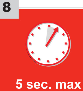 CAUTION The following step must be completed within 5 seconds.
Otherwise disconnect all connectors and go back to step 1.
 Press and hold the programming button until the LED flashes once.
↳ The RED LED will flash once (1x).
Release the programming button.
| AUTOMATIC TRANSMISSION | MANUAL TRANSMISSION |
 Activate the remote starter. Activate the remote starter. |
 Using a jumper wire, apply power (12v) to the vehicle’s ignition1. Using a jumper wire, apply power (12v) to the vehicle’s ignition1. |

The RED LED will flash rapidly ten (10) times.
If the LED is solid RED disconnect the 4-Pin connector (Data Link) and go back to step 1.
 Manual transmission: Remove the jumper.
The module is now programmed.
Use the remote of the remote starter or security system to test all of the supported features to ensure proper programming.
DCRYPTOR PROGRAMMING PROCEDURE
![]() Parts required (not included)
Parts required (not included)
 |
FLASH LINK UPDATER, |
 |
FLASH LINK MANAGER SOFTWARE | PROGRAMME |
 |
Microsoft Windows Computer with Internet connection |
| OR | |
 |
FLASH LINK MOBILE |
 |
FLASH LINK MOBILE |
|
Smartphone Android or iOS with Internet connection (Internet provider charges may apply) |

BEFORE PROGRAMMING SET THE UNIT OPTIONS AND SAVE.

Press and hold the programming button: Insert the 4-Pin (Data-link Connector) connector.
 Release the programming button when the LED is RED.
If the LED is not solid RED disconnect the 4-Pin connector (Data-Link) and go back to step 1.
 Insert the required remaining connectors.
 Press and release the programming button once (1x).
↳ The RED LED will flash once.
 Turn the Ignition to the ON/RUN position.
↳ WAITthe RED LED will turn OFF.
↳ The YELLOW LED will turn on.
 Turn the Ignition to the OFF position.
↳ WAIT the YELLOW LED will turn OFF.
↳ the RED LED will turn ON.
 Turn the Ignition to the ON/RUN position.
↳ The RED and YELLOW LEDs will alternate.
PROGRAMMING PROCEDURE

Turn the Ignition to the ON/RUN position.
↳ WAIT the RED LED will turn OFF.
↳ The YELLOW LED will turn on. 
Turn the Ignition to the OFF position.
↳ WAITthe YELLOW LED wil turn OFF.
↳ the RED LED will turn ON. 
Turn the Ignition to the ON/RUN position.
↳ The RED and YELLOW LEDs will alternate. 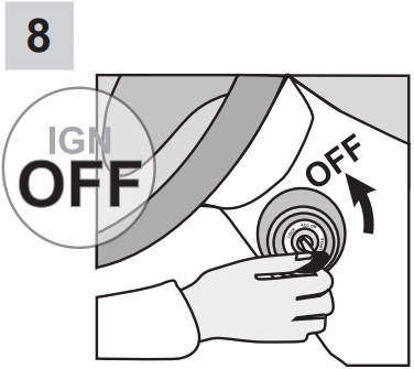 Turn the Ignition to the OFF position.
  Disconnect all connectors.
Use the tool: FLASH LINK UPDATER or FLASH LINK MOBILE to visit the DCryptor menu.
*Parts required (not included)  Reconnect the 4-Pin (Data-Link) connector and after, al the remaining connector.
The module is now programmed.
 REMOTE STARTER
Test the remote starter. Remote start the vehicle.
![]()
 www.fortinbypass.com
Module label
Notice: Updated Firmware and Installation Guides
Updated firmware and installation guides are posted on our web site on a regular basis. We recommend that you update this module to the latest fi rmware and download the latest installation guide(s) prior to the installation of this product.
WARNING
The information on this sheet is provided on an (as is) basis with no representation or warranty of accuracy whatsoever. It is the sole responsibility of the installer to check and verify any circuit before connecting to it. Only a computer safe logic probe or digital multimeter should be used. FORTIN ELECTRONIC SYSTEMS assumes absolutely no liability or responsibility whatsoever pertaining to the accuracy or currency of the information supplied. The installation in every case is the sole responsibility of the installer performing the work and FORTIN ELECTRONIC SYSTEMS assumes no liability or responsibility whatsoever resulting from any type of installation, whether performed properly, improperly or any other way. Neither the manufacturer or distributor of this module is responsible of damages of any kind indirectly or directly caused by this module, except for the replacement of this module in case of manufacturing defects. This module must be installed by qualifi ed technician. The information supplied is a guide only. This instruction guide may change without notice. Visit www.fortinbypass.com to get the latest version.
 TECH SUPPORT
Tél: 514-255-HELP (4357)
1-877-336-7797
Made in Canada ADDENDUM GUIDE
www.fortinbypass.com
WEB UPDATE
Documents / Resources
 |
FORTIN 2004 Regular Key and Alarm Systems [pdf] Installation Guide 89681, 2004, 2004 Regular Key and Alarm Systems, Regular Key and Alarm Systems, Key and Alarm Systems, Alarm Systems, Systems |