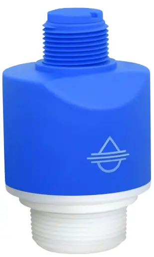
FLOWLINE LR80 Liquid and Solid Level Transmitter
WELCOME TO THE ECHO BEAM® QUICK START GUIDE
The Echo Beam® Quick Start Guide provides the basic configuration, installation and wiring instructions to get Echo Beam® up and running quickly in most level applications. If you have a question or subject that is not addressed here or wish to set up Echo Beam® with an advanced configuration such as open channel flow, please refer to the Echo Beam® Manual or visit the Flowline website at www.flowline.com.
WE DO YOUR LEVEL BEST
Thank you for purchasing Echo Beam®. We appreciate your business and look forward to reliably serving your level requirements, now and in the future.
TRANSMITTER MODELS
Offered in different models, Echo Beam® is a general-purpose 80 GHz FMCW radar level sensor that provides a continuous signal output that is proportional to the measured liquid or solids media. Before you start, please refer to the table below and make sure that the model purchased is correct for your intended application.
| Series | Max Range Liquids | Max Range Solids | Beam Angle | Material | Mounting | Application |
| LR80 | 32.81’ (10m) | 16.40’ (5m) | 8° | PVDF | 1½” NPT(G) | LIQUID
Bulk storage, day tank, skid or machine, IBC or drum, process tank, waste sump, neutralization tank, open channel, lift station, clarifier, canal, reservoir SOLIDS Small silo, bin, conveyor, transfer station, stockpile |
SIGNAL OUTPUT CONFIGURATION
Echo Beam® is offered in a single output version of 4-20mA.
- 4-20mA – When configuring Echo Beam® for 4-20mA, first connect the sensor to Level Tap™.
Once connected, configured, and installed, you can then access the sensor via Bluetooth, view the level and further adjust your configuration using Level Tap™.
RADIO COMPLIANCE
See the Radio Addendum Supplementary Instructions for radar level measuring instruments with radio approvals at www.flowline.com regarding the safe and regulatory compliant use of this device.
SAFETY AND USE
![]() The sensor is a general-purpose device and should not be used in classified hazardous environments with or near flammable or explosive media.
The sensor is a general-purpose device and should not be used in classified hazardous environments with or near flammable or explosive media.
![]() Only properly trained and plant authorized personnel wearing the appropriate personal protective equipment, following all applicable national, state or local safety regulations, codes and best practices should work on and with this sensor.
Only properly trained and plant authorized personnel wearing the appropriate personal protective equipment, following all applicable national, state or local safety regulations, codes and best practices should work on and with this sensor.
![]() The sensor’s operational reliability can only be ensured when properly used in accordance with its specifications, instructions and intended applications.
The sensor’s operational reliability can only be ensured when properly used in accordance with its specifications, instructions and intended applications.
![]() Inappropriate or incorrect use of the sensor can cause vessels to overflow and damage property, persons, or the environment.
Inappropriate or incorrect use of the sensor can cause vessels to overflow and damage property, persons, or the environment.
![]() Always install and use an independent high- and low-level safety switch control system, which in the event of sensor power loss or failure, will prevent the vessel from overflowing or emptying.
Always install and use an independent high- and low-level safety switch control system, which in the event of sensor power loss or failure, will prevent the vessel from overflowing or emptying.
![]() The operator is responsible for the safe and trouble-free selection, installation, configuration, use, removal and disposal of the sensor.
The operator is responsible for the safe and trouble-free selection, installation, configuration, use, removal and disposal of the sensor.
USING THE LEVEL TAP™ BLUETOOTH APP
Echo Beam® is configured through the Level Tap™ App, an application-based software program that uses Bluetooth to communicate with Echo Beam® via your smartphone or tablet. Level Tap™ is downloaded via the App Store for iOS and iPadOS operating systems, and Google Play for the Android operating system.
 |
 |
STARTING THE LEVEL TAP™ BLUETOOTH APP
When first starting the Level Tap™ App, you will need to CREATE AN ACCOUNT. Please enter the required information and press CREATE ACCOUNT. Once you have created an account, thereafter you will access Level Tap™ by pressing LOG IN from the Home Screen.

CONNECTING ECHO BEAM® TO LEVEL TAP™
When accessing Level Tap™, you will initially see a list of sensors that are connected or paired, as well as any unpaired sensors. Prior to your first sensor configuration, the screen will only show powered sensors that are unpaired. If there are no sensors powered on, the screen will not show any sensors. After installing Level Tap™, the next step is to power on the sensor you want to pair with the App. Wait until the sensor appears under Unpaired Sensors, then tap on the sensor shown. Finally enter the Sensor PIN code located on the sensor label to pair the sensor with the App. The sensor will then appear under Paired Sensors.
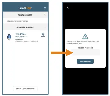
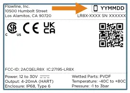
Note: The Sensor PIN Code is the manufacturer’s date code located on the label of Echo Beam® (see below).
BASIC CONFIGURATION OVERVIEW
Below are the six basic steps to configure the transmitter for operation. Each step is described in detail on the following pages.
- Measure the Tank
Measure the significant tank and fitting dimensions. - Install the Transmitter
Review the installation requirements to locate and install the sensor on the tank. - Wire the Transmitter
Follow the wiring information based on your sensor model and the signal output type. - Adjust the Dimensions
Based on the sensor’s final installed position, adjust the dimensions if necessary. - Level Tap™ Step-by-Step Configuration
Screen 1- Sensor Name – Input a unique name or identifier for each sensor or application.
- Application – Select whether the sensor is measuring liquid or solids media.
- Units of Measurement – Select the units of measurement applied in this configuration.
- Fail-Safe Output – Select the signal output if the sensor cannot measure a valid level.
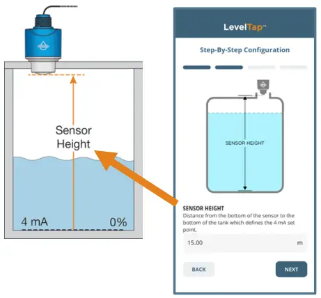
Screen 2 - Sensor Height (4mA) – Set the bottom of the measurement span or the tank empty setting.
Screen 3 - Fill-Height (20mA) – Set the top of the measurement span or the tank full set setting.
Screen 4 - Display Value – Set the sensor and App to indicate height, distance, current or percent.
If after properly installing, configuring, and testing the sensor, you find that it is not functioning as expected, use the below diagnostic step.
- Check the Echo Curve
- This tool allows you to view the echo signal returns and filter any that may be problematic.
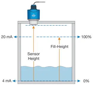
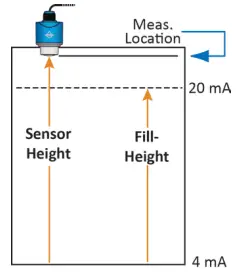
MEASURE THE TANK
STEP 1
Properly locating the sensor and correctly measuring the tank sets the foundation for sensor configuration. In doing so, consider the sensor’s mounting location with respect to relevant fittings, risers, dome tops or cone bottoms, and identify where the measurements are taken from the sensor. The required measurements for basic sensor configuration, including Sensor Height and Fill-Height, are reflected in this diagram.
MEASURING CONE BOTTOM TANKS
When installing Echo Beam® on a tank with a cone shaped bottom, the sensor’s mounting location and tank geometry may influence the sensor’s configuration setting. If your requirement is to measure into the cone, location of the sensor is critical. However, if your requirement is only to measure the straight side of the tank, the location of the sensor is not critical.
Measuring the Straight Side
The sensor location is not critical because the lowest level reading is within the straight side wall of the tank.

Measuring into the Cone
The sensor can read into the cone, but only to where most of the energy reflects to the sensor versus away from it.

Measuring to the Bottom
The sensor location is critical. The sensor must be installed over the lowest part of the tank to measure into the cone and to the bottom.

TOP OF TANK CONSIDERATIONS
When installing Echo Beam® on an enclosed tank top, the installed position of the sensor’s antenna or measurement location, above or below the top, must be taken into consideration when determining your sensor configuration settings.
Tank Top Installation
Short Riser Installation

Tall Riser Installation

SENSOR OUTPUT TO LOCAL DISPLAY/CONTROLLER
The 4-20mA output is the most common signal that can connect to a local display/controller or to remote devices such as PLCs, SCADA, DCS. The 4-20 mA signal is set relative to the Sensor Height and Fill-Height settings. These settings create an operational range that can be translated into a level reading in defined units (i.e., inches, feet, gallons, meters, liters, etc.).
In the example to the right, the Sensor Height sets the 4mA to the bottom of the tank. Fill-Height sets the 20mA to a level close to the top of the tank. The 4-20mA sensor range correlates to actual units of level measurement. The operational range now will have engineering values of 0 to 10 feet, or 0 to 1000 gallons, or 0 to 120 inches.

Note: If your tank has markers or ticks indicating a specific volume along one side of the tank, set your Fill-Height to one of these ticks / markers for easy conversion to known volume.
INSTALL THE TRANSMITTER
STEP 2
Echo Beam® measures the air gap distance between the bottom edge of the sensor’s antenna and the liquid or solid media surface. To properly install the sensor, adhere to the following installation best practices:
- Locate the sensor where there are no obstructions between the bottom edge of the sensor’s installed antenna and the bottom of the empty tank, including its measurement beam angle. Obstructions such as ladders, tank walls or seams, liquid or solids inflow streams, piping, mixer blades, other sensors, heating coils, submersible pumps, struts or apparatus, can disrupt the sensors measurement signal.
Structures or Apparatus
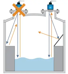
Pipes or Inflow Streams

Mixers, Pumps or Heaters
Note: Echo Beam® transmits a conical shaped RF measurement signal that spreads over a distance based on its beam angle. The below charts indicate the beam diameter or minimum free space required for each model at various measurement heights. If the sensor cannot be located away from obstacles that partially intrude into the beam diameter, perform a False Echo Curve configuration as described in Step 6.Beam Angle 8° Height Dia 5’ .70’ 10’ 1.40’ 15’ 2.10’ 20’ 2.80’ 25’ 3.50’ 30’ 4.20’ 
Beam Angle 8° Height Dia. 2.5m 0.35m 5.0m 0.70m 7.5m 1.05m 10.0m 1.40m - While adhering to the applicable radio license requirements, in liquid and short-range solids applications, install the sensor with the antenna perpendicular to the media surface. In longer range solids applications, point the sensor to the lowest location in the silo, which is generally in the center.
- Make sure that all parts of the sensor that will be exposed to the liquid or solids level media, and in particular, any portion inserted into the tank, are compatible with the media, the temperature and pressure.
- Install the sensor in a location or way that it will not come into contact with filling, rising or splashing liquid or solids level media.
- Install the sensor in accordance with all applicable national, state or local safety requirements such as the United States National Electrical Code (ANSI/NFPA 70) or the Canadian Electrical Code.
- While adhering to the minimum free space requirements, based on the model, install the sensor with the following minimum distances away from the tank side walls:
LR80: > 7.9” (200mm)

- The shield wire must be connected to electrical ground.
- Avoid operation of the sensor on a vehicle moving on a public highway.
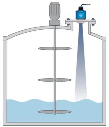
CONE BOTTOM TANKS (SOLIDS)
Echo Beam® can be used in solids applications.
The maximum range for solids with the LR80 series is 16.4 feet (5m).
To measure as much of the solids volume as possible, the antenna must be aimed at the lowest point within the tank. With any cylindrical shaped tank with a cone bottom, the sensor should be mounted half the radius (½R) from the side wall. If ½R cannot be met, it is preferred to mount the sensor closer to the side wall and away from the center of the tank.

WIRE THE TRANSMITTER
STEP 3
Supply Voltage – 4-20mA Wiring: The sensor power supply and current signal share the same two-wire shielded cable. The sensor supply voltage should never exceed 30 VDC and be greater than 12 VDC. Always provide complete electrical and physical separation between the transmitter supply circuit and the main circuit.
Note: Remember that the output voltage of the power supply can be lower under nominal load with a sensor current of 20.5 mA or 22 mA, and/or with the addition of other instruments placed within the circuit. If voltage spikes or surges are expected, adequate isolation protection must also be provided.
4-20mA Wiring: The Red Wire or Positive (+) and Black Wire or Negative (-) terminals are for connection to a 12-30 VDC power supply or to a 4-20 mA loop power source. The wire to the terminals can be extended up to 1,000 feet using 16–22-gauge wire.

Note: The sensor should be wired with shielded 2-conductor cable (16 to 22 AWG) to protect from electromagnetic interference. If using a liquid tight connector, select a cable with an outer diameter that is designed to ensure an effective seal with the connector [typically between 0.20” to 0.35” (5 to 9 mm)].
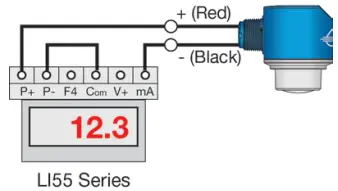
WIRING TO DISPLAYS, CONTROLLERS & PLC’S
Below are examples of how to wire Echo Beam® to common displays, controllers and PLC’s.
Data View™ LI55 Series Level Controller
Generic PLC

Generic Loop Powered Display

Data Loop™ LI23 Series Level Indicator (With Backlight)

ELECTRICAL, USAGE AND SAFETY
- Wiring should always be done by a licensed electrician in accordance with national, state and local codes.
- Never use a general-purpose transmitter (LR80 Series) in environments classified as hazardous.
- Where personal safety or significant property damage can occur due to a spill, the installation must have a redundant fail-safe backup system installed which accounts for transmitter and/or power failure.
ADJUST THE DIMENSIONS
STEP 4
Once the sensor’s installed, you may need to adjust the original Sensor Height and Fill Height dimensions based on the final mounted position of the sensor in its fitting. To assist, the below offset dimensions reflect the distance between the top of the sensor’s mounting threads or flange, to the bottom of the sensor’s antenna or point of measurement.

LEVEL TAP™ STEP-BY-STEP CONFIGURATION
STEP 5
To set up a transmitter, select one of the three setup options: Step-by-Step Configuration, Quick Adjust or Advanced. For first time configuration, we suggest using the Step-by-Step Configuration method. If you need to make any changes later, then we suggest using the Quick Adjust method.

Screen 1 – Basic Settings
- Sensor Name
- Input a unique name to identify the device (location, tank and/or media) within 12 characters.
- Application
- Select the type of media (liquid or solids) that the sensor will measure.
- Units of Measurement
- Select the desired units of measurement (inches, feet, millimeters, centimeters or meters) for the sensor.
- Fail-Safe Output
- Select the desired output if the sensor cannot measure a valid signal return or level (3.8mA, 20.5mA, 21.5mA or Hold Last Value).

- Select the desired output if the sensor cannot measure a valid signal return or level (3.8mA, 20.5mA, 21.5mA or Hold Last Value).
Screen 2 – Set the Sensor Height (4mA)
Input the distance from the bottom of the tank to the bottom of the sensor, which defines the 4mA set point.
Screen 3 – Set the Fill-Height (20mA)
Input the distance from the bottom of the tank to the maximum fill level, which defines the 20mA set point.

Screen 4 – Set the Display Value
Select the level height, air gap distance, current or percent of span value that the sensor will display.

Press WRITE TO UNIT to save these settings in the transmitter. At this point, the Echo Beam® is configured to provide a 4-20mA signal proportional to the level in your tank.
Note: The Dead Band and Maximum Range are automatically set based on the Sensor Height and Fill Height. After writing to unit, the new Sensor Height and Fill-Height, the dead band is set to 0.9 x (Sensor Height – Fill-Height) and the Maximum range is set to 1.05 x (Sensor Height).
CHECK THE ECHO CURVE
STEP 6
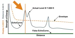
This function graphically displays the primary echo return(s) the transmitter sees, the location and amplitude of the return(s), and the numeric air gap distance from the transmitter’s measurement location to the level below.

Note: This step should only be performed after having completed the prior four configuration steps and with the transmitter installed on the tank.
- Vertical Axis (Y-axis) – Provides the strength of the signal being measured by the radar transmitter. The value is in units of decibels (dB).
- Horizontal Axis (X-axis) – Provides the distance away from the bottom of the radar transmitter. The value is in units of length (e.g., Feet, Meters, etc.)
- As you move from left to right, you are moving further away from the bottom of the transmitter.
- Blue Line – Represents the actual Echo Curve with the peak being the liquid or solid level.
- Always check to see if the peak matches the location of the level.
- Orange Line – Represents the threshold used to filter out false signals.
- This is the baseline that is used to identify a potential level reading.
- Any signal below this line will be ignored while any signal above the line is a potential level reading.
- Green Line – Represents the False Echo Curve.
- Creating a False Echo Curve will help to filter out potential false signals and will improve the performance of Echo Beam®.
Note: If there are multiple returns above the Orange Line, then it is suggested to create a False Echo Curve.
- Creating a False Echo Curve will help to filter out potential false signals and will improve the performance of Echo Beam®.
What is a Good Echo Curve?
Echo Curve presents a physical representation of the return signal across the operational range for the radar transmitter. There are two components to observe when looking at the Echo Curve:
- Check the Peak(s) along the Echo Curve
- Ideally, there should be a significant peak which represents the liquid or solids level in the tank.
- This peak should be above the Orange Line (Threshold Filter).
- There may be more, and smaller peaks located before and after the large peak.

- Check the Location of Peak (Return)
- To the left of the Echo Curve, there are two values.
- Display Value represents the air gap distance from the radar transmitter to the level.
- Distance Value represents the air gap distance from the radar transmitter to the peak amplitude location.

- These two values should be close to one another (or the same value).
- The example above indicates that the liquid level is located 7.028 feet away (Display Value) and the peak amplitude is also located 7.028 feet away (Distance Value) from the radar transmitter.
- The liquid or solids level should be at this peak location.
What is a Bad Echo Curve?
There are several elements which indicate a bad Echo Curve.
- Peak before the liquid or solids level
- If the most significant peak is ahead of/above the actual level of liquid or solids, this typically indicates interference from a physical object that is reflecting the radar energy back to the transmitter.
- Performing a False Echo Curve will allow the Echo Beam® to filter out this false signal.
- Peak after the liquid or solids level
- If the most significant peak is behind/below the actual level of liquids or solids, this typically indicates interference from a physical object that is reflecting the radar energy back to the transmitter.
- Performing a False Echo Curve will allow the Echo Beam® to filter out this false signal.
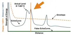
- Multiple peaks before or after the liquid or solids level
- If there are multiple peaks, the Echo Beam® may have trouble identifying which is the correct peak (liquid or solids level).
- Performing a False Echo Curve will allow the Echo Beam® to filter out the false signals.
- Also consider activating the Multiwave filter which can be found under Configuration > Advanced > Settings > Level Variables.
- Change variable from No to Yes.

- Change variable from No to Yes.
- Peak underneath the Orange Line
- If the most significant peak is beneath the Orange Line (Threshold Filter), then the return signal is weak.
- Consider changing the first Echo filter, which can be found under Configuration > Advanced > Settings > Signal Properties.

- Change variable from the default of Normal to Big, Bigger or Biggest.
- Big will increase the peak by -10dB, Bigger by -20dB and Biggest by -40dB.
- Performing a False Echo Curve will also allow the Echo Beam® to filter out this false signal, making it easier to identify the actual liquid or solids level.
- Peak significantly above the Orange Line
- If the most significant peak is way above the Orange Line (Threshold Filter), then the return signal is strong and could affect the accuracy when the level is close to full.
- Consider changing the first Echo filter, which can be found under Configuration > Advanced > Settings > Signal Properties.
- Change variable from the default of Normal to Small which will decrease the peak by -10dB.

- Change variable from the default of Normal to Small which will decrease the peak by -10dB.
DIAGNOSTICS
- False Echo Curve
- Obstructions in the tank (mixer blades, side wall weld joints, material build-up, submersible pumps, piping or other apparatus), tall tank risers or installation fittings can create false signal returns that impair the transmitter’s measurement.
- This function maps all echo returns within the tank, differentiating between good and false echoes.
- It stores those identified as false into the False Echo Curve.
- These returns will not be considered in the level measurement.
- This setting does require a manual entry of the distance from the bottom of the transmitter to the surface of the liquid or solids.
- Multiply the Current Distance by 0.95 and Enter that value into False Echo Curve and click on Save to begin the auto mapping.
Note: A False Echo Curve should be performed when the tank is empty or as close to empty as possible. This is so all false reflections will be detected.
- Multiply the Current Distance by 0.95 and Enter that value into False Echo Curve and click on Save to begin the auto mapping.
- A simple trick is to switch the Display setting to Distance, then observe the Distance value on the
Transmitter’s information page.

- The Distance value shows the exact distance from the media surface to the bottom of the transmitter.
- Be sure to return Display Setting to Level Height if that was your pervious setting.

Note: To remove or undo the False Echo Curve, enter the value 0.001 and click on Create. This will erase the False Echo Curve.
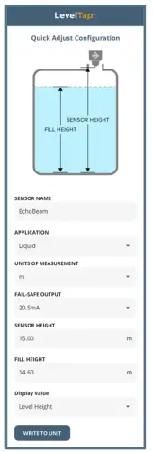
QUICK ADJUST
Quick Adjust is ideal for making changes to the main level settings. It can also as a quick configuration method for experienced users of the Level Tap™ App. To access Quick Adjust, open Configuration and then select Quick Adjust.
- Sensor Name
- Input a unique name to identify the device (location, tank and/or media) within 12 characters.
- Application
- Select the type of media (liquid or solids) that the sensor will measure.
- Units of Measurement
- Select the desired units of measurement (inches, feet, millimeters, centimeters or meters) for the sensor.
- Fail-Safe Output
- Select the desired output if the sensor cannot measure a valid signal return or level (3.8mA, 20.5mA, 21.5mA or Hold Last Value).
- Sensor Height (4mA)
- Input the distance from the bottom of the tank to the bottom of the sensor, which defines the 4mA set point.
- Fill-Height (20mA)
- Input the distance from the bottom of the tank to the maximum fill level, which defines the 20mA set point.
- Display Value
- Select the level height, air gap distance, current or percent of span value that the sensor will display
- Select the level height, air gap distance, current or percent of span value that the sensor will display
Press WRITE TO UNIT to save any changes to the sensor.
WARRANTY
Flowline warrants to the original purchaser of its products that such products will be free from defects in material and workmanship under normal use and service in accordance with instructions furnished by Flowline for a period of two years from the date of manufacture of such products. Flowline’s obligation under this warranty is solely and exclusively limited to the repair or replacement, at Flowline’s option, of the products or components, which Flowline’s examination determines to its satisfaction to be defective in material or workmanship within the warranty period. Flowline must be notified pursuant to the instructions below of any claim under this warranty within thirty (30) days of any claimed lack of conformity of the product. Any product repaired under this warranty will be warranted only for the remainder of the original warranty period. Any product provided as a replacement under this warranty will be warranted for the full two years from the date of manufacture.
RETURNS
Products cannot be returned to Flowline without Flowline’s prior authorization. To return a product that is thought to be defective, go to www.flowline.com, and submit a customer return (MRA) request form and follow the instructions therein. All warranty and non-warranty product returns to Flowline must be shipped prepaid and insured. Flowline will not be responsible for any products lost or damaged in shipment.
LIMITATIONS
This warranty does not apply to products which: 1) are beyond the warranty period or are products for which the original purchaser does not follow the warranty procedures outlined above; 2) have been subjected to electrical, mechanical or chemical damage due to improper, accidental or negligent use; 3) have been modified or altered; 4) anyone other than service personnel authorized by Flowline have attempted to repair; 5) have been involved in accidents or natural disasters; or 6) are damaged during return shipment to Flowline. Flowline reserves the right to unilaterally waive this warranty and dispose of any product returned to Flowline where: 1) there is evidence of a potentially hazardous material present with the product; or 2) the product has remained unclaimed at Flowline for more than 30 days after Flowline has dutifully requested disposition. This warranty contains the sole express warranty made by Flowline in connection with its products. ALL IMPLIED WARRANTIES, INCLUDING WITHOUT LIMITATION, THE WARRANTIES OF MERCHANTABILITY AND FITNESS FOR A PARTICULAR PURPOSE, ARE EXPRESSLY DISCLAIMED. The remedies of repair or replacement as stated above are the exclusive remedies for the breach of this warranty. IN NO EVENT SHALL FLOWLINE BE LIABLE FOR ANY INCIDENTAL OR CONSEQUENTIAL DAMAGES OF ANY KIND INCLUDING PERSONAL OR REAL PROPERTY OR FOR INJURY TO ANY PERSON. THIS WARRANTY CONSTITUTES THE FINAL, COMPLETE AND EXCLUSIVE STATEMENT OF WARRANTY TERMS AND NO PERSON IS AUTHORIZED TO MAKE ANY OTHER WARRANTIES OR REPRESENTATIONS ON BEHALF OF FLOWLINE.
This warranty will be interpreted pursuant to the laws of the State of California. If any portion of this warranty is held to be invalid or unenforceable for any reason, such finding will not invalidate any other provision of this warranty.
For complete product documentation, video training, and technical support, go to www.flowline.com.
For phone support, call 562-598-3015 from 8am to 5pm PST, Mon – Fri.
(Please make sure you have the Part and Serial number available.)
CUSTOMRT SUPPORT
©2023 Flowline, Inc.
All Rights Reserved
![]()
Flowline, Inc. | 10500 Humbolt Street, Los Alamitos, CA 90720 p 562.598.3015 f 562.431.8507 w flowline.com
![]()
![]()
Documents / Resources
 |
FLOWLINE LR80 Liquid and Solid Level Transmitter [pdf] User Guide LR80 Liquid and Solid Level Transmitter, LR80, Liquid and Solid Level Transmitter, Solid Level Transmitter, Level Transmitter, Transmitter |
